TFT-Display Datenblatt - Hy-Line
TFT-Display Datenblatt - Hy-Line
TFT-Display Datenblatt - Hy-Line

Create successful ePaper yourself
Turn your PDF publications into a flip-book with our unique Google optimized e-Paper software.
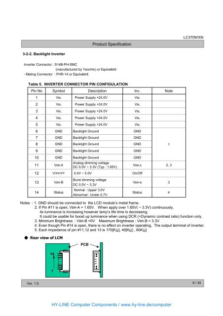
3-2-2. Backlight Inverter<br />
Ver. 1.0<br />
Product Specification<br />
Inverter Connector : S14B-PH-SMC<br />
(manufactured by YeonHo) or Equivalent<br />
- Mating Connector : PHR-14 or Equivalent<br />
Table 5. INVERTER CONNECTOR PIN CONFIGULATION<br />
Pin No<br />
1<br />
2<br />
3<br />
4<br />
5<br />
6<br />
7<br />
8 GND Backlight Ground<br />
GND<br />
1<br />
9<br />
10<br />
11<br />
12<br />
13<br />
14<br />
Symbol<br />
VBL<br />
VBL<br />
VBL<br />
VBL<br />
VBL<br />
GND<br />
GND<br />
GND<br />
GND<br />
VBR-A<br />
VON/OFF<br />
VBR-B<br />
Status<br />
Backlight Ground<br />
Analog dimming voltage<br />
DC 0.0V ~ 3.3V (Typ : 1.65V)<br />
0.0V ~ 5.0V<br />
Description<br />
Power Supply +24.0V<br />
Power Supply +24.0V<br />
Power Supply +24.0V<br />
Power Supply +24.0V<br />
Power Supply +24.0V<br />
Backlight Ground<br />
Backlight Ground<br />
Backlight Ground<br />
Burst dimming voltage<br />
DC 0.0V ~ 3.3V<br />
Normal : Upper 3.0V<br />
Abnormal : Under 0.7V<br />
Inv.<br />
VBL<br />
VBL<br />
VBL<br />
VBL<br />
VBL<br />
GND<br />
GND<br />
GND<br />
GND<br />
VBR-A<br />
On/Off<br />
VBR-B<br />
Status<br />
Note<br />
2, 3<br />
3<br />
4<br />
LC370WXN<br />
Notes : 1. GND should be connected to the LCD module’s metal frame.<br />
2. If Pin #11 is open, VBR-A = 1.65V. When apply over 1.65V( ~ 3.3V) continuously,<br />
its luminance is increasing however lamp’s life time is decreasing.<br />
It could be usable for boost up luminance when using DCR (=Dynamic contrast ratio) function only.<br />
3. Minimum Brightness : VBR-B =0V Maximum Brightness : VBR-B = 3.3V<br />
4. Even though Pin #14 is open, there is no effect on inverter operating, The output terminal of inverter.<br />
5. Each impedance of pin #11,12 and 13 is 170[KΩ], 40[KΩ] , 60KΩ]<br />
◆Rear view of LCM<br />
14<br />
1<br />
…<br />
PCB<br />
…<br />
HY-LINE Computer Components / www.hy-line.de/computer<br />
9 / 34