ED2 V1600

You also want an ePaper? Increase the reach of your titles
YUMPU automatically turns print PDFs into web optimized ePapers that Google loves.
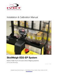
Installation & Calibration Manual<br />
SkidWeigh <strong>ED2</strong> Series<br />
Lift Truck Onboard Check Weighing Scale<br />
<strong>ED2</strong> <strong>V1600</strong><br />
Integrated Visual Data Technology Inc. 3439 Whilabout Terrace, Oakville, Ontario, Canada L6L 0A7
General Installation Guide<br />
This SkidWeigh <strong>ED2</strong> system version <strong>V1600</strong>, installation & calibration guide describes how to install, calibrate, test and<br />
use your lift truck onboard check weighing scale. Following the instructions in this guide will enable you to get your<br />
system operating quickly and with ease. In the event that you require additional assistance, please contact technical<br />
support below.<br />
Integrated Visual Data Technology Inc.<br />
3439 Whilabout Terrace<br />
Oakville, Ontario<br />
L6L 0A7<br />
Phone: 905-469-0985<br />
Email: support@sidweight.com<br />
Web: www.skidweigh.com<br />
Safety<br />
Always disconnect the vehicle battery before installing SkidWeigh systems. Make sure that the digital indicator, pressure<br />
transducer and any other associated cables are securely mounted and do not impede any of the vehicle’s controls. Use<br />
care when routing the component cables and where they will be protected. Use commonly accepted install practices for<br />
after market industrial vehicle electronic devices. The installation of SkidWeigh systems should only be performed by an<br />
acknowledged lift truck technician or other with competent knowledge of electrical and hydraulic systems.<br />
Here are two acceptable methods of making a wire connections:<br />
1.Soldering your connections (recommended)<br />
2.Crimp connectors (with the use of the proper crimping tool)<br />
Regardless of the method you choose, ensure that the connection is mechanically sound and properly insulated. Use<br />
high quality electrical tape and shrink tubing where necessary. This product is connected directly to the vehicle’s ignition<br />
switch, 12 to 55 VDC. There is no On-Off switch on the digital indicator.<br />
Electro-Magnetic Compatibility<br />
CE conformity to EC directive 89/336 (EMC) by application of harmonized standards: Interference stability EN 61000-6-2<br />
and EN 61326-1 interference emit EN 61000-6-3, EN 61326-1 for the pressure transducer.<br />
Integrated Visual Data Technology Inc. 3439 Whilabout Terrace, Oakville, Ontario, Canada L6L 0A7
SkidWeigh <strong>ED2</strong> Version 1600<br />
Our policy is one of continuous improvement and the information in this document is subject to change without notice.<br />
Check that software version displayed on the LED display is reflective of this manual.<br />
Overview of Components<br />
The standard SkidWeigh <strong>ED2</strong> check weighing system kit consist of two main components:<br />
* Digital indicator with external overload audio warning, wiring harness and anti-vibration mounting bracket.<br />
* Hydraulic pressure transducer with 3 wire connection cable.<br />
* Installation & calibration manual as well as quick reference operator usage instructions.<br />
Operational Principal<br />
The SkidWeigh <strong>ED2</strong> operational principal is based on<br />
mounting a pressure transducer into the vehicles hydraulic<br />
lifting circuit between the lift control valve and lifting cylinder(s).<br />
Upon usage proprietary software will automatically activate<br />
the “weighing cycle algorithm ” when a skid load is lifted just<br />
above the ground. The increase in pressure is converted<br />
through an electronic signal at the sample rate of 16000<br />
readings per session which is then converted into a load<br />
weight reading.<br />
Pressure<br />
Transducer<br />
T-Piece<br />
Installing the Pressure Transducer<br />
The pressure transducer must be installed in the hydraulic lift<br />
line between the lift control valve and lift cylinder(s). In<br />
some cases you can install the pressure transducer in the flow<br />
divider, drilling and tapping for 1/4”-18 NPT male in spare plug<br />
or in the body of the flow divider. Also, you can drill and tap<br />
on any “larger elbow” that might be available in the hydraulic<br />
lift circuit found in vehicles with larger hoses to accommodate<br />
larger vehicle lifting capacities.<br />
Flow Divider<br />
Integrated Visual Data Technology Inc. 3439 Whilabout Terrace, Oakville, Ontario, Canada L6L 0A7<br />
Flow Divider
Pressure Transducer Installation<br />
Precautions<br />
Before installation of the pressure transducer the hydraulic lift<br />
circuit must be pressure free. There are two ways to do that:<br />
1. Place the forks on the ground at their lowest position and<br />
make sure the hydraulic system pressure is completely free by<br />
tilting the mast forward. The chain(s) should be slack.<br />
2. Lift the forks and position them on the top of a supporting<br />
fixture. Start lowering the lift cylinder into its lowest position. Ensure that the chain(s) is slack.<br />
3 Wire Pressure<br />
Transducer Cable<br />
Make sure that that pressure transducer when installed will not<br />
touch or obstruct any assembly or moving parts during<br />
operation. The pressure transducer has a 1/4”-18 NPT male<br />
thread. Use thread seal to ensure tight fit.<br />
1/4”-18 NPT male thread<br />
Selecting the Mounting Location for<br />
the Digital Indicator<br />
Use the anti vibration mounting bracket and fasten the digital indicator on the vehicle dashboard, side rail, or over head<br />
guard, preferably on the right hand side. There are many examples of mounting locations that will depend on the vehicle<br />
model. Each SkidWeigh <strong>ED2</strong> kit comes complete with flat universal mounting brackets designed for mounting on the<br />
overhead guard.<br />
Choose the correct location and make sure that:<br />
1. The Indicator is visible and within reach of the operator.<br />
2. The location does not impede the operator safety entering the vehicle or obstruct operational sight lines<br />
Mounting Bracket<br />
Integrated Visual Data Technology Inc. 3439 Whilabout Terrace, Oakville, Ontario, Canada L6L 0A7
Electrical Connections<br />
- Orange Wire (+) Ignition switch On position (12 to 55 VDC)<br />
- Brown Wire (-) Battery negative<br />
- Red Wire, connect to RED wire of the pressure transducer cable<br />
- Black Wire, connect to BLACK wire of the pressure transducer cable<br />
- White Wire, connect to WHITE wire of the pressure transducer cable<br />
Pressure transducer cable<br />
Pressure transducer 3 wires cable must be connected to the digital indicator cable<br />
Electrical power short circuit protection<br />
- All of the SkidWeigh systems are internally short circuit protected with resettable fuse. There is no need to install<br />
external inline fuse in orange wire connected to the ignition switch.<br />
- Automotive 60 V load dump protection<br />
- Reversal power supply protection<br />
Pressure Transducer (3 wires)<br />
- Red Wire connect to the RED wire of the pressure transducer cable<br />
- Black Wire, connect to BLACK wire of the pressure transducer cable<br />
- White Wire, connect to WHITE wire of the pressure transducer cable<br />
System Power Supply<br />
(2 wires)<br />
- Orange Wire (+) Ignition switch<br />
- Brown Wire (-) Battery negative<br />
Blue, Green and Blue Wires<br />
(Application for Optional Devices)<br />
Integrated Visual Data Technology Inc. 3439 Whilabout Terrace, Oakville, Ontario, Canada L6L 0A7
‘Quick Test’ System Check<br />
Note: The following ‘Quick Test’ allows the installer to ensure that the both the electrical connections and<br />
the installation of the pressure transducer have been performed correctly. Also note the SkidWeigh system<br />
is not to be calibrated at this stage.<br />
After you have connected electrical power and the pressure transducer cable you can check system operation following<br />
these steps.<br />
1. Lower the forks to the ground.<br />
2. Turn on the ignition switch.<br />
-The digital LED display will be activated showing the software version and serial number.<br />
-The number 8 will be shown on the LED display above the Mode symbol.<br />
3. Lift the forks above the ground with a load to activate the weighing cycle.<br />
-Mode 8 will disappear and within a few seconds a load weight will show on the LED display.<br />
If the system responds as per the above test the electrical connections and pressure transducer are installed<br />
correctly. The load weight will not be accurate as the system has not been calibrated at this point.<br />
Hydraulic Accumulators<br />
The following applies to lift trucks equipped with hydraulic accumulators.<br />
Note: Before installation please ensure that the system was ordered specifically for trucks equipped with<br />
hydraulic accumulators. If not please contact technical support for confirmation and or a system with the<br />
correct software configuration.<br />
Hydraulic Pressure<br />
Transducer Mounting Location<br />
Integrated Visual Data Technology Inc. 3439 Whilabout Terrace, Oakville, Ontario, Canada L6L 0A7
Calibration Procedure<br />
The SkidWeigh <strong>ED2</strong> calibration cycle is a simple and automatic process that is completed by lifting both empty and<br />
loaded forks, and or attachment, and programming the weights into the system. The entire process takes<br />
approximately 3 minutes and will require the following to be completed in advance.<br />
1.The paper clip supplied with the system or like.<br />
2. A pre-weighed load in order to set an accurate programming standard into the system. Use an existing floor<br />
scale to verify the actual weight or a trusted accurate shipping label. For best results try to secure a load test weight<br />
that is 30 - 50% of the maximum lifting capacity.<br />
Note: The system can show the load weight in either pounds or kilograms, but not simultaneously.<br />
Therefore, calibrate in the preferred measurement unit.<br />
Two Button Calibration<br />
Mode Indicator<br />
Mode Toggle Switch<br />
Digit Toggle Switch<br />
Zeroing the Empty Forks/Attachment<br />
1. Lower the empty forks to the ground. There should be no hydraulic<br />
pressure in the hydraulic lift circuit.<br />
2. Turn the ignition switch to the on position to apply power to the system.<br />
The LED indicator will display the software version and serial<br />
number briefly before defaulting to 8 above the Mode Indicator.<br />
Integrated Visual Data Technology Inc. 3439 Whilabout Terrace, Oakville, Ontario, Canada L6L 0A7
"<br />
"<br />
"<br />
3. To begin the calibration process press the M button, using a paper clip and<br />
hold for few seconds. Eventually the 8 will change to 0 above the mode indicator.<br />
System is ready for automatic zeroing.<br />
4. With the indicator showing 0 lift he empty forks approximately 2” - 4” off the<br />
ground. With the vehicle stationary do not manipulate the tilt, side shift,<br />
or fourth lever function during the lifting process. Activate as you would<br />
normally during operation of the vehicle.<br />
5. Within a few seconds of lifting the forks, the LED display will go blank and the<br />
digit 1 will show above the Mode Indicator. On the far right side of the display a<br />
default 0 will be shown if the system is being calibrated for the first time. If a<br />
recalibration is being performed then the digit programmed from the prior session<br />
will show instead.<br />
Automatic Zeroing is Complete.<br />
Calibrating the System with a Known Load Weight<br />
6. With the LED display showing 0 at the far right it is time to enter the known weight secured prior to the calibration<br />
process. Using the paper clip enter that weight beginning with Mode 1 through 5, for weights in excess of 9999 lb./kg.<br />
If the weight is 9999 or below enter 0 for Mode 5. See the example below.<br />
(In our example we will use the known load weight of 4000)<br />
First least<br />
significant digit “0”<br />
Second least<br />
significant digit “0”<br />
Third least<br />
significant digit “0”<br />
Forth least<br />
significant digit “4”<br />
Fifth least<br />
enter “0”<br />
" "<br />
Integrated Visual Data Technology Inc. 3439 Whilabout Terrace, Oakville, Ontario, Canada L6L 0A7
7. With the system at Mode 5, after entering all digits, drive into the secured palleted<br />
load. Once the loads is secure on the lift truck make sure that all pressure is out of the<br />
hydraulic system by lowering the forks till the lift chains show slack.<br />
8. Using the paper clip press the M button to advance to Mode 6.<br />
9. Lift the known weight 2” - 4” off the ground similar to the zeroing process.<br />
With the vehicle stationary do not manipulate the tilt, side shift, or fourth lever function<br />
during the lifting process.<br />
Activate lift control lever and lift load as you would normally during operation of<br />
the vehicle.<br />
After few seconds the LED display will show calibrated load weight.<br />
System is now calibrated.<br />
Overload Warning (OPTIONAL FUNCTION)<br />
If the SkidWeigh <strong>ED2</strong> Series system utilizes the SM (Optional Overload Function) than the system will<br />
automatically default to MODE 7 when the loaded forks are lowered to the ground.<br />
Using the “M” and “Up Arrow” buttons enter the<br />
overload weight value for your application similar to<br />
the process when calibrating the system with a load<br />
weight except the MODE 7 digit remains throughout<br />
this operation. Once the last digit has been entered<br />
MODE 7 will disappear.<br />
The overload weight value is now successfully stored<br />
into the system memory.<br />
Example: Below is an example of a desired overload weight of 4850. As per the calibration process for value 9999 or<br />
less enter 0 for the 5th digit.<br />
Mode Digit 5 Digit 4 Digit 3 Digit 2 Digit 1<br />
7 0 4 8 5 0<br />
System is calibrated for both weight and overload warning<br />
Integrated Visual Data Technology Inc. 3439 Whilabout Terrace, Oakville, Ontario, Canada L6L 0A7
Operator Usage Guide<br />
<strong>ED2</strong> SkidWeigh Series<br />
Load Add Button<br />
Accumulative<br />
Load Weight<br />
Total and Print<br />
Onboard Printer<br />
<strong>ED2</strong> SkidWeigh Series<br />
• Turn on ignition switch<br />
• With LED display will show software version for the moment and mode will indicate<br />
number 8 which is the starting point to initiate load weight cycle<br />
(Loaded forks must be lowered to ground, no pressure in lift hydraulic circuit for the system to show Mode 8)<br />
Insert the forks into the pallet or product to be weighed<br />
• Lower the loaded forks to the ground.<br />
• With LED display showing number 8 in Mode, lift load just above the ground<br />
• Do not manipulate the tilt, side shifter or move vehicle during the weighing cycle<br />
• Lift the load approx. 2” off the ground using the hydraulic lift lever same as during<br />
normal usage. Do not use lift lever by lifting load “slowly”.<br />
• Within few seconds load weight will be indicated on LED display.<br />
Note: During the normal vehicle usage the LED display might show “0” or some other load<br />
weight which is due to the hydraulic “spikes”. To initiate a load weighing cycle you must lower<br />
loaded forks to the ground and LED must show number 8 in Mode window.<br />
PAGE ! 1 OF ! 2<br />
Integrated Visual Data Technology Inc. 3439 Whilabout Terrace, Oakville, Ontario, Canada L6L 0A7
Accumulative Load Weight Function<br />
• With LED display showing load weight, press “Black button” to start accumulating loads<br />
• With last load weight lifted and shown on LED display by pressing “RED button” all individual<br />
loads and total load weight will be shown.<br />
If the onboard Bluetooth printer is used than all individual load weights and total will be printed<br />
Overload Indication<br />
• The <strong>ED2</strong>SkidWeigh series with optional overload warning will automatically show on LED<br />
display the overload load value and display will “flash”. The audio / visual warning will be<br />
activated to warn the operator of such condition. To stop the overload visual / audio overload<br />
warning operator must lower the load to the ground.<br />
Two Independent Weighing Channels<br />
Two Weighing Channels Switch<br />
Channel 1 (showing Mode 8 on LED display)<br />
Channel 2 (showing Mode 82 on LED display)<br />
• Use external mounted switch to utilize the two independent weighing channels function.<br />
Example: Standard forks and long forks weighing application<br />
Note: Weighing channel one is shown as a Mode 8 and second is shown as Mode 82.<br />
Electric Pallet Truck Weighing Function (<strong>ED2</strong>-EP Skidweigh Series)<br />
• Turn on power switch (<strong>ED2</strong>-EP only). Insert forks into the load and lower it to the ground.<br />
Power On / Off Switch<br />
The LED display must show Mode 8.<br />
• Activate and hold vehicle lift control until lifting cylinder is automatically stopped<br />
• Weighing cycle will start, the LED display will go “blank” for the moment and load weight will<br />
be shown. As soon the load weight is shown the lift motor motion control is disabled<br />
• Lift cylinder motion control will go back to normal operational mode<br />
Note: During normal operation where weighing function is not required turn the indicator<br />
power switch ON /OFF to off position. (The <strong>ED2</strong>E-EP system will be turned off)<br />
INTEGRATED VISUAL DATA TECHNOLOGY INC.<br />
3439 Whilabout Terrace, Oakville, Ontario, L6L 0A7 Canada<br />
Phone: 905-469-0985 Fax: 905-825-9494 skidweigh.com<br />
PAGE ! 2 OF ! 2<br />
VER. FLS3-2<br />
Integrated Visual Data Technology Inc. 3439 Whilabout Terrace, Oakville, Ontario, Canada L6L 0A7