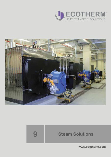
BRO Steam Solutions

You also want an ePaper? Increase the reach of your titles
YUMPU automatically turns print PDFs into web optimized ePapers that Google loves.
9<br />
<strong>Steam</strong> <strong>Solutions</strong><br />
www.ecotherm.com
Company profile<br />
ECOTHERM is the leading brand for turnkey hot water,<br />
steam and solar systems for hotels, hospitals and<br />
industry in the Middle East.<br />
ECOTHERM amazes its customers with “Individual Heat<br />
Transfer <strong>Solutions</strong>” for hot water, steam and solar generation.<br />
The following advantages mark these solutions:<br />
Individuality<br />
ECOTHERM realizes extensive turnkey systems as well<br />
as the production of separate components. Each single<br />
plant is specifically aligned to the customer’s individual<br />
requirements. The basis is an own production in Austria<br />
and a wide product portfolio.<br />
Premium quality<br />
All products made of high-class duplex stainless<br />
steel guarantee a long-life cycle and perfect hygiene.<br />
ECOTHERM is certified to ISO 9001 : 2008 with all<br />
required European standards.<br />
Innovation<br />
We are always open to the new, we constantly investigate<br />
new technologies and we develop path-breaking and future-oriented<br />
products.<br />
Premium service<br />
Clients benefit from extensive service at consulting, planning,<br />
engineering, supervision and training. ECOTHERM<br />
regularly improves the know-how of its partners and clients<br />
via selective trainings.<br />
Efficiency<br />
The ECOTHERM Group managed by the owner has slim<br />
decision-making structures. ECOTHERM turnkey solutions<br />
from one single source and the economical handling<br />
of energy resources offer an optimal cost-benefit ratio.<br />
Experience<br />
With thousands of installations the past 30 years in<br />
Europe, the Middle East, Asia, North Africa and Central<br />
America, ECOTHERM has become one of the technology<br />
and innovation leaders for individual hot water, steam and<br />
solar solutions on the market.<br />
Reliability<br />
ECOTHERM systems are monitored around the clock<br />
and can be serviced at low cost, quickly and efficiently via<br />
an advance control panel. Our designed plants have low<br />
maintenance requirements and are<br />
totally dependable.<br />
Sustainability<br />
ECOTHERM products help our customers to save energy<br />
and money. We save valuable resources through the use<br />
of renewable energies. ECOTHERM high-performance<br />
plants have minimal space requirements and provide<br />
maximum energy savings. When planning new products<br />
ECOTHERM engineers take all the qualitative and economic<br />
principles into account in accordance with ecological<br />
principles.<br />
Partnership<br />
We live in a partnership with all our customers, suppliers<br />
and employees. This relationship is characterized by<br />
honesty, commitment, openness, trust and reliability.<br />
The object is a joint long-term success.<br />
Internationality<br />
The international alignment of ECOTHERM with branches<br />
in Dubai, Kuwait, Mexico, Hungary, India and partners in<br />
more than 20 countries is the basis for our flexible and<br />
efficient project implementation that is always on schedule.<br />
2 ECOTHERM <strong>Steam</strong> <strong>Solutions</strong>
Water Sample<br />
Cooler<br />
<strong>Steam</strong> Seperator<br />
Fuel Burner<br />
Blow Down<br />
Cooler<br />
Flash<br />
Vessel<br />
<strong>Steam</strong> Flow<br />
Meter<br />
Heat<br />
Recovery<br />
Stainless Steel<br />
Chimney<br />
Plant<br />
<strong>Steam</strong> Boiler<br />
Economizer<br />
Heat<br />
Recovery<br />
<strong>Steam</strong> Header<br />
Feed<br />
Water<br />
Pumps<br />
Deaerator<br />
Feed Water<br />
Tank<br />
Pressure Reducing Station<br />
Master Control Panel<br />
Fresh Water<br />
Supply<br />
Water Softener & Chemical Dosing<br />
Condensate Recovery<br />
Reverse Osmose<br />
Clean <strong>Steam</strong><br />
Generator<br />
Legend<br />
<strong>Steam</strong> supply<br />
Condensate return<br />
Blow down<br />
Cold water<br />
Hot water<br />
Waste water<br />
Vent<br />
Contents<br />
ECOTHERM <strong>Steam</strong> <strong>Solutions</strong><br />
Your optimal solution Pages 6 - 7<br />
Products:<br />
• <strong>Steam</strong> Boilers<br />
• Economizers<br />
• Chimneys<br />
• Burners<br />
• Feed Water Tanks<br />
• Blown Down Coolers & Flash Vessels<br />
• Water Treatment<br />
• Control Panels<br />
• Condensate Return Station<br />
• Pressure Reducing Stations<br />
• Automatic Blown Down Systems<br />
• Automatic TDS Control Units<br />
• Level Control for <strong>Steam</strong> Boilers<br />
• Valves, instruments & steam ancillaries<br />
• <strong>Steam</strong> Flow Metering<br />
• Feed Water Pumps<br />
• <strong>Steam</strong> Headers<br />
• <strong>Steam</strong> Separators<br />
• Sample Coolers<br />
Pages 7 - 8<br />
Page 9<br />
Page 10<br />
Page 11<br />
Pages 12 - 13<br />
Page 14<br />
Pages 15-16<br />
Page 17<br />
Page 18<br />
Page 18<br />
Page 19<br />
Page 19<br />
Page 19<br />
Page 20<br />
Page 20<br />
Page 20<br />
Page 21<br />
Page 21<br />
Page 21<br />
Turnkey <strong>Solutions</strong>:<br />
• (Pre-)Wiring<br />
• (Pre-)Piping<br />
• Pipe Supports<br />
• Vapour Heat Exchangers<br />
• ECOTHERM High Capacity Water Heaters<br />
• High Capacity Clean <strong>Steam</strong> Generators<br />
• Smart <strong>Steam</strong> Generators<br />
Page 23<br />
Page 23<br />
Page 23<br />
Page 24<br />
Page 24<br />
Pages 25 - 26<br />
Pages 27 - 28<br />
Advantages<br />
Pages 29 - 33<br />
Technical Specifications<br />
Pages 34 - 54<br />
ECOTHERM <strong>Steam</strong> <strong>Solutions</strong><br />
3
Your optimal solution<br />
Your optimal ECOTHERM steam solution<br />
For steam systems much more components<br />
are required than for hot water<br />
systems. The spectrum ranges<br />
from oil or gas burners over feed<br />
water tanks, water treatment, clean<br />
steam generators, condensate recovery<br />
systems, steam separators up to<br />
the control panel with a touch panel.<br />
There fore ECOTHERM already plans<br />
80 to 90 percent of all details for a system<br />
in the design stage. This ensures<br />
that the suggested time schedule really<br />
works, that the costs for the project<br />
suit the suggested budget and that the<br />
desired performance can be achieved<br />
by the system. ECOTHERM steam<br />
systems are mainly installed in hotels<br />
(e. g. for the laundry), in hospitals<br />
(especially clean steam generators<br />
for e. g. cleaning the surgical instruments)<br />
or in industry.<br />
Chimneys<br />
High quality stainless steel chimneys<br />
for industrial applications and<br />
individual residental buildings.<br />
Details on page 10.<br />
Flash<br />
Vessel<br />
<strong>Steam</strong> Header<br />
Heat<br />
Recovery<br />
<strong>Steam</strong> Boilers<br />
Blow Down<br />
Cooler<br />
High efficiency, fully packaged for<br />
easy installation, robust long life.<br />
Details on pages 7 to 8.<br />
<strong>Steam</strong> Flow<br />
Meter<br />
Stainless Steel<br />
Chimney<br />
Water Sample<br />
Cooler<br />
Economizer<br />
Deaerator<br />
Smart <strong>Steam</strong> Generators<br />
Feed Water<br />
Tank<br />
High energy efficiency, robust and lowmaintenance<br />
and easy operation.<br />
Details on pages 27 to 28.<br />
<strong>Steam</strong> Seperator<br />
Heat<br />
Recovery<br />
Burners<br />
Fuel Burner<br />
Plant<br />
<strong>Steam</strong> Boiler<br />
Feed<br />
Water<br />
Pumps<br />
Gas, oil or dual fuel burners with highefficiency<br />
and approved quality.<br />
Details on page 11.<br />
Economizers<br />
Feed Water Tanks<br />
Significantly increases the boiler<br />
efficiency up to 97 percent.<br />
Details on page 9.<br />
High quality workmanship to highest<br />
European standards.<br />
Details on pages 12 to 13.<br />
4 ECOTHERM <strong>Steam</strong> <strong>Solutions</strong>
Your optimal solution<br />
Control Panels<br />
Touchscreen, 3D visualization, remote<br />
access.<br />
Details on page 17.<br />
Condensate<br />
Return Stations<br />
Fully packaged unit, ready for start-up<br />
Details on page 18.<br />
Turnkey <strong>Solutions</strong><br />
ECOTHERM offers complete turnkey<br />
steam solutions with a huge range of<br />
additional components as e. g.<br />
• (Pre-)Piping<br />
• Pipe supports<br />
• (Pre-)Wiring<br />
• Vapour heat exchangers<br />
• ECOTHERM high capacity water<br />
heaters<br />
• High capacity clean steam<br />
generators<br />
• Smart <strong>Steam</strong> Generators<br />
Pressure Reducing Station<br />
Clean <strong>Steam</strong><br />
Generator<br />
Details on pages 22 to 28.<br />
This schematic drawing<br />
shows the components of<br />
a typical ECOTHERM<br />
steam system.<br />
Master Control Panel<br />
Legend<br />
<strong>Steam</strong> supply<br />
Condensate return<br />
Blow down<br />
Cold water<br />
Hot water<br />
Waste water<br />
Vent<br />
Condensate Recovery<br />
Fresh Water<br />
Supply<br />
Water Softener & Chemical Dosing<br />
Clean <strong>Steam</strong> Generators<br />
Entirely made of high quality stainless<br />
steel. Compact, skid mounted unit.<br />
Details on pages 25 to 26.<br />
Reverse Osmose<br />
Blown Down Coolers<br />
Guarantee a safe waste water<br />
management. Details on page 14.<br />
Water Treatment<br />
In order to prevent the steam system<br />
against corrosion and scale foundation,<br />
certain components for the water treatment<br />
are added to the system as e. g.:<br />
• Water softener<br />
• Chemical dosing<br />
• Water filter<br />
• Hardness control<br />
• Reverse osmose systems<br />
Details on pages 15 to 16.<br />
ECOTHERM <strong>Steam</strong> <strong>Solutions</strong><br />
5
Products<br />
ECOTHERM steam systems consist of high quality<br />
components. Clean steam generators are made of<br />
high quality stainless steel. This high capacity products<br />
are manufactured at the ECOTHERM headquarters<br />
in Austria. The quality management system<br />
of ECOTHERM is certified according to ISO 9001 :<br />
2008 for sizing, design, production and distribution<br />
of solar, hot water and steam systems as well as of<br />
pressure vessels and heat exchangers.<br />
The products are manufactured in high quality<br />
stainless steel according to the highest European<br />
standards as e. g. ISO 3834-2 and therefore guarantee<br />
long life time and perfect hygiene. Our own<br />
test bench assures the highest quality and reliability.<br />
6 ECOTHERM <strong>Steam</strong> <strong>Solutions</strong>
Products: <strong>Steam</strong> boilers<br />
ESBI <strong>Steam</strong> Boilers<br />
Low Capacities<br />
350 - 5,000 kg/h<br />
Technical details on page 36<br />
High Capacities<br />
1,700 - 20,000 kg/h<br />
Technical details on page 37<br />
Efficiency & admissible<br />
maximum safety valve<br />
pressure<br />
• Efficiency of up to 91% and<br />
up to 95% with economizer<br />
can be achieved.<br />
• Standard design pressures<br />
of 10,13,16 and 20 bar(g)<br />
are available.<br />
Higher pressures can be manufactured<br />
on request.<br />
Design, quality & construction<br />
The ECOTHERM high output steam<br />
boilers are constructed from high quality<br />
steel and are distinguished by their<br />
solid, robust and flexible design. The<br />
boiler combines ease of operation and<br />
maintenance with optimal efficiency.<br />
The boiler is designed with all necessary<br />
inspection doors and is constructed<br />
for gas or oil firing. Construction and<br />
production is according to EN12593,<br />
the Pressure Equipment Directive<br />
97/23/EG and CE marked. An independent<br />
authorized institution carries<br />
out quality approval at our factory.<br />
The ISO 9001 certification and internal<br />
quality control ensures excellent<br />
performance and longevity of service.<br />
The client receives an economical,<br />
environmentally friendly compact unit,<br />
supplied ready for installation.<br />
ESBI steam boiler<br />
The ESBI is a three-pass flame tube/<br />
flue gas tube boiler with an inner fully<br />
water-cooled reversal chamber with<br />
finned tube wall. The boiler consists<br />
of a cylindrical shell, two endplates,<br />
gusset stay supports, flame tube, gas<br />
reversal chamber with water cooled<br />
finned tube wall and two tube bank<br />
gas passes with low gas side resistance.<br />
The boiler is completely electrically<br />
welded and provided with all<br />
required inspection openings. The<br />
spacious flame tube with low thermal<br />
heat release results in excellent<br />
combustion and low emissions. Large<br />
water content and steam space provides<br />
steady state operation.<br />
Thermal insulation<br />
The boiler is fully insulated with<br />
120mm mineral wool insulation. The<br />
casing is made of 1mm thick stucco<br />
aluminum plate with neatly trimmed<br />
connections and cut-outs. The<br />
flue gas collector is also thermally<br />
insulated.<br />
Control panel<br />
The control panel is equipped with the<br />
required controls and indicators for<br />
control and supervision of the boiler<br />
and burner. Control switches, indicator<br />
lights and alarm signals are provided.<br />
The control panel is supplied to<br />
match the burner to be used.<br />
ECOTHERM <strong>Steam</strong> <strong>Solutions</strong><br />
7
Products: <strong>Steam</strong> boilers<br />
ESBH <strong>Steam</strong> Boilers<br />
Low Capacities<br />
500 - 4,000 kg/h<br />
Technical details on pages 40 - 41<br />
High Capacities<br />
2,000 - 20,000 kg/h<br />
Technical details on pages 42 - 46<br />
Admissible maximum<br />
safety valve pressure<br />
• Standard pressures:<br />
10, 13 and 16 bar(g)<br />
• Savety valve pressures:<br />
11 and 14 bar(g)<br />
Higher pressures on request.<br />
The ECOTHERM high output steam<br />
boilers are made of high quality steel<br />
and are distinguished by their solid,<br />
robust and flexible construction, particularly<br />
by their operational ease, their<br />
easy maintenance and an optimal efficiency.<br />
The client receives an economical,<br />
environment friendly compact<br />
unit, ready for installation. The boilers<br />
are constructed for oil or gas firing.<br />
Boiler type ESBH<br />
The type ESBH classical 3 pass flame<br />
tube flue gas tube boiler consists of a<br />
cylindric shell, the two head plates, the<br />
flame tube including the back flue gas<br />
turning chamber with water cooled finned<br />
tube wall, the two flue gas passes<br />
and the fitting tube, placed either on<br />
the right (standard) or on the left. The<br />
boiler door is insulated and flue gas<br />
proof for burner mounting. The boiler<br />
is completely electrically welded and<br />
provided with all required inspection<br />
openings.<br />
The spacious flame tube with low<br />
thermal charges results in an excellent<br />
combustion and reduced emissions.<br />
The large water content secures<br />
an even burner running time and thus<br />
reduces the number of boiler starts.<br />
Thermal insulation<br />
The boiler is fully insulated with<br />
mineral wool insulation. The casing is<br />
made of structured aluminium plate.<br />
Fittings and out-cuts are properly rimmed.<br />
The flue gas collector is thermal<br />
insulated.<br />
High efficiency<br />
Due to the above technical facts an<br />
efficiency of up to 90%, respectively<br />
up to 95% with economizer, can be<br />
achieved with minimal space requirements.<br />
Thus continuos working costs<br />
are kept low. The sources of energy<br />
are used more efficiently and ECO-<br />
THERM spares the environment.<br />
Construction guiding,<br />
quality approval<br />
The boiler is designed with all necessary<br />
inspection doors. Construction<br />
and production is done according<br />
to the European Pressure Directive<br />
Equipment (PED) 97/23/EC, with CEconformity.<br />
The quality approval at ISO<br />
9001:2000 certification and the quality<br />
approval at our factory with our<br />
ECOTHERM quality performance<br />
department with works certificate guarantees<br />
the highest product quality.<br />
For installation and operation of the<br />
boiler the local laws and norms are to<br />
be respected.<br />
8 ECOTHERM <strong>Steam</strong> <strong>Solutions</strong>
Products: Economizers<br />
Economizers<br />
Potential of savings for an<br />
economizer for a steam boiler<br />
• Boiler efficiency without<br />
ECO: 88% - 91%<br />
• Boiler efficiency with ECO:<br />
94% - 97%<br />
A boiler economizer is a heat exchanger<br />
device that captures the “lost or waste<br />
heat” from the boiler's hot stack gas<br />
which could not be used inside the boiler<br />
furnace (due to physical reasons;<br />
i. e. boiler water temperature). The economizer<br />
typically transfers this waste<br />
heat to the boiler's feed water or return<br />
water circuit, but it can also be used to<br />
heat up domestic water or other process<br />
fluids. Capturing this normally lost<br />
heat reduces the overall fuel requirements<br />
for the boiler. Less fuel equates<br />
to money saved as well as fewer emissions<br />
- since the boiler now operates<br />
at a higher efficiency. This is possible<br />
because the boiler feed water or return<br />
water is pre-heated by the economizer.<br />
Therefore the boiler's main heating circuit<br />
does not need to provide as much<br />
heat to produce a given output quantity<br />
of steam or hot water. Again fuel savings<br />
are the result. Boiler economizer<br />
improve a boiler's efficiency by extracting<br />
heat from the gases discharged.<br />
<strong>Steam</strong> boilers<br />
For steam boilers, the economizer is<br />
a typically heat exchanger through<br />
which the feed water is pumped. The<br />
flue gases, having passed through the<br />
main boiler area will still be hot.<br />
The energy in these flue gases is<br />
used to improve the thermal efficiency<br />
of the boiler.<br />
Feed water<br />
The feed water thus arrives in the<br />
boiler at a higher temperature, than<br />
it would be the case if no economizer<br />
was fitted. Less energy is then<br />
required to raise the steam. Alternatively,<br />
if the same quantity of energy is<br />
supplied, then more steam is raised.<br />
The result is a higher efficiency. In<br />
broad terms a 10°C increase in feed<br />
water temperature will give an efficiency<br />
improvement of about 2%.<br />
Shell boilers<br />
Optimizing energy consumption<br />
The heat output recovery from smoke<br />
gas is limited. At smoke gases from oil<br />
or gas firing plants there’s a steam content<br />
of 100 to 120 g/kg; the condensing<br />
point of this water content is situated at<br />
57°C. For heating up the feed water by<br />
an economizer it’s only possible to use<br />
the sensible heat (dry heat) because<br />
the feed water has to have a minimum<br />
temperature of 90°C - so it’s not possible<br />
to condense the smoke gases and<br />
to use the condensing energy too.<br />
FEED WATER TANK<br />
CHIMNEY<br />
ECONOMIZER<br />
BY-PASS<br />
STEAM BOILER<br />
On shell boilers the economizer is<br />
either installed directly at the boiler<br />
or - also possible - installed as a separate<br />
unit. The smoke gas coming<br />
from the last boiler smoke gas pass<br />
is guided into the economizer.<br />
Note: The smoke gas temperature<br />
leaving a normal boiler is about<br />
50°C to 80°C higher (full load<br />
and clean heating surfaces) then<br />
the saturated steam temperature.<br />
The minimum allowed smoke gas<br />
temperature (behind economizer)<br />
depends - mainly - to chimney design.<br />
For steam boilers operated at 10<br />
bar(g) the temperature levels which<br />
could be used at the economizer<br />
are about 250°C down to 140°C<br />
(smoke gas out from boiler compared<br />
to smoke gas out from eco)<br />
- which results in a fuel saving of<br />
about 5% comparing to boilers without<br />
economizer. The feed water<br />
temperature will rise from 105°C to<br />
round 135°C in that case.<br />
ECOTHERM <strong>Steam</strong> <strong>Solutions</strong><br />
9
Products: Chimneys<br />
Chimneys<br />
CE-certified, double-wall, grimecombustion-resistant<br />
insulated<br />
chimney - respectively exhaust gas<br />
system - made of stainless steel by<br />
Jeremias, Germany.<br />
The chimney respectively exhaust gas<br />
plant is made of industrial, double-wall<br />
stainless steel system elements. It is<br />
used as an outer wall chimney as a<br />
standard but it is also suitable for assembling<br />
in buildings, as long as the<br />
system is floor-overlapping. But in this<br />
case the system has to be covered by<br />
a cored hole (which has to fulfill the<br />
fire protection requirements). This<br />
chimney can also be used for roof heating<br />
and for all connection piping.<br />
The exhaust gas plant is made of<br />
high-alloyed, austenitic stainless steel<br />
(AISI 316Ti). Its longitudinal seams<br />
are gas-shielded, arc welded and passivated<br />
via WIG.<br />
The production is externally controlled<br />
by an independent testing institute.<br />
The compliance of constant goods is<br />
checked by an internal control.<br />
The inner shell is made of 0.6-1.0 mm<br />
thick stainless steel (AISI 316Ti). The<br />
outer shell has got the same thickness<br />
at the stainless steel material number<br />
AISI 304. This material thickness offers<br />
perfect safeness against buckling<br />
and folding. The single elements are<br />
connected by plug-in sockets with<br />
overlying clamp fittings against scrolling<br />
and slipping.<br />
The inner shell of the system is able<br />
to extend freely as because of the<br />
construction of the single elements<br />
the inner shell cannot slip and consequently<br />
it remains centered without<br />
fixing on the outer shell.<br />
Thermal bridges between inner and<br />
outer shell are avoided because of<br />
this construction. The special mineral<br />
insulation (thickness 32mm) between<br />
inner and outer shell is high-temperature<br />
resistant and incombustible (material<br />
class A1 according to DIN 4102).<br />
Specifications<br />
• Thermal resistance class<br />
of the system: at reference<br />
temperature = 0.501 m²/K/W<br />
• Visible surface high-glossed<br />
(standard).<br />
• Possible designer surface:<br />
beamless, painted or grinded,<br />
as well as in copper<br />
• Inner diameter area of<br />
80 - 1,000 mm<br />
• Freestanding end above<br />
last wall holder: 3 m<br />
(up to DN 600)<br />
• Bigger diameters on request<br />
10 ECOTHERM <strong>Steam</strong> <strong>Solutions</strong>
Products: Burners<br />
Gas, Oil and Dual Fuel Burners<br />
Gas burners<br />
Gas burners of ECOTHERM steam<br />
systems have been especially<br />
designed for industrial capacity<br />
ranges. The burners are noteworthy<br />
for their large capacity and<br />
operational ranges and numerous<br />
other interesting details:<br />
• Compliance with the most stringent directives and emission limits<br />
• Large capacity and operational ranges<br />
• Stable fan reference line - good combustion behaviour<br />
• Quiet operation<br />
• Burner housing can be hinged open<br />
• Easy to install, set and service<br />
• Automatic air shut off on burner shutdown<br />
Oil burners<br />
Oil burners are of the fully automatic<br />
pressure atomizing type. Their design<br />
has been carefully considered down<br />
to the smallest detail and has been<br />
proved successfully over and over<br />
again. They meet all the demands for<br />
safety, reliability and low cost servicing.<br />
The oil burners are type<br />
tested and have the following<br />
features:<br />
• Larger range of application<br />
• Automatic sequence of operations<br />
• Stable fan characteristics - good combustion results<br />
• Air damper closed on burner shutdown<br />
• Quiet operation<br />
• Complete pre-wired integral switchgear<br />
• Hinged burner casing<br />
• Combustion head can be withdrawn when the burner is hinged open<br />
• The design of the burner makes installation, adjustment and servicing easy<br />
Dual fuel burners gas/oil<br />
Dual fuel burners satisfy the requirements<br />
for operational safety, easy<br />
installation, and reliability. They operate<br />
economically and environmentally<br />
friendly. The oil side of the dual<br />
fuel burners comply with DIN EN 267.<br />
The gas burners and the gas side of<br />
dual fuel burners comply with DIN-EN<br />
676 and the gas appliance guidelines<br />
(90/396/EEC) and are EG type tested.<br />
• Large capacity and range of application<br />
• Automatic sequence of operations<br />
• Combustion chamber pre-purge<br />
• Safe flame monitoring<br />
• Stable fan characteristics - good combustion results<br />
• Quiet operation<br />
• Hinged burner casing<br />
• Simple installation, adjustment and servicing<br />
• Easily converted to other types of gas<br />
• Fuel change by manual or automatic change over.<br />
• Automatic air closure on burner shutdown<br />
ECOTHERM <strong>Steam</strong> <strong>Solutions</strong><br />
11
Products: Feed Water Tanks<br />
Feed Water Tanks & Deaerators<br />
Description<br />
The feedwater deaerating plant, consisting of the feedwater<br />
tank and the deaerator, removes dissolved gases such as<br />
oxygen, carbon dioxide and other non-condensable gases<br />
from boiler feedwater and makeup water.<br />
For the operation of steam boilers with high thermal load<br />
on the heating surfaces boiler feedwater must be treated<br />
and conditioned.<br />
The boiler feedwater must be free of hardening constituents<br />
in order to prevent the formation of scale on the boiler heating<br />
surfaces. The presence of dissolved oxygen and carbon<br />
dioxide causes severe corrosion of metal boiler parts. The<br />
feedwater deaerating plant is custom designed for each<br />
application and meets essential thermo dynamic requirements<br />
to achieve optimal performance.<br />
Technical details on pages 48 - 49.<br />
Benefits:<br />
• Sizes from 200 to 20,000 liters<br />
• Pressure resistant<br />
• Material: mild steel, stainless steel<br />
AISI 304 / 316 / Duplex SS<br />
• Completely preassembled unit<br />
• All valves, pumps, instruments are<br />
custom-designed according to<br />
steam boiler system<br />
Function<br />
The make-up water and return condensate enters the<br />
deaerator that is fitted with a series of tray compartments<br />
to provide maximum spilling. Heating steam is fed into the<br />
deaerator from below. The make-up water and return condensate<br />
are deaerated and flow directly into the feedwater<br />
tank, which is flanged to the deaerator. The feedwater tank,<br />
which is heated by means of a steam injector, heats up the<br />
feedwater to 105°C.<br />
The solubility of gases in water can be described by Henry<br />
Dalton‘s law of absorption which states that gas solubility in<br />
a solution decreases as the gas partial pressure above the<br />
solution decreases. This means that the gas solubility in a<br />
solution decreases as the temperature of the solution rises<br />
and approaches saturation temperature.<br />
The make-up water and return condensate is distributed<br />
over the series of trays and comes in direct contact with<br />
the heating steam. This process reduces the solubility of<br />
oxygen and carbon dioxide and removes these gases from<br />
the feedwater. The released gases work their way to the<br />
top of the vessel where they are vented from the deaerator<br />
via the vent line.<br />
A temperature-controlled heating system for warming up a<br />
cold feedwater tank is provided.<br />
Due to the fact that the feedwater temperature is above<br />
100°C enough net positive suction head (NPSH) is required<br />
to ensure that the weight of the column of water in the line<br />
exerts enough pressure at the feed water pump suction to<br />
prevent the formation of steam bubbles and therefore the<br />
water from cavitating. Therefore a support construction is<br />
required.<br />
12 ECOTHERM <strong>Steam</strong> <strong>Solutions</strong>
Products: Feed Water Tanks<br />
PRESSURIZED FEED WATER TANK<br />
FLASH STEAM HEAT<br />
RECOVERY (OPTIONAL)<br />
MAKE-UP WATER<br />
VENT PIPE OUT<br />
OF BUILDING<br />
OVERFLOW TO DRAIN<br />
15<br />
12<br />
14<br />
2<br />
11<br />
FEED WATER TANK<br />
DISCHARGING AIR<br />
AND OXYGEN TO<br />
VENT out of building<br />
CONDENSATE RETURN<br />
1<br />
8<br />
10<br />
DEGASIFICATION<br />
PRESSURE<br />
REGULATION<br />
16<br />
8<br />
CONDENSATE RETURN<br />
9<br />
DRAIN<br />
17<br />
PRESSURE REDUCING STATION<br />
(OPTIONAL)<br />
FROM STEAM<br />
BOILER<br />
FEED WATER<br />
RETURN (OPTIONAL)<br />
13<br />
OPERATING PRESSURE<br />
0.2 - 0.3 bar (105°C)<br />
TS<br />
TI<br />
LEVEL<br />
CONTROL<br />
3<br />
TS<br />
7<br />
PRE-HEATING<br />
TEMPERATURE<br />
REGULATION<br />
4 DRAIN BOILER<br />
5 SAMPLE<br />
FEED<br />
WATER<br />
6<br />
WATER<br />
1 Feed Water Tank: preparing feed water for steam<br />
boilers, collecting condensate, adding chemicals,<br />
pre-heating of feed water.<br />
2 Pressurized Deaerator: removing oxygen and<br />
other gases, injection for fresh softened water,<br />
pressure control<br />
3 Level Control: to keep a constant water level in<br />
the tank a level control system is required. Also<br />
protection against low and high water is installed.<br />
4 Drain: for draining of the tank<br />
5 Boiler feed water: feed water supply connection to<br />
feed water pumps and boilers<br />
6 Sample water: connection to feed water sample<br />
cooler. Water quality needs to be checked daily<br />
7 Pre-heating of feed water to protect the boiler<br />
against too high temperature differences and heat<br />
tensions, feed water needs to be pre-heated by<br />
steam injection.<br />
8 Condensate return: collecting the condensate<br />
from different consumers, e. g. steam pipe draining<br />
points, heat exchangers, laundry machines.<br />
9 Pressure reducing station to provide exact<br />
needed pressure for pre-heating and degasification,<br />
steam pressure can be adjusted by pressure<br />
reducing station<br />
10 Degasification pressure regulation for removal<br />
of different gases from the feed water, a steam<br />
injection in deaerator is necessary. This injection<br />
should keep a constant tank pressure of about<br />
0.3 bar(g) for optimal degasification<br />
11 Discharging air and oxygen vent (out of<br />
building) removing port of waste gases. also<br />
a vapour heat exchanger (flash steam) can be<br />
installed on this port. (17)<br />
12 Safety valve high pressure protection valve<br />
opens when pressure increases.<br />
13 Feed water return (optional): in big boiler systems<br />
a 3-way valve control for feeding of steam boilers<br />
is proposed. In case of low load feed water will be<br />
returned to feed tank.<br />
14 Vacuum breaker: protection against negative<br />
pressure<br />
15 Overflow: protection against high water<br />
16 Manhole / handhole: will be provided for easy<br />
inspection and cleaning<br />
17 Flash <strong>Steam</strong> (Vapour): heat exchanger uses the<br />
“waste energy” to heat up make-up water before<br />
entering the deaerator<br />
ECOTHERM <strong>Steam</strong> <strong>Solutions</strong><br />
13
Products: Blow Down Coolers<br />
Blow Down Coolers & Flash Vessels<br />
<strong>Steam</strong> boilers must be blown down to remove contaminants,<br />
as a too high level will cause foaming and scaling<br />
of the boiler tubes. A build-up of solids at the bottom of the<br />
boiler could also have serious consequences. Most modern<br />
boilers are fitted with TDS controls to remove dissolved<br />
solids, and a blowdown valve that is opened at regular<br />
intervals to remove precipitated solids.<br />
Because the bottom blowdown valve is opened just a few<br />
seconds per day, it is not economical to recover the heat,<br />
yet water cannot be discharged to drain unless it is cool.<br />
Nowadays, blowdown vessels have replaced blowdown<br />
pits as the recommended way of cooling this water.<br />
Blowdown from TDS controls should ideally be connected<br />
to a heat recovery system inside a flash vessel. Where<br />
this is not practical, TDS blowdown may also be piped to a<br />
blowdown vessel.<br />
User benefits:<br />
• Three inlets as standard with dedicated bottom blowdown<br />
and TDS connection.<br />
• Fully complies with the requirements of the European<br />
Pressure Equipment Directive 97/23/EC.<br />
• Complete systems normally readily available from<br />
stock.<br />
• Quick and easy to install and maintain.<br />
For flash vessels an internal heat<br />
recovery system is provided.<br />
DISCHARGING AIR<br />
AND OXYGEN TO<br />
VENT out of building<br />
Important factors for sizing of blown<br />
down coolers & flash vessels:<br />
• Boiler pressure<br />
• Number of boilers<br />
• Duration of blow down<br />
• Blown down line size<br />
• Length of blow down line between the boiler and<br />
the blow down vessel<br />
• Blow down regime<br />
DRAIN<br />
14 ECOTHERM <strong>Steam</strong> <strong>Solutions</strong>
Products: Water Treatment<br />
Water Softener<br />
Water filter<br />
Application<br />
Automatic volume-controlled softener producing soft water<br />
by means of ion-exchange. Particularly suitable in case<br />
of unsteady soft water consumption. Not recommended in<br />
case of fluctuating raw water hardness.<br />
Design<br />
• Ion-exchange tank made of glass-fibre reinforced<br />
plastic with PE<br />
• Inliner, filled with ion exchange resin on a layer of<br />
supporting gravel,<br />
• Brine tank with salt tray, supporting body, standpipe<br />
and brine valve and plastic cover,<br />
• Hose connecting the central distribution valve<br />
• Adapter with second ion-exchange vessel,<br />
• Central distribution valve made of red brass alloy, the<br />
controller and turbine water meter mounted on its top<br />
Chemical Dosing<br />
Technical details on page 50.<br />
Controller<br />
• Electrical connection 230 V ± 10 %, 50 - 60 Hz<br />
• Electricity supply for electronics and motored drive<br />
via adapter 230 V / 12 V (AC)<br />
• Energy consumption max. 10 VAC<br />
• Parameter storage in case of power failure:<br />
infinitely long<br />
• Programming the regeneration initiation:<br />
- amount (in litre or m³)<br />
- interval (in days) beginning with the end of the last<br />
regeneration<br />
- initiation time (for time and volume controlled<br />
operation)<br />
Chemical Dosing<br />
Water filter<br />
Hardness Control<br />
The chemical dosing is used to<br />
control the dosage of oxygen<br />
binder, prosphat and sulfite in<br />
the feed water of steam generators.<br />
The system basically consists<br />
of a solenoid diaphragm pump,<br />
mounted on a dosing tank for<br />
storage of the chemical dosage.<br />
The plant is individually designed<br />
according to the defined boiler<br />
parameters and is delivered fully<br />
pre-assembled.<br />
The water filter is used for the<br />
coarse filtration of fresh water<br />
and is mounted prior to entering<br />
the water treatment system.<br />
The size is determined by the<br />
required amount of fresh water,<br />
the characteristics of the fresh<br />
water and the size of the water<br />
softening plant.<br />
For the ease of cleaning an integral<br />
backwashing system of the<br />
filter is used.<br />
For automatic control of the<br />
water hardness for larger systems<br />
often a self-controlled water<br />
hardness monitoring unit is<br />
used.<br />
Thus, the steam system is always<br />
perfectly protected against<br />
too hard water.<br />
Alternatively, manual water test<br />
kits can be used, which require a<br />
continuous measurement of the<br />
water quality by the operator.<br />
ECOTHERM <strong>Steam</strong> <strong>Solutions</strong><br />
15
Products: Water Treatment<br />
Reverse Osmose Systems<br />
The plant consist of:<br />
• High pressure membranes mounted on a<br />
stainless steel base frame<br />
• Checkvalve feedwater<br />
• Checkvalve cleansystem<br />
• Pressure switch as dry-run-protection<br />
• High pressure pump<br />
• Polysulfon/polyamid-membrane<br />
• Pressure gauges<br />
• Concentrate-, accumulation- and backflowvalve<br />
made of stainless-steel<br />
• Flowmeter permeate, concentrate and<br />
backflow<br />
• Control system with full automatic<br />
monitoring<br />
• Conductivity meter, digital display, operating<br />
hour meter<br />
• Adjustable limit value and alarm contact for<br />
low pressure and conductivity<br />
• Connection for niveau control, adjustable<br />
pressure- and interval flushing<br />
• Storage tanks made of stainless steel or<br />
plastic<br />
Reverse Osmosis is a process that is used to remove a<br />
wide range of salts to provide water of a high purity. Osmosis<br />
is a natural process involving fluid flow across a semipermeable<br />
membrane barrier. It is the process by which<br />
nutrients feed the cells in our bodies and how water gets to<br />
the leaves at the top of trees. Reverse Osmosis systems,<br />
in their basic form, consist of a pressure pump, housing<br />
and the membrane. Water is forced into the housing under<br />
pressure and the pure water (or permeate) is collected and<br />
passed to service.<br />
Reject water (or concentrate) is collected from another outlet<br />
and routed to drain, with a portion of the concentrated<br />
water recycled back to the inlet of the pump. This means<br />
that the portion of water sent to drain is kept to a minimum.<br />
The controller used on the RO system constantly monitors<br />
the quality of the permeate water and is also linked with<br />
safety controls on the system.<br />
RO plants must be supplied with softened, de-chlorinated<br />
or de-chlorinated anti scalent dosed water. A duplex softener<br />
is recommended for continuous operation.<br />
The size of the RO and choice of membrane will be determined<br />
by the permeate quantity required, feed water salinity<br />
and permeate quality expected. Low energy membranes<br />
allow the units to run at pressures around 10 to 13bar, and<br />
as such the pressure booster pumps required to generate<br />
the pure water are smaller, and the power consumption is<br />
reduced significantly.<br />
Additional recommended is also a storage tank which is<br />
used for reception of the pure-water.<br />
The size of this tank / these tanks should be in coordination<br />
with minimum and maximum RO water demand to ensure<br />
constant operation of the RO system.<br />
16 ECOTHERM <strong>Steam</strong> <strong>Solutions</strong>
Products: Control Panels<br />
Control Panels<br />
Description<br />
The ECOTHERM control panels are all-in-one panels.<br />
They unify control and HMI in one compact<br />
unit. In the control cabinet, space is saved and<br />
the amount of wiring is reduced. Different processor<br />
variations and display sizes open a diversity<br />
of configuration possibilities. The user therefore<br />
acquires economic automation hardware. Decentralized<br />
solutions are simple to implement through<br />
the integrated VARAN interface. The software also<br />
follows the integration concept and simplifies programming.<br />
The TFT color display with touch screen<br />
provides high operating comfort for visualization.<br />
Master Control Panel<br />
The purpose of the master control panel is to organize<br />
the equipment of the whole boiler plan room.<br />
Each component with need of electrical supply is<br />
connected to this control panel and its actual operation<br />
mode is shown on a visual 2D/3D mimic diagram.<br />
Interfaces for BMS<br />
There exist several interfaces with existing BMS<br />
(building management systems) in order to<br />
share and/or transfer process data: RS232, CAN<br />
bus, ETHERNET and a USB port at the front side<br />
of the control panel.<br />
Control panels are individually and project-specificmanufactured<br />
by ECOTHERM.<br />
Main tasks:<br />
• Timed automatic changeover of the boilers<br />
• Automatic changeover of the boilers in case of failure<br />
cut out<br />
• Automatic start of 2nd boiler in case of high demand<br />
• Automatic changeover to standby pump in case of<br />
pump failure<br />
• Timed automatic run of standby pump - to avoid<br />
pump-block<br />
• On/Off switch for all plant room components<br />
• Operation/failure indication of main components on<br />
mimic diagram<br />
• BMS connection for failure signal<br />
• Remote control<br />
• Integrated panel cooling device<br />
• Custom designed hard- and software<br />
Highlights<br />
• Scalable: the right CPU for any requirement<br />
• Integrated: application software compatibility<br />
• Compact: space-saving installation in the<br />
control cabinet<br />
• Simple: one engineering tool for any task<br />
ECOTHERM <strong>Steam</strong> <strong>Solutions</strong><br />
17
Products: Condensate Return Station & Pressure Reducing Stations<br />
Condensate Return Stations<br />
Description<br />
The condensate recovery units are designed to handle hot<br />
condensate, which is commonly returned for use as boiler<br />
feedwater. They can handle high quantities at 98°C with<br />
pump delivery heads up to 30 - 35 meters. A unit comprises<br />
three main parts - receiver, pump/pumps and control panel.<br />
Standards<br />
This product fully complies with the requirements of the<br />
European Machinery Directive 98/37/EC, European Low<br />
Voltage Directive 72 / 73 / EEC and European Electromagnetic<br />
Compatibility Devices Directive 89/336/ EEC.<br />
This product is not a pressurized vessel and therefore<br />
does not need to comply with the European Pressure<br />
Directive 97/23/EC.<br />
• Receivers are manufactured of mild steel or SS<br />
304/316. All sizes are fitted with adequately sized vent,<br />
overflow, drain and inlet connections flanged to PN16 or<br />
screwed. A water level gauge and control is provided.<br />
• Pumps are designed for operation under conditions of<br />
low NPSH to handle hot condensate with the minimum<br />
of flooded suction. They are directly coupled to motors<br />
having class F insulation (class B temperature rise) and<br />
motor enclosure rating IP54 minimum.<br />
• Control: Receivers are fitted with solid state level<br />
control’s which provides on / off cascade pump operation.<br />
The control panel incorporates electrical equipment<br />
suitable for 400 volt, 3 phase, 50 Hz, 4 wire supply.<br />
Control equipment is installed in a pre-wired IP54 rated<br />
metal enclosure. Connections for BMS interface are<br />
provided to monitor pump run or tripped condition.<br />
• Pump fitting: The motor and pumps are mounted<br />
under the receiver with over size suction inlet pipework<br />
and isolation valves. The pump discharge outlet is fitted<br />
with a non return valve and a pressure gauge.<br />
Technical details on page 51.<br />
Pressure Reducing Stations<br />
It is more efficient and economic to<br />
produce steam at high pressures<br />
ready for delivery through the distribution<br />
system. This may mean that the<br />
pressure needs to be reduced prior to<br />
the point of use or for different parts<br />
of the system. A reliable method of<br />
providing pressure reduction is to use<br />
a pilot operated pressure reducing<br />
valve station.<br />
Every pressure reducing station is<br />
custom designed according to<br />
required steam flows and pressures.<br />
18 ECOTHERM <strong>Steam</strong> <strong>Solutions</strong>
Products: Blow Down Systems, Control Units, <strong>Steam</strong> Boilers<br />
Automatic Blow Down Systems<br />
The automatic boiler blow down<br />
system allows the built up of sludge in<br />
the bottom of the boiler to be flushed<br />
regulary by a timer controller which<br />
cyclically opens a pneumatically<br />
actuated blow down valve. Blow down<br />
interval and duration are to be set<br />
by the user according to the water<br />
characteristics. The system avoids<br />
wasted heat and repetition or<br />
omission which occurs with manual<br />
blow down.<br />
Blow Down<br />
Valve<br />
Blow Down<br />
Vessel<br />
Automatic TDS Control Units<br />
Sensor Tip with<br />
Conductivity Probe<br />
The TDS automatic control system<br />
limits the level of dissolved salts and<br />
minerals contained in the boiler water<br />
to the allowed level, which avoids<br />
carry over due to excessively high TDS<br />
levels and minimizing the amount of<br />
blowdown required.<br />
The system continuously measures,<br />
just below the water surface level,<br />
the waters electrical conductivity and<br />
compares with the set point. If the<br />
measurement is higher the TDS valve<br />
is opened until the measured value<br />
drops below the set point.<br />
Blow Down<br />
Control Valve<br />
Level Control for <strong>Steam</strong> Boilers<br />
To control and to keep a constant water<br />
level in a boiler, a level control is<br />
used, which gives a signal to the controler<br />
to switch on/off the feed water<br />
pump.<br />
Essential are also level safety devices<br />
as low and high level cut off systems<br />
and gives alarms.<br />
Low level systems consisting of two<br />
independent level probes connected<br />
to two distinct level relays. They provide<br />
a visual and acoustic alarm in<br />
case the water level falls below a preset<br />
value and permanently stops the<br />
boiler, which only is able to operate<br />
again after a manual reset.<br />
At a high level system there is also<br />
an acoustic and visual alarm in case<br />
the boiler gets over flooded. Then the<br />
boiler feed water pump is stoped until<br />
the water level returns to the normal<br />
condition.<br />
Feedwater<br />
Pump<br />
Conductivity<br />
Probe<br />
ECOTHERM <strong>Steam</strong> <strong>Solutions</strong><br />
19
Products: <strong>Steam</strong> Accessories<br />
Valves, instruments & steam accessories<br />
Whether shut off valves, pressure<br />
regulation valves, steam traps,<br />
air vents, safety valves, measuring<br />
devices or gauges are required<br />
- ECOTHERM can tailor your<br />
selected equipment to your specific<br />
requirements.<br />
In coorporation with well-known and<br />
leading suppliers for steam equipment<br />
ECOTHERM can supply the parts you<br />
need for your system.<br />
<strong>Steam</strong> Flow Metering<br />
For the universal measurement of the<br />
volume/mass flow of gases, steam<br />
and liquids an individually selected<br />
flow meter can be used.<br />
Maximum fluid temperature ranges<br />
from –200°C up to +400°C, and pressure<br />
ratings up to PN250 are possible.<br />
There is also no maintenance because<br />
no moving parts are required.<br />
Trough the inbuilt flow measurement<br />
computer the software initial settings<br />
save time and costs.<br />
The high resistance to vibrations,<br />
temperature shocks and water hammer<br />
makes the flow meter very robust.<br />
Feed Water Pumps<br />
A feed water pump is considered to<br />
guarantee continuous feed water flow<br />
to the steam boilers.<br />
In case of fault of the feed water<br />
pump, a second reserve pump is<br />
supplied, installed in parallel to the<br />
operating one.<br />
For the protection of the pumps, low<br />
water control in feed water tank and<br />
strainers are installed.<br />
For easy maintenance and servicing<br />
each pump can be removed by<br />
closing the shut off valve before and<br />
after each pump.<br />
To guarantee non cavidation on the<br />
feed water pump impeller, every pump<br />
is individually designed according to<br />
the steam plant specification.<br />
20 ECOTHERM <strong>Steam</strong> <strong>Solutions</strong>
Products: <strong>Steam</strong> Headers, Separators, Sample Coolers<br />
<strong>Steam</strong> Headers<br />
ECOTHERM steam headers are<br />
individually designed according<br />
to the maximum boiler load.<br />
Any pipe connection and steam<br />
distribution can be considered in<br />
design stage. Every steam header is<br />
equiped with one or two relay points<br />
according to the size of the header. All<br />
headers are manufactured according<br />
to European pressure directive (PED).<br />
<strong>Steam</strong> Separators<br />
Sample Coolers<br />
The ECOTHERM steam separator<br />
provides the total<br />
solution for all pipelines carrying<br />
steam, air or gas where water droplets<br />
are in suspension.<br />
The purpose of steam separators is<br />
to collect small droplets of water and<br />
separate them from the steam in the<br />
pipes.<br />
The ECOTHERM baffle type separator<br />
is designed to achieve this separation<br />
by having an internal volume many<br />
times greater than the inlet pipework.<br />
The flow velocity of the steam, air<br />
or gas is significantly reduced as it<br />
enters the body. The relatively heavy<br />
water droplets impact on the internal<br />
baffles and are then directed to the<br />
separator drain connection and removed<br />
from the system using either a<br />
steam trap, or when used on air or gas<br />
distribution system, a liquid drainer.<br />
The ECOTHERM baffle type separator<br />
is a highly efficient product, operating<br />
over a wide velocity range, leading to<br />
improved system performance.<br />
Technical details on page 53.<br />
ECOTHERM sample coolers are used<br />
to take samples of water or steam from<br />
boilers at high temperature and pressure.<br />
The counter-current flow through<br />
the shell and coil condenses the steam<br />
and cools hot fluids efficiently to enable<br />
safe sampling. When hot pressurized<br />
liquids are being cooled the sample<br />
cooler prevents “flashing-off” which<br />
can be dangerous and will result in an<br />
inaccurate sample. By utilising corrosion<br />
resistant materials for the cooler,<br />
contamination is minimized, and<br />
service life maximized.<br />
Clear results<br />
The boiler and feed water has to be<br />
analyzed daily. The sample cooler<br />
helps to cool the hot boiler and feed<br />
water down to a safe temperature.<br />
Only cooled samples will give clear<br />
results.<br />
Description<br />
The hot water from boiler and feed<br />
water tank is conducted through a<br />
stainless steel cooling serpent. This<br />
serpent is girdled with cold water in a<br />
small stainless steel vessel.<br />
Technical details on page 54.<br />
ECOTHERM <strong>Steam</strong> <strong>Solutions</strong><br />
21
www.ecotherm.com<br />
Individual Turnkey <strong>Steam</strong> <strong>Solutions</strong><br />
Individual Turnkey <strong>Steam</strong> <strong>Solutions</strong><br />
<strong>Steam</strong> systems are complex and individual.<br />
On the one hand a lot of different<br />
components have to be used.<br />
All these components need to be optimally<br />
coordinated with each other<br />
to ensure functionality and perfect<br />
efficiency right from day one. On the<br />
other hand steam systems operate<br />
with high pressures. Thus a failure<br />
can really be very dangerous for the<br />
staff operating the system as well as<br />
for the complete building. Therefore<br />
ECOTHERM offers complete individual<br />
turnkey solutions. The services<br />
range from design, 3D visualization,<br />
project management, over manufacture,<br />
pre-assembly, pre-wiring<br />
and testing to shipping, commissioning,<br />
supervision and maintenance.<br />
Experienced ECOTHERM engineers<br />
ensure that your system operates<br />
stable, save, reaches the desired output<br />
and they train your staff how to<br />
monitor and control the most important<br />
parameters of the system.<br />
Premium quality of the products and<br />
premium service during the whole project<br />
is the minimum you should claim<br />
for your individual steam system.<br />
Find the products and services<br />
included in an ECOTHERM turnkey<br />
system on the following pages.<br />
Hot Water, <strong>Steam</strong> and Solar Systems<br />
2 Turnkey <strong>Solutions</strong><br />
Find more information in our<br />
brochure “Turnkey <strong>Solutions</strong>”.<br />
22 ECOTHERM <strong>Steam</strong> <strong>Solutions</strong>
Products: Wiring, Piping<br />
(Pre-)Wiring<br />
Turnkey system from ECOTHERM<br />
meet highest quality demands. Therefore<br />
the system is pre-assembled<br />
and pre-wired in the headquarters in<br />
Austria. The complete system is fully<br />
tested and approved according to<br />
European standards.<br />
After shipping the pre-wired components<br />
can be installed very quickly.<br />
Small systems usually can go into<br />
operation within a couple of days.<br />
(Pre-)Piping<br />
Small systems are delivered including<br />
pre-piping as a standard. For larger<br />
turnkey systems ECOTHERM offers<br />
the option to individually manufacture<br />
all necessary pipes, to pre-assemble<br />
and test the complete system including<br />
the piping in the production facility<br />
in Austria and then to ship the piping<br />
in units which can easily be mounted<br />
at construction site. The complete<br />
piping is 3d visualized with CAD<br />
design prior to manufacture. The<br />
welding is done accordining to<br />
ISO 3834-2 : 2005 certification.<br />
Pipe Supports<br />
Pipe shoes and supports from Sikla<br />
in Austria have become the widely<br />
recognized “state-of-the-art” in plant<br />
engineering’s pipe installations. A modular<br />
kit gives all the freedom at the<br />
installation in the plant room. You will<br />
capitalize on simplified stock logistics.<br />
Through the combination of base<br />
unit (skid) with a set, only one type<br />
is stocked and the variations can instantly<br />
be generated depending on<br />
demand. All pipe supports and pipe<br />
shoes have a safety-relevant function<br />
within an operating plant.<br />
ECOTHERM <strong>Steam</strong> <strong>Solutions</strong><br />
23
High Capacity Clean <strong>Steam</strong> Generators<br />
Clean steam generators are used wherever plant steam,<br />
generated in fired steam boilers is not suitable. Due to the<br />
necessity of chemical dosing and the black material of the<br />
fired steam boilers, plant steam is not applicable for hygienic<br />
purposes. The ECOTHERM clean steam generator is<br />
entirely made of stainless steel to suit hygienic purposes<br />
like sterilizer units in hospitals or cleaning the stainless<br />
steel pipes of beverage & food industries. It is a compact,<br />
skid mounted unit ready for easy installation at site.<br />
Standard equipment<br />
• Clean <strong>Steam</strong> vessel made of AISI 316 Ti or duplex<br />
stainless steel<br />
• Pressure / temperature controlled<br />
• <strong>Steam</strong> trap set with ball float valve<br />
• Centrifugal feed water pump<br />
• Fully automatically control panel<br />
• Blow down vessel, stainless steel<br />
• Sample cooler, stainless steel<br />
• Safety and control utilities<br />
• Design and manufacturing according to PED 97/23/EC<br />
Capacities from 250 - 4,000 kg/h as a<br />
standard. Higher capacities on request.<br />
<strong>Steam</strong> generation:<br />
• by heat exchanger (plant steam / clean steam)<br />
• by electric heating bundle<br />
Optional equipment<br />
• with <strong>Steam</strong> Flow meter<br />
• with PRV-unit<br />
• with steam header<br />
Applications:<br />
• Sterilizers for healthcare<br />
• Sterilize in place (SIP) for<br />
food and beverages<br />
• Direct injection into the product for<br />
pharmaceuticals<br />
• Clean room humidification for<br />
biotechnology<br />
• Operating environments for<br />
electronics<br />
• Laboratories for brewing<br />
• Humidifiers<br />
Description:<br />
The clean steam is generated by plant steam or by electrical<br />
energy. The clean steam generator is loaded with softened<br />
and heated water (without lime, PH-neutral conductivity,<br />
0–30 μS). This water will become clean steam. The level<br />
control guarantees an optimized level of water and causes<br />
an alarm if the water level falls below the alarm switch.<br />
The pressure of the clean steam is controlled according to<br />
the requirement by regulation valve.<br />
A conductivity measuring unit regulates the level of minerals<br />
in the water to protect the vessel.<br />
To avoid any dirt inside the clean steam generator and to<br />
guarantee a high quality of water and a long life of the vessel<br />
is installed a blow down valve which is controlled automatically.<br />
The blow down cooler cools the hot water of the blow down<br />
to 40°C to drain the water and to avoid burnings.<br />
The clean steam generators can be manufactured completely<br />
pre-piped and wired, mounted on a stainless steel<br />
support frame.<br />
Technical details on page 52.<br />
24 ECOTHERM <strong>Steam</strong> <strong>Solutions</strong>
Products: Clean <strong>Steam</strong> Generators<br />
PLANT STEAM<br />
RO WATER<br />
SUPPLY<br />
7<br />
OVERFLOW TO DRAIN<br />
FEED WATER TANK<br />
DISCHARGING AIR AND<br />
OXYGEN TO VENT out of<br />
building<br />
6<br />
9<br />
CONDENSATE RETURN<br />
14<br />
PRE-HEATING<br />
TEMPERATURE<br />
REGULATION<br />
8<br />
VENT PIPE OUT<br />
OF BUILDING<br />
5<br />
STEAM<br />
SUPPLY<br />
4<br />
PRESSURE CONTROL<br />
PT P PL<br />
LS<br />
SOFTENED WATER<br />
SUPPLY<br />
OPERATING PRESSURE<br />
0 bar (95°C)<br />
DRAIN<br />
12<br />
TS<br />
TI<br />
MASTER CONTROL<br />
PANEL<br />
LEVEL<br />
CONTROL<br />
BOILER<br />
FEED<br />
WATER<br />
13<br />
10<br />
WATER<br />
SAMPLE<br />
COOLER<br />
TS<br />
11<br />
16<br />
CLEAN STEAM GENERATOR<br />
TI<br />
HIGH PRESSURE SURFACE<br />
BLOW DOWN<br />
TDS CONTROL<br />
3<br />
LEVEL CONTROL<br />
10<br />
1<br />
TI<br />
18<br />
SOFTENED WATER<br />
SUPPLY<br />
17<br />
2<br />
12<br />
TS<br />
15<br />
FEED WATER PUMP UNIT<br />
OVERFILL PROTECTION<br />
1 Clean <strong>Steam</strong> Generator: generation of clean,<br />
sterile steam by using high quality stainless steel<br />
materials. <strong>Steam</strong> generation by heat exchanger<br />
application.<br />
Consisting of stainless steel tank, removable<br />
heating bundle and all required connections for<br />
safety and control.<br />
2 High pressure bottom blown down control:<br />
flushing of the boiler bottom where sludge is created<br />
by timer controlled blow down valve.<br />
3 High pressure surface blown down control<br />
(TDS control) continuously measurement of water<br />
conductivity just below the water surface level. If the<br />
value is too high, valve opens until the measured<br />
value drops below the set point.<br />
4 Pressure control: pressure will be setted<br />
mechanical (by mechanical pressure control valve)<br />
or electrical by pressure transmittor (control panel)<br />
and electrical operated valve.<br />
5 <strong>Steam</strong> supply: clean steam outlet port from clean<br />
steam generator<br />
6 Feed water tank: preparing feed water for steam<br />
boilers, collecting condensate, pre-heating of feed<br />
water.<br />
7 Overflow: protection against high water<br />
8 <strong>Steam</strong> separator unit to prevent steam regulation<br />
valves from condensate, steam will be separated by<br />
using steam separator and draining unit<br />
9 Discharging air and oxygen vent (out of<br />
building): removing port of waste gases.<br />
10 Level control: to keep a constant water level in<br />
the tank a level control system is required. Also<br />
protection against low an high water is installed.<br />
11 Pre-heating of feed water to protect the boiler<br />
against to high temperature differences and heat<br />
tensions, feed water needs to be pre-heated by<br />
steam injection.<br />
12 Drain for draining of the tank<br />
13 Boiler feed water: feed water supply connection to<br />
feed water pumps and boilers<br />
14 Condensate return collecting the condensate<br />
from different consumers, e. g. steam pipe draining<br />
points, heat exchangers, laundry mashines.<br />
15 Blown down cooler to cool down the hot water<br />
from surface and bottom blow down outlets.<br />
16 Water sample cooler for daily analysis of feed<br />
water and boiler water, hot water samples have to<br />
be cooled down by water sample cooler.<br />
17 Feed water pump unit vertical multistage<br />
centrifugal feed water pump which feeds the steam<br />
generator with feed water. Pump is designed<br />
according to maximum steam pressure and flow<br />
capacity of steam boiler.<br />
18 Master Control panel entire independent steam<br />
generation regulation and safety devices control<br />
ECOTHERM <strong>Steam</strong> <strong>Solutions</strong><br />
25
Products: Clean <strong>Steam</strong> Generators<br />
Smart <strong>Steam</strong> Generators<br />
(160 - 560 kg/h)<br />
• Oil or gas fired<br />
• Vertical evaporation system<br />
• Without coil / with centrifugal pump<br />
• Particulary low-maintenance and<br />
energy-efficent<br />
In contrast to a steam generator (with<br />
heating-coil and piston pump), the<br />
system works as follows:<br />
• Controlled by the water level<br />
measured inside of the evaporation<br />
system, the centrifugal pump refills<br />
the feed water via the economizer.<br />
• The burner is controlled by steam<br />
pressure.<br />
• A multiplepass pipe transfers the<br />
burnt-gas heat through the evaporation<br />
system and to the water inside.<br />
• Additionally, the economizer transfers<br />
residual heat from the exhaust<br />
air to the feed water stream.<br />
• The special inner structure of the<br />
evaporation system provides best<br />
dry steam results.<br />
Technical details on page 47.<br />
High energy efficiency<br />
• Up to 97% combustion efficiency<br />
• Condensing heating technology (More than 100% efficiency possible with<br />
optional use of second economizer)<br />
• Minimal loss of heat in stand-by-mode<br />
• High steam quality (little entrainment of water)<br />
• 3- to 5-pass boiler technology<br />
Robust and low-maintenance<br />
• Robust pressure vessel with up to 8mm wall thickness<br />
• Integreated maintenance-free centrifugal pump<br />
• State-of-the-art, interchangeable standard burner<br />
• Gentle heating procedure within 8 minutes<br />
• Safety-related equipment exceeding the requirements of PED 97/24/EC<br />
• Components mainly serial products of established suppliers<br />
Easy<br />
• Menu-driven, easy operation by full-text touchscreen<br />
• Simple start / stop procedure by remote control, timer or manual<br />
• Parallel management of multiple boilers possible as an option<br />
• Operating pressure up to 11 bar(g).<br />
26 ECOTHERM <strong>Steam</strong> <strong>Solutions</strong>
Products: Smart <strong>Steam</strong> Generators<br />
Multiple <strong>Steam</strong> Boiler Plants<br />
(up to 2,240 kg/h)<br />
If a steam volume in excess of 560 kg/h<br />
is required or if near 100% safety in<br />
steam supply by redundancy is required,<br />
multiple steam plants should be chosen.<br />
Multiple steam plants usually use a joint<br />
water supply and joint blow-off vessel.<br />
Only several steam boiler are set up in<br />
parallel.<br />
In multiple steam plants, the capacity<br />
is adjusted to demand by a boiler<br />
sequence switching mechanism.<br />
Your advantages<br />
• Vertical pressure vessel<br />
• No heating-coil<br />
• Especially low maintenance and high energy efficiency<br />
Electric Clean <strong>Steam</strong> Generators for low capacities<br />
• Boiler and components made of high quality stainless steel<br />
• High clean steam quality<br />
• Capacity from 20kW to 80kW<br />
• Simple operation and simple maintenance<br />
• Innovative design for large water surface leads to dry steam<br />
• Integrated separator keeps the steam dry even at low pressure<br />
• Immediate load adjustment by electric power control<br />
• Operating pressure up to 12 bar<br />
• Modulating balancing control of the heating rods minimizes<br />
heating rod strain and extends the service life of the electrical<br />
components<br />
• All components are made of high-quality stainless steel and<br />
therefore offer extremely long service lifes<br />
• Low space requirements due to compact build<br />
• Rolls for simple transport or frequent relocation<br />
Technical details on page 53.<br />
• Ideal for: food/beverage producers, lab technology, hospitals,<br />
medical/pharmaceutics industry<br />
ECOTHERM <strong>Steam</strong> <strong>Solutions</strong><br />
27
Model EDRE<br />
Products: Smart <strong>Steam</strong> Generators<br />
Vapour Heat Exchangers<br />
The ECOTHERM vapour heat exchanger is used for:<br />
• Pre-heating of boiler feed water<br />
• Condensate relief<br />
• Degasification of fresh softened water and condensate<br />
• Flash steam heat recovery<br />
For this process, thermal degasification, steam is used which deaerates the<br />
gases (N 2<br />
, O 2<br />
, CO 2<br />
) out of building. Hence there is energy lost on deaerator.<br />
This “lost energy” can be used for pre-heating of cold softened water or domestic<br />
cold water.<br />
Technical details on page 54.<br />
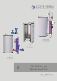
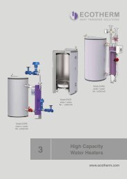
ECOTHERM High Capacity Water Heaters<br />
ECOTHERM “EDRE” high capacity<br />
water heater with storage tank.<br />
Description<br />
High capacity water heater for steam/<br />
water operation. External heat exchanger<br />
with patented free floating<br />
turbulator rods for increased efficiency<br />
and self cleaning effect. Perforated<br />
stainless steel safety cover.<br />
Fibre-fleece insulated hot water storage<br />
tank, upright standing. All parts<br />
in contact with water are made entirely<br />
of stainless steel AISI-316Ti /<br />
duplex. “Anti-Legio” design fully compliant<br />
with European anti-legionella<br />
recommendations. Microprocessor<br />
controlled modulating 2 way condensate<br />
control valve on primary circuit<br />
return line, secondary circuit circulating<br />
pump, 4 temperature sensors for<br />
pre-heat start-up, heating cycle start,<br />
heating cycle stop and anti-fouling<br />
cooling cycle. Microprocessor control<br />
unit mounted on gantry with volt<br />
free output signals for boiler request<br />
and alarm. Input signal for remote<br />
operation. All components are preassembled<br />
and wired. Simple on-site<br />
assembly.<br />
Storage tank insulation<br />
Fibre-fleece insulation with a robust<br />
PP exterior shell, patented aluminum<br />
closure strips and patented self-fixing<br />
covering rossettes, fire protection<br />
class B2 (B1 upon request).<br />
Output performance<br />
• Output rating: 100 - 2,000 kW<br />
• Storage capacity: from 300 up to 5,000 liters or larger<br />
• Peak hot water output: 1,800 - 35,900 liters / hour at 60°C<br />
(Higher output and storage capacities available on request)<br />
steam / water<br />
100 - 2,000 kW<br />
3<br />
Model EF<br />
water / water<br />
40 - 350 kW<br />
High Capacity<br />
Water Heaters<br />
Model EHRE<br />
water / water<br />
100 - 1,000 kW<br />
www.ecotherm.com<br />
Find more information in our brochure<br />
“High Capacity Water Heaters”.<br />
Special features<br />
• Stainless steel AISI-316Ti / duplex for lifelong service<br />
• Freshly made, hygienic hot water<br />
• Legionella decontamination cycle, “Anti-Legio” design<br />
• Anti-fouling cycle<br />
• Microprocessor control with optional remote control via PC<br />
28 ECOTHERM <strong>Steam</strong> <strong>Solutions</strong>
Advantages<br />
ECOTHERM steam solutions offer premium<br />
service and high quality products with several<br />
advantages:<br />
• Efficiency<br />
• Design<br />
• Individuality<br />
• Premium quality<br />
• Maximum savings<br />
• Easy control<br />
• Premium service<br />
• ECOTHERM Academy<br />
• Research & development<br />
• Know-how<br />
• Certified & approved solutions<br />
• Experience<br />
ECOTHERM <strong>Steam</strong> <strong>Solutions</strong><br />
29
Advantages<br />
Efficiency<br />
One of ECOTHERM's key values is<br />
“sustainability”. This especially drives<br />
the company to produce plants which<br />
consume as less energy as possible at<br />
reaching the desired output in means<br />
of hot water or steam. Therefore<br />
ECOTHERM has installed its own<br />
innovation management system at the<br />
headquarters in Austria.<br />
This standardarized process ensures<br />
to permanently improve existing products<br />
and components and create new<br />
products to open new possibilities to<br />
further improve the efficiency of the<br />
ECOTHERM systems.<br />
The results are innovative and technologically<br />
leading products as e. g.<br />
the ECOTHERM shell & tube heat<br />
exchanger with the patented free<br />
floating turbulator rods. With this heat<br />
Design<br />
exchanger, hot water system needs<br />
minimal floor space since hot water can<br />
be produced just on demand.<br />
Another example of ECOTHERM's innovative<br />
and efficient products are the<br />
ECOTHERM high capacity clean steam<br />
generators. Using a heat recovery unit,<br />
primary energy is saved. Moreover the<br />
clean steam generators have a compact<br />
design and are skid mounted. This saves<br />
floor space in the plant room and<br />
time for installation on site.<br />
For all individual ECOTHERM turnkey<br />
systems a detailled 3d visualization<br />
is already created in design stage.<br />
Usually 80 to 90 percent of all details<br />
are included in the design. This ensures<br />
that the final system meets the<br />
project's budget, is manufactured and<br />
delivered in time and that the desired<br />
performance of the system can be<br />
reached for sure.<br />
Moreover the CAD data from the design<br />
are the basis for the start of the<br />
operations scheduling. Due to the saved<br />
parameters e. g. also the bill of<br />
lading is created.<br />
Finally the service man uses the 3d<br />
visualization at the touch screen of<br />
the control panel in order to monitor<br />
and modify the most important process<br />
parameters.<br />
Optimal overview on the touch screen<br />
of the control panel for monitoring<br />
and controlling the system due to the<br />
3d visualization.<br />
30 ECOTHERM <strong>Steam</strong> <strong>Solutions</strong>
Advantages<br />
Individuality<br />
According to the project specifications,<br />
the ECOTHERM engineerings<br />
choose the suitable products for your<br />
individual steam solution. All components<br />
are perfectly coordinated with<br />
each other. This ensures the maximum<br />
efficiency of the system and therefore<br />
the maximum return on investment<br />
of your money.<br />
Premium Quality<br />
On the one hand ECOTHERM as a<br />
company and its products are certified<br />
and approved according to the highest<br />
European standards. But “premium<br />
quality” at ECOTHERM means much<br />
more. It is the philosophy to supply the<br />
best possible system to the customer.<br />
If we are not satisfied with a solution,<br />
we develop our own standard as e.<br />
g. the ECOTHERM touch panel for<br />
the control of the system or the ECO-<br />
THERM insulation solution, which is<br />
outstanding due to its patented components.<br />
These are just two examples<br />
where we set new<br />
standards for the<br />
market concerning<br />
quality. This philosophy<br />
is one of the<br />
main reasons why<br />
ECOTHERM is the<br />
market leader for<br />
individual turnkey<br />
solar, hot water and<br />
steam systems in<br />
the Middle East.<br />
Maximum Savings<br />
ECOTHERM systems consist mainly of<br />
high capacity components. These products<br />
achieve maximum performance<br />
with minimal space requirements. Taking<br />
into consideration that one can utilize<br />
this space for another purpose, this<br />
fact saves a lot of money.<br />
The ECOTHERM microprozessor<br />
control panel optimizes the overall<br />
performance of the system. Due to<br />
the high capacity shell & tube heat<br />
exchangers with the patented free<br />
floating turbulator rods, the burners<br />
are only started at continuous hot<br />
water demand. For small demands,<br />
the hot water in the storage tank is<br />
used. On the other hand only a very<br />
small capacity of the storage tank<br />
is heated up to 60°C. Therefore the<br />
number of burner starts per day is<br />
significantly reduced compared to<br />
conventional systems.<br />
If possible, the experienced ECO-<br />
THERM engineers further equip the<br />
system with an economizer, water<br />
treatment components and a heat<br />
recovery unit in order to further save<br />
primary energy.<br />
ECOTHERM <strong>Steam</strong> <strong>Solutions</strong><br />
31
Advantages<br />
Premium Service<br />
Supplying an individual turnkey solution,<br />
ECOTHERM provides a huge range<br />
of services ranging from design,<br />
3d visualization, project management,<br />
over manufacture, pre-assembly, prewiring<br />
and testing to shipping, commissioning,<br />
supervision and maintenance.<br />
Experienced ECOTHERM engineers<br />
ensure that your system operates<br />
stable, save, reaches the desired output<br />
and they train your staff how to<br />
monitor and control the most important<br />
parameters<br />
of the system.<br />
Premium quality<br />
of the products<br />
and premium service<br />
during the<br />
whole project is<br />
the minimum you<br />
should claim for<br />
your individual<br />
steam system.<br />
ECOTHERM Academy<br />
The aim of the ECOTHERM Academy<br />
is the strategically planned training<br />
of all employees and partners.<br />
The ECOTHERM Academy systematically<br />
identifies the needs and<br />
wishes of all participants for trainings<br />
and seminars. The strategic aims of<br />
the company for the next three years<br />
are also be considered at planning.<br />
In addition, the Academy offers optional<br />
courses from different areas.<br />
The ECOTHERM International Support<br />
Centre in Dubai plays a central<br />
role in the implementation<br />
of the<br />
trainings on an<br />
international level.<br />
The basis for the<br />
training courses is<br />
a library of so-called<br />
“ECOCELLS”.<br />
These presentations<br />
or videos<br />
cover all important<br />
issues that have<br />
to be trained.<br />
Research & Development<br />
According to its own innovation management<br />
system, ECOTHERM is permanently<br />
working on new innovative<br />
ideas. The basis for the success of this<br />
innovation management system is the<br />
production facility in Austria, which is<br />
also equipped with a testing lab.<br />
New ECOTHERM products are tested<br />
according to the highest European<br />
standards. Furthermore components<br />
from selected suppliers are also tested<br />
in detail before they may become part<br />
of an ECOTHERM turnkey solution.<br />
Together with the design<br />
department the innovative<br />
and technologically<br />
leading ECOTHERM<br />
products are optimally<br />
coordinated with other<br />
components in order to<br />
build a perfect turnkey<br />
steam system, which<br />
operates stable, safe<br />
and efficient from day<br />
one.<br />
32 ECOTHERM <strong>Steam</strong> <strong>Solutions</strong>
Advantages<br />
Know-how<br />
ECOTHERM is a family owned company<br />
with a clear vision. The goal is<br />
to become the leading brand for solar,<br />
hot water and steam systems in<br />
defined “core markets”. Furthermore<br />
there exists a clear strategy how this<br />
vision will become true. Following<br />
this strategy ECOTHERM focusses<br />
very precisely on its core<br />
business. Employees are<br />
trained in the ECOTHERM<br />
Academy, which takes into<br />
consideration the main strategic<br />
goals within the next<br />
three years. This knowhow<br />
is organized<br />
in a self-developed<br />
knowledge management system<br />
to ensure that all ECO-<br />
THERM employees have the<br />
same know-how. Additionally<br />
more than half of the employees<br />
at the ECOTHERM headquarters<br />
in Austria have already<br />
been working for the company for<br />
more than five years. All this results<br />
in experienced engineers who design<br />
your individual steam system with a<br />
high efficiency, a compact design, a<br />
maximum performance and a save<br />
and stable operation.<br />
Certified & Approved <strong>Solutions</strong><br />
The quality management system of<br />
ECOTHERM for sizing, design, production<br />
and distribution of solar, hot<br />
water and steam systems as well<br />
as of pressure vessels and heat exchangers<br />
is certified according to ISO<br />
9001 : 2008.<br />
The products are manufactured in<br />
high quality stainless steel according<br />
to the highest European standards as<br />
e. g. ISO 3834-2 and therefore guarantee<br />
long service life and perfect<br />
hygiene.<br />
Our own test<br />
bench at the ECO-<br />
THERM headquarters<br />
in Austria<br />
assures the highest<br />
quality and reliability<br />
of all products.<br />
Furthermore products<br />
from our suppliers must<br />
also be certified to the<br />
highest industrial standards<br />
in order to be approved<br />
by ECOTHERM.<br />
Experience<br />
As a result of our more than thousand<br />
in stal la tio ns in Eu ro pe, the Middle<br />
East, Asi a, North Africa and in Central<br />
America over the past twelve years,<br />
ECOTHERM has become one<br />
of the technology and innovation<br />
leaders on the market for solar, hot<br />
water and steam systems. The employees<br />
have long service records<br />
with the company and they continuously<br />
refresh their know-how through<br />
the training and seminars at the<br />
ECOTHERM Academy.<br />
ECOTHERM <strong>Steam</strong> <strong>Solutions</strong><br />
33
Technical<br />
Specifications<br />
For all products technical details are supplied in<br />
this chapter. If you need further information, ask our<br />
ECOTHERM engineers.<br />
34 ECOTHERM <strong>Steam</strong> <strong>Solutions</strong>
Technical Specifications<br />
Boiler and Feed Water Specifications<br />
for <strong>Steam</strong> Boiler Plants<br />
Feed water and raw water specifications for water softener, Reverse Osmosis and<br />
Feed water tank<br />
Feed water raw water for WS raw water for RO<br />
Working pressure bar(g) > 1 < 22 > 2.5 < 8 > 2 < 6<br />
Temperature °C - > 5 < 30°C > 5 < 40°C<br />
Properties<br />
1<br />
Noted in the past at °dH, changing factor: 1 mmol/l = 5.6 °dH (German hardness).<br />
colourless, clear, free from suspended matter and foam<br />
pH-value at 25°C > 9 > 9 > 2 < 11<br />
Sum of alkaline earth elements (Ca + Mg) 1 mmol/l < 0.02 - < 0.02<br />
°dH < 0.112 - < 0.112<br />
Conductivity at 25°C µS/cm see guidelines for boiler water specifications only < 1400<br />
Oxygen (O 2<br />
) mg/l < 0.02 - -<br />
Carbon dioxide (CO 2<br />
) dissolved mg/l < 25 - -<br />
Iron (Fe), total mg/l < 0.05 < 0.1 < 0.1<br />
Copper (Cu), total mg/l < 0.01 < 0.01 < 0.01<br />
Silicate acid (SiO 2<br />
) mg/l see guidelines for boiler water only<br />
Chloride mg/l < 0.1 < 0.1 < 0.1<br />
Consumption of Potassium permanganate mg/l < 10 < 10 < 10<br />
Oil, fat mg/l < 0.1 < 0.1 < 0.1<br />
It is not necessary to make continuous control of the following parameters: Conductivity, Oxygen (O 2<br />
), Carbon dioxide (CO 2<br />
) dissolved, Iron (Fe),<br />
total, Copper (Cu), total, Silicate (SiO 2<br />
), Consumption of Potassium permanganate, Oil, fat.<br />
Boiler water specifications for natural circulating boilers<br />
Working pressure bar(g) 1 < 22 >22 < 44<br />
Properties<br />
colourless, clear, free from suspended matter and foam<br />
pH-value at 25°C 10.5-12 10.5-12 10-11.8<br />
Sum of alkaline earth elements (Ca + Mg) 2 mmol/l < 0.02 < 0.02 < 0.01<br />
°dH < 0.112 < 0.112 < 0.056"<br />
Conductivity at 25°C µS/cm < 5000* < 5000* < 2000*<br />
Acid capacity KS 8,2 3 (p-value) mmol/l 1-12 1-12 0.5-6<br />
Carbon dioxide (CO 2<br />
) dissolved mg/l < 25 < 25 < 25<br />
Iron (Fe), total mg/l -- < 0.05 < 0.03<br />
Silicate acid (SiO 2<br />
) mg/l < 150 < 100 < 50<br />
Phosphate (P 2<br />
O 4<br />
) 4 mg/l 10-20 5-10 5-10<br />
Sodium sulphate (Na 2<br />
SO 3<br />
) 4 mg/l 5-10 5-10 3-5<br />
(Polyamide) 5 mg/l (3-5) (3-5) --<br />
1<br />
Take care to maintain the allowed value of acid capacity - at this point the allowed conductivity has to be lower on many<br />
plants; for water level electrodes minimum conductivity > 5 μS/cm<br />
2<br />
Noted in the past at °dH, changing factor: 1 mmol/l = 5.6 °dH (German hardness)<br />
3<br />
Noted in the past as p-value, changing factor: KS 8.2 = 1 according p-value = 1<br />
4<br />
Measurements only necessary if dosing chemicals are used which contains these values<br />
5<br />
It is recommended to use Amine (film producing) only instead of other dosing chemicals for boilers which have a small<br />
heating load and up to maximum 16 bar(g) working pressure. Because of the danger of foam production overdosing is not permitted!<br />
ECOTHERM <strong>Steam</strong> <strong>Solutions</strong><br />
35
THREE PASS REVERSE FLAME WET BACK BOILER<br />
.<br />
97<br />
Technical Specifications<br />
<strong>Steam</strong> boiler model ESBI-L is a reverse flame 3 pass wet back horizontal<br />
boiler . Boiler ’s body is suitable for use on gaseous and liquid fuels.<br />
The boiler is fully provided with all the accessories for regulating and safety<br />
for the automatic operation.<br />
<strong>Steam</strong> Boilers ESBI-L<br />
Model<br />
Boiler code<br />
Model<br />
Boiler code<br />
Heat output Heat input<br />
Heat output<br />
Heat input<br />
Efficiency at<br />
100% load<br />
Efficiency at<br />
100% load<br />
<strong>Steam</strong> Working P<br />
production* min/max<br />
<strong>Steam</strong><br />
production*<br />
Working P<br />
min/max<br />
Water<br />
volume<br />
Water<br />
volume<br />
Water<br />
volume total<br />
Water<br />
volume total<br />
kW kcal/h kW kcal/h % kg/h bar l l kg<br />
ESBI-L 350 86240350 238 205.100 265 227.900 90,00 90,00 350 350 8-11,5 8-11.5590 590810 810 1500 1500<br />
ESBI-L 500 86240500 341 293.000 379 325.600 90,00 500 8-11,5 670 920 1620<br />
ESBI-L 500 86240500 341 293.000 379 325.600 90,00 500 8-11.5 670 920 1620<br />
ESBI-L 650 86240650 443 380.900 492 423.200 90,00 650 8-11,5 900 1120 2000<br />
ESBI-L 650 86240650 443 380.900 492 423.200 90,00 650 8-11.5 900 1120 2000<br />
ESBI-L 800 86240800 545 468.800 606 520.900 90,00 800 8-11,5 950 1250 2120<br />
ESBI-L 800 86240800 545 468.800 606 520.900 90,00 800 8-11.5 950 1250 2120<br />
ESBI-L 1000 86241000 681 586.000 757 651.100 90,00 1000 8-11,5 1280 1830 2720<br />
ESBI-L 1000 86241000 681 586.000 757 651.100 90,00 1000 8-11.5 1280 1830 2720<br />
ESBI-L 1350 86241350 920 791.100 1022 879.000 90,00 1350 8-11,5 1475 2190 3250<br />
ESBI-L 1350 1700 86241350 86241700 1158 920 996.200 791.100 1287 1022 1.106.900 879.000 90,00 90,00 1700 1350 8-11,5 8-11.52000 1475 2640 2190 3700 3250<br />
ESBI-L 2000 86242000 1363 1.172.000 1514 1.302.200 90,00 2000 8-11,5 2300 3050 4250<br />
ESBI-L 1700 86241700 1158 996.200 1287 1.106.900 90,00 1700 8-11.5 2000 2640 3700<br />
ESBI-L 2500 86242500 1703 1.465.000 1893 1.627.800 90,00 2500 8-11,5 2490 3380 5000<br />
ESBI-L 2000 86242000 1363 1.172.000 1514 1.302.200 90,00 2000 8-11.5 2300 3050 4250<br />
ESBI-L 3000 86243000 2044 1.758.000 2271 1.953.300 90,00 3000 8-11,5 2825 4020 5650<br />
ESBI-L 2500 86242500 1703 1.465.000 1893 1.627.800 90,00 2500 8-11.5 2490 3380 5000<br />
ESBI-L 3500 86243500 2385 2.051.000 2650 2.278.900 90,00 3500 8-11,5 3600 5000 6950<br />
ESBI-L 3000 86243000 2044 1.758.000 2271 1.953.300 90,00 3000 8-11.5 2825 4020 5650<br />
ESBI-L 4000 86244000 2726 2.344.000 3028 2.604.400 90,00 4000 8-11,5 4800 6950 8550<br />
ESBI-L 3500 5000 86243500 86245000 3407 2385 2.930.000 2.051.000 3786 2650 3.255.600 2.278.900 90,00 90,00 5000 3500 8-11,5 8-11.55200 3600 7400 5000 9600 6950<br />
ESBI-L<br />
*<strong>Steam</strong><br />
4000<br />
production actual<br />
86244000<br />
from feed water at<br />
2726<br />
80°C<br />
2.344.000 3028 2.604.400 90,00 4000 8-11.5 4800 6950 8550<br />
ESBI-L 5000 86245000 3407 2.930.000 3786 3.255.600 90,00 5000 8-11.5 5200 7400 9600<br />
Weight<br />
kW kcal/h kW kcal/h % kg/h bar(g) l l kg<br />
Weight<br />
• Standard equipement:<br />
• 2 level indicators<br />
• 1 main steam stop valves<br />
• 1 pressure gauge<br />
• 1 limit pressure switch<br />
• 1 second stage pressure switch<br />
• 1 safety pressure switch, manual reset<br />
• 1 automatic level control<br />
• 1 low level safety probe<br />
• 1 extra low level safety probe<br />
• 2 feed water pumps<br />
• 2 strainers<br />
• 3 isolating valves<br />
• 3 non-return valves<br />
• 1 blowdown stop valve<br />
• 1 control panel 3/N 400V 50 bHz<br />
Model<br />
Furnace<br />
resistance<br />
Burner blast<br />
tube length<br />
Fuel consumption<br />
Dimensions<br />
H L L1 P Øc<br />
mbar mm Natural gas Diesel oil Heavy oil mm mm mm mm mm<br />
ESBI-L 350 5.0 280-330 27.1 22.3 23.5 1810 1510 1230 1840 250<br />
ESBI-L 500 6.5 280-330 38.8 31.9 33.6 1810 1510 1230 2090 250<br />
ESBI-L 650 5.0 320-370 50.4 41.5 43.6 1930 1630 1350 2130 300<br />
ESBI-L 800 5.0 320-370 62.0 51.1 53.7 1930 1630 1350 2350 300<br />
ESBI-L 1000 7.0 350-400 77.5 63.8 67.1 2140 1840 1560 2350 350<br />
ESBI-L 1350 6.5 350-400 104.6 86.2 90.6 2140 1840 1560 2760 350<br />
ESBI-L 1700 9.5 370-420 131.8 108.5 114.1 2300 1990 1710 2790 400<br />
ESBI-L 2000 10.0 370-420 155.0 127.7 134.2 2300 1990 1710 3150 400<br />
ESBI-L 2500 6.5 420-470 193.8 159.6 167.8 2460 2170 1880 3200 450<br />
ESBI-L 3000 9.0 420-470 232.5 191.5 201.4 2530 2210 1880 3700 450<br />
ESBI-L 3500 9.0 480-530 271.3 223.4 234.9 2720 2350 2020 3770 500<br />
ESBI-L 4000 10.0 480-530 310.0 255.3 268.5 2840 2470 2140 4280 550<br />
ESBI-L 5000 11.0 480-530 387.6 319.2 335.6 2960 2590 2260 4530 600<br />
36 ECOTHERM <strong>Steam</strong> <strong>Solutions</strong>
<strong>Steam</strong> Boilers ESBI-H<br />
Medium - high pressure steam boiler ESBI-H is a genuine three pass<br />
wet back horizontal fire tube boiler, designed in accordance with<br />
the latest EU codes and produced especially for industrial plants.<br />
The ESBI-H boiler is manufactured incorporating the latest technology<br />
and provides excellent performance, in order to satisfy the special<br />
requirements of reliability, endurance and control. Technical Specifications<br />
• supplied fully packaged and ready for installation<br />
• large steam space and evaporation surface for good quality dry steam<br />
• large heating surface without use of turbulators for a low heat<br />
release<br />
• flanged tube plates for full flexibility of the vessel during the<br />
combustion process<br />
• standby feed pump as standard<br />
Model<br />
Model<br />
Boiler code<br />
Boiler code<br />
<strong>Steam</strong> Working P min./max. Water volume Dry weight<br />
Heat output Heat input<br />
12 bar<br />
production 12 bar 15 bar NWL Total 12 bar 15 bar<br />
12 bar(g) 15 15 bar(g) output input production 12 bar 15 bar NWL Total 12 bar 15 bar<br />
kW kW kg/h bar bar l l kg kg<br />
ESBI-H 1000 86161000 86171000 1163 1292 1700 8 / 11.5 10 / 14.3 4565 5940 6500 7300<br />
ESBI-H 1200 86161200 86171200 1395 1550 2040 8 / 11.5 10 / 14.3 4445 5805 7100 8000<br />
ESBI-H 1500 86161500 86171500 1744 1938 2560 8 / 11.5 10 / 14.3 5475 6960 8500 9500<br />
ESBI-H 1750 86161750 86171750 2035 2261 3000 8 / 11.5 10 / 14.3 5395 6890 9600 10700<br />
ESBI-H 2000 86162000 86172000 2326 2584 3410 8 / 11.5 10 / 14.3 6615 8435 10500 11800<br />
ESBI-H 2500 86162500 86172500 2907 3230 4270 8 / 11.5 10 / 14.3 7640 9610 11500 12800<br />
ESBI-H 3000 86163000 86173000 3488 3876 5100 8 / 11.5 10 / 14.3 7955 9865 13000 14300<br />
ESBI-H 3500 86163500 86173500 4070 4522 6000 8 / 11.5 10 / 14.3 9565 11940 14300 16000<br />
ESBI-H 4000 86164000 86174000 4651 5168 6820 8 / 11.5 10 / 14.3 10280 12630 16000 18000<br />
ESBI-H 5000 86165000 86175000 5814 6460 8500 8 / 11.5 10 / 14.3 11180 14120 18000 20000<br />
ESBI-H 6000 86166000 86176000 6977 7752 10240 8 / 11.5 10 / 14.3 13345 16530 21000 23200<br />
ESBI-H 7000 86167000 86177000 8140 9044 12000 8 / 11.5 10 / 14.3 15970 20030 24000 26200<br />
ESBI-H 8000 86168000 86178000 9302 10336 13600 8 / 11.5 10 / 14.3 20050 25700 26500 29000<br />
ESBI-H 9000 86169000 86179000 10465 11628 15300 8 / 11.5 10 / 14,3 22060 28140 30000 32500<br />
ESBI-H 10000 86169900 86179900 11628 12920 17000 8 / 11.5 10 / 14.3 24620 31120<br />
Higher pressure available upon request<br />
33000 36000<br />
ESBI-H 12000 86169912 86179912 13953 15500 20000 8 / 11.5 10 / 14.3 29250 37500 38000 42000<br />
ESBI-H 1000 86161000 86171000 1163 1292 1700 8 / 11,5 10 / 14,3 4565 5940 6500 7300<br />
ESBI-H 1200 86161200 86171200 1395 1550 2040 8 / 11,5 10 / 14,3 4445 5805 7100 8000<br />
ESBI-H 1500 86161500 86171500 1744 1938 2560 8 / 11,5 10 / 14,3 5475 6960 8500 9500<br />
ESBI-H 1750 86161750 86171750 2035 2261 3000 8 / 11,5 10 / 14,3 5395 6890 9600 10700<br />
ESBI-H 2000 86162000 86172000 2326 2584 3410 8 / 11,5 10 / 14,3 6615 8435 10500 11800<br />
ESBI-H 2500 86162500 86172500 2907 3230 4270 8 / 11,5 10 / 14,3 7640 9610 11500 12800<br />
ESBI-H 3000 86163000 86173000 3488 3876 5100 8 / 11,5 10 / 14,3 7955 9865 13000 14300<br />
ESBI-H 3500 86163500 86173500 4070 4522 6000 8 / 11,5 10 / 14,3 9565 11940 14300 16000<br />
ESBI-H 4000 86164000 86174000 4651 5168 6820 8 / 11,5 10 / 14,3 10280 12630 16000 18000<br />
ESBI-H 5000 86165000 86175000 5814 6460 8500 8 / 11,5 10 / 14,3 11180 14120 18000 20000<br />
ESBI-H 6000 86166000 86176000 6977 7752 10240 8 / 11,5 10 / 14,3 13345 16530 21000 23200<br />
ESBI-H 7000 86167000 86177000 8140 9044 12000 8 / 11,5 10 / 14,3 15970 20030 24000 26200<br />
ESBI-H 8000 86168000 86178000 9302 10336 13600 8 / 11,5 10 / 14,3 20050 25700 26500 29000<br />
ESBI-H 9000 86169000 86179000 10465 11628 15300 8 / 11,5 10 / 14,3 22060 28140 30000 32500<br />
ESBI-H 10000 86169900 86179900 11628 12920 17000 8 / 11,5 10 / 14,3 24620 31120 33000 36000<br />
ESBI-H 12000 86169912 86179912 13953 15500 20000 8 / 11,5 10 / 14,3 29250 37500 38000 42000<br />
Higher duty up to 17441 kW (25000 kg/h) available on request<br />
<strong>Steam</strong> production actual from feed water at 80°C<br />
Heat<br />
Heat<br />
<strong>Steam</strong><br />
Working P min/max Water volume Dry weight<br />
Standard equipment<br />
• 2 level indicators<br />
• 1 main steam stop valve<br />
• 2 spring safety valves<br />
• 1 pressure gauge<br />
• 1 limit pressure switch<br />
• 1 second stage pressure switch<br />
• 1 safety pressure switch, manual reset<br />
• 1 automatic level control<br />
• 1 low level safety probe<br />
• 1 extra low level safety probe<br />
• 2 feed water pumps<br />
• 2 strainers<br />
• 3 isolating valves<br />
• 3 non-return valves<br />
• 1 blowdown stop valve<br />
• 1 control panel 3/N~ 400V 50 Hz<br />
Ø C<br />
Model<br />
Furnace<br />
resistance<br />
Burner blast<br />
tube length<br />
Fuel consumption<br />
Dimensions<br />
Øc H L L1 P<br />
mbar mm Natural gas Diesel oil Heavy oil mm mm mm mm mm<br />
ESBI-H 1000 5.5 min. 320 132.3 108.9 114.5 400 3200 2450 2000 4100<br />
ESBI-H 1200 7.0 min. 320 158.7 130.7 137.4 400 3200 2450 2000 4100<br />
ESBI-H 1500 7.0 min. 320 198.4 163.4 171.8 450 3300 2550 2180 4100<br />
ESBI-H 1750 7.0 min. 320 231.5 190,6 200.5 450 3350 2650 2180 4100<br />
ESBI-H 2000 8.5 min. 320 264.6 217.9 229.1 500 3350 2650 2180 4600<br />
ESBI-H 2500 8.0 min. 320 330.7 272.3 286.4 550 3500 2760 2300 4900<br />
ESBI-H 3000 9.0 min. 320 396.8 326.8 343.6 600 3600 2900 2340 5100<br />
ESBI-H 3500 10.5 min. 320 463.0 381.3 400.9 600 3600 2900 2400 5600<br />
ESBI-H 4000 10.0 min. 380 529.1 435.7 458.2 650 3780 3000 2500 5700<br />
ESBI-H 5000 10.5 min. 380 661.4 544.7 572.7 650 3954 3200 2640 5700<br />
ESBI-H 6000 12.0 min. 430 793.7 653.6 687.3 700 4110 3300 2740 6300<br />
ESBI-H 7000 12.0 min. 430 925.9 762.5 801.8 700 4250 3460 2880 6750<br />
ESBI-H 8000 14.0 min. 430 1058.2 871.5 916.4 800 4400 3620 3040 7250<br />
ESBI-H 9000 14.0 min. 500 1190.5 980.4 1030.9 900 4550 3750 3200 7650<br />
ESBI-H 10000 15.0 min. 500 1322.8 1089.3 1145.5 900 4550 3750 3280 8050<br />
ESBI-H 12000 19.0 min. 550 1586.9 1306.9 1374.2 1100 4850 4000 3500 8600<br />
ECOTHERM <strong>Steam</strong> <strong>Solutions</strong><br />
37
Technical Specifications<br />
<strong>Steam</strong> Boilers ESBH-L<br />
Technical data boiler without economizer (based on 10 bar(g) working pressure)<br />
Model 500 650 800 1000 1200 1500<br />
<strong>Steam</strong> rating kg/h 500 650 800 1000 1200 1500<br />
Operating output kW 326 423 521 651 781 977<br />
Working pressure bar(g) 10 10 10 10 10 10<br />
Heating surface load (nominal capacity) kg/m 2 66,3 61,4 64,0 64,7 61,5 61,5<br />
Heating surface flue gas side (complete)* m 2<br />
*For heating surface water side approximately +15%<br />
7,54 10,58 12,50 15,45 19,50 24,40<br />
Boiler efficiency minimum % 88,0 88,0 88,0 88,0 88,0 88,0<br />
Pressure drop flue gas side mbar 3,5 3,6 3,9 4,0 4,4 4,5<br />
Water content operating liters 600 910 960 970 1178 1386<br />
Water content full liters 790 1076 1240 1332 1470 1965<br />
Technical data Natural gas<br />
Model 500 650 800 1000 1200 1500<br />
Natural gas calorific value kJ/Nm 3 36,000 36,000 36,000 36,000 36,000 36,000<br />
Fuel consumption at full capacity Nm 3 /h 35 45 56 69 83 104<br />
Wet flue gas volume at 2.4% O 2<br />
Nm 3 /h 431 547 673 842 1010 1262<br />
Dry flue gas volume at 3% O 2<br />
Nm 3 /h 368 467 575 719 863 1079<br />
Fuel heat input without economizer kW 377 479 590 737 888 1110<br />
Fuel heat input with economizer kW 347 451 555 694 833 1041<br />
Flue gas temperature °C 140 140 140 140 140 140<br />
Technical data Diesel Oil (35 secs)<br />
Model 500 650 800 1000 1200 1500<br />
Oil calorific value kJ/kg 42,700 42,700 42,700 42,700 42,700 42,700<br />
Fuel consumption at full capacity kg/h 31 40 50 62 75 93<br />
Wet flue gas volume at 2.7% O 2<br />
Nm 3 /h 433 550 677 846 1016 1269<br />
Dry flue gas volume at 3% O 2<br />
Nm 3 /h 390 495 610 762 914 1143<br />
Fuel heat input without economizer kW 377 479 591 736 882 1102<br />
Fuel heat input with economizer kW 347 451 555 694 833 1041<br />
Flue gas temperature °C 140 140 140 140 140 140<br />
Technical data boiler with economizer (based on 10 bar(g) working pressure)<br />
Model 500 650 800 1000 1200 1500<br />
Additional output with economizer kW 24 29 32 42 47 52<br />
Boiler efficiency with economizer % 94.0 94.0 94.0 94.0 94.0 94.0<br />
Pressure drop flue side including economizer mbar 6.5 6.6 6.9 7.0 7.4 7.5<br />
Flue gas temperature after economizer °C 140 140 140 140 140 140<br />
38 ECOTHERM <strong>Steam</strong> <strong>Solutions</strong>
Technical Specifications<br />
Technical data boiler without economizer (based on 10 bar(g) working pressure)<br />
Model 2000 2500 3000 3500 4000<br />
<strong>Steam</strong> rating kg/h 2000 2500 3000 3500 4000<br />
Operating output kW 1303 1628 1953 2279 2605<br />
Working pressure bar(g) 10 10 10 10 10<br />
Heating surface load (nominal capacity) kg/m 2 63.0 58.2 57.6 58.8 58.9<br />
Heating surface flue gas side (complete)* m 2<br />
*For heating surface water side approximately +15%<br />
31.74 42.93 52.10 59.50 67.90<br />
Boiler efficiency minimum % 88.0 88.0 88.0 88.0 88.0<br />
Pressure drop flue gas side mbar 5.2 5.3 5.8 6.1 6.8<br />
Water content operating liters 2000 2575 2894 3240 3540<br />
Water content full liters 2550 3500 3840 4270 4525<br />
Technical data Natural gas<br />
Model 2000 2500 3000 3500 4000<br />
Natural gas calorific value kJ/Nm 3 36,000 36,000 36,000 36,000 36,000<br />
Fuel consumption at full capacity Nm 3 /h 138 184 208 243 278<br />
Wet flue gas volume at 2.4% O 2<br />
Nm 3 /h 1683 2104 2552 2946 3366<br />
Dry flue gas volume at 3% O 2<br />
Nm 3 /h 1483 1798 2157 2517 2876<br />
Fuel heat input without economizer kW 1476 1843 2211 2580 2948<br />
Fuel heat input with economizer kW 1388 1735 2082 2429 2776<br />
Flue gas temperature °C 140 140 140 140 140<br />
Technical data Diesel Oil (35 secs)<br />
Model 2000 2500 3000 3500 4000<br />
Oil calorific value kJ/kg 42,700 42,700 42,700 42,700 42,700<br />
Fuel consumption at full capacity kg/h 124 155 186 217 249<br />
Wet flue gas volume at 2.7% O 2<br />
Nm 3 /h 1693 2116 2539 2962 3385<br />
Dry flue gas volume at 3% O 2<br />
Nm 3 /h 1524 1905 2286 2667 3048<br />
Fuel heat input without economizer kW 1473 1846 2211 2580 2948<br />
Fuel heat input with economizer kW 1388 1735 2082 2428 2776<br />
Flue gas temperature °C 140 140 140 140 140<br />
Technical data boiler with economizer (based on 10 bar(g) working pressure)<br />
Model 2000 2500 3000 3500 4000<br />
Additional output with economizer kW 69 82 105 134 165<br />
Boiler efficiency with economizer % 94.0 94.0 94.0 94.0 94.0<br />
Pressure drop flue side including economizer mbar 8.2 8.3 8.8 9.1 9.8<br />
Flue gas temperature after economizer °C 140 140 140 140 140<br />
ECOTHERM <strong>Steam</strong> <strong>Solutions</strong><br />
39
Technical Specifications<br />
<strong>Steam</strong> Boilers ESBH-L<br />
Dimensions and weights<br />
Model 500 650 800 1000 1200 1500<br />
Boiler length with insulation, without burner mm 2260 2460 2560 2760 2760 3340<br />
Boiler length with Eco and insulation,<br />
mm<br />
3300 3500 3550 3700 3700 4280<br />
without burner<br />
Boiler width with insulation, with pump mm 1760 1850 1950 1950 2030 2050<br />
Boiler height with insulation, with fittings mm 1870 1960 2060 2060 2140 2160<br />
Insulation thickness mm 100 100 100 100 100 100<br />
Flue gas outlet diameter 1 mm 200 200 250 300 300 300<br />
Minimum draft tube length mm 350 350 350 350 350 350<br />
Transport weight at 10 bar(g) kg 2100 2300 2600 2900 3200 3400<br />
Operating weight flooded at 10 bar(g) kg 3100 3500 4200 4600 5000 5800<br />
Manhole size mm<br />
420x320 420x320 420x320 420x320 420x320 420x320<br />
quantity no.<br />
1<br />
1<br />
1<br />
1<br />
1<br />
1<br />
Inspection port size mm<br />
80<br />
80<br />
80<br />
80<br />
80<br />
80<br />
quantity no.<br />
2<br />
2<br />
2<br />
2<br />
2<br />
2<br />
Model 2000 2500 3000 3500 4000<br />
Boiler length with insulation, without burner mm 3810 3910 3910 4210 4410<br />
Boiler length with Eco and insulation,<br />
mm<br />
4900 4900 4900 5200 5400<br />
without burner<br />
Boiler width with insulation, with pump mm 2100 2350 2500 2550 2550<br />
Boiler height with insulation, with fittings mm 2210 2460 2560 2640 2640<br />
Insulation thickness mm 100 100 100 100 100<br />
Flue gas outlet diameter 1 mm 350 450 450 450 450<br />
Minimum draft tube length mm 350 350 350 350 350<br />
Transport weight at 10 bar(g) kg 4000 5000 6000 7000 8000<br />
Operating weight flooded at 10 bar(g) kg 6500 8900 10400 12000 13400<br />
Manhole size mm<br />
420x320 420x320 420x320 420x320 420x320<br />
quantity no.<br />
1<br />
1<br />
1<br />
1<br />
1<br />
Inspection port size mm<br />
80<br />
80<br />
80<br />
80<br />
80<br />
quantity no.<br />
2<br />
2<br />
2<br />
2<br />
2<br />
1<br />
Ducting and chimney diameters to be sized for site application.<br />
40 ECOTHERM <strong>Steam</strong> <strong>Solutions</strong>
THD-U E<br />
Industrial <strong>Steam</strong> Boiler for Gas and Oil Firing<br />
Hoval<br />
Technical Specifications<br />
Dimensions<br />
ESBH-L without economizer<br />
THD-U E without economiser<br />
1 Boiler<br />
Boiler base<br />
23 Boiler Hinged base front door<br />
34 Hinged Flue gas front outlet door<br />
5 Explosion/cleaning door (flue side)<br />
4 Flue gas outlet<br />
6 Inspection opening (waterside)<br />
7 Instrument assembly<br />
5 Explosion/cleaning door (flue side)<br />
6 Inspection opening (waterside)<br />
7 Instrument assembly<br />
8 tds shut<br />
8 tds<br />
off valve<br />
shut off valve<br />
9 <strong>Steam</strong> shut off valve<br />
10 Safety valve(s)<br />
11 Water 10 level Safety gauges valve(s)<br />
12 Water level control<br />
13 Water level alarms<br />
14 Feed water inlet pipework<br />
9 <strong>Steam</strong> shut off valve<br />
1<br />
Optional 2nd feed water pump.<br />
2<br />
Burner shown is monoblock type.<br />
3<br />
Ducting and chimney diameters to be sized for site application.<br />
11 Water level gauges<br />
12 Water level control<br />
13 Water level alarms<br />
14 Feed water inlet pipework<br />
15 Feed water valve(s) 1<br />
16 Bottom blow down ball valve<br />
17 Pressure stats<br />
18 Feed water pump(s) 1<br />
19 Electrical control panel<br />
20 Burner 2<br />
21 Flame viewing point<br />
Design pressure 11 and 14 bar (overpressure).<br />
Higher pressures available on request.<br />
15 Feed water valve(s) 1<br />
16 Bottom blow down ball valve<br />
17 Pressure stats<br />
18 Feed water pump(s) 1<br />
19 Electrical control panel<br />
20 Burner 2<br />
21 Flame viewing point<br />
1 Dimensions Optional 2nd incl. feed 100 mm water insulation pump. thickness.<br />
Transport dimensions for pressure level 11 bar.<br />
2<br />
Burner shown is monoblock type.<br />
Design pressure 11 and 14 bar(g) (overpressure).<br />
3<br />
Ducting and chimney diameters to be sized for site application.<br />
Higher pressures available on request.<br />
Main dimensions Boiler base Flue gas<br />
connection 3<br />
Dimensions<br />
THD-U E<br />
incl.<br />
L<br />
100 mm<br />
B<br />
insulation<br />
B 2 thickness.<br />
B 3<br />
H H 2<br />
H 4<br />
D<br />
Model<br />
Transport dimensions for pressure level 11 bar(g).<br />
500<br />
2260<br />
2760<br />
3810<br />
2500 3910 2350 2075 2050 2460 1100 877 1800 2500 1300 2060 450<br />
800 3000 3910 25602500<br />
19502225<br />
1775 2150 1650 2560 2060 1150 900 882 1900 735 2500 1400 1450 15002160<br />
1000450<br />
1660 250<br />
4210<br />
4410<br />
1760<br />
2030<br />
2100<br />
2550<br />
2550<br />
1625<br />
1875<br />
1975<br />
2225<br />
2225<br />
1460<br />
650 2460 1850 1675 1550<br />
800 2560 1950 1775 1650<br />
1000 2760 1950 1775 1650<br />
1200<br />
2000<br />
3500<br />
4000<br />
1730<br />
1800<br />
2200<br />
2200<br />
1870<br />
1960<br />
2060<br />
805<br />
850<br />
900<br />
673<br />
700<br />
735<br />
1210<br />
1300<br />
1400<br />
1300<br />
1500<br />
1500<br />
850<br />
900<br />
1000<br />
1470<br />
1560<br />
1660<br />
200<br />
200<br />
250<br />
Main 2060 dimensions 900 735 1400 1500 1000 Boiler 1660 base 300 Fuel gas connection 3<br />
2140<br />
2210<br />
2640<br />
2640<br />
940<br />
975<br />
1175<br />
1175<br />
760<br />
771<br />
945<br />
945<br />
1480<br />
1550<br />
1950<br />
1950<br />
L 1<br />
B 1<br />
H 1<br />
D 1<br />
Model L B B 2<br />
B 3<br />
H H 2<br />
H 4<br />
D L 1<br />
B 1<br />
H 1<br />
D 1<br />
1500<br />
500<br />
3340 2050<br />
2260<br />
1875<br />
1760<br />
1750<br />
1625<br />
2160<br />
1460<br />
950<br />
1870<br />
770<br />
805<br />
1500<br />
673<br />
2200<br />
1210<br />
1100 1760<br />
1300<br />
300<br />
850 1470 200<br />
650 2460 1850 1675 1550 1960 850 700 1300 1500 900 1560 200<br />
1000 2760 1950 1775 1650 2060 900 735 1400 1500 1000 1660 300<br />
1200 2760 2030 1875 1730 2140 940 760 1480 1500 1100 1740 300<br />
1500 3340 2050 1875 1750 2160 950 770 1500 2200 1100 1760 300<br />
1-6 2000 3810 2100 1975 1800 2210 975 771 1550 2500 1200 1810 350<br />
2500 3910 2350 2075 2050 2460 1100 877 1800 2500 1300 2060 450<br />
3000 3910 2500 2225 2150 2560 1150 882 1900 2500 1450 2160 450<br />
3500 4210 2550 2225 2200 2640 1175 945 1950 2800 1450 2210 450<br />
4000 4410 2550 2225 2200 2640 1175 945 1950 3000 1450 2210 450<br />
1500<br />
2500<br />
2800<br />
3000<br />
1100<br />
1200<br />
1450<br />
1450<br />
1740<br />
1810<br />
2210<br />
2210<br />
300<br />
350<br />
450<br />
450<br />
ECOTHERM <strong>Steam</strong> <strong>Solutions</strong><br />
41
Technical Specifications<br />
<strong>Steam</strong> Boilers ESBH-H<br />
Technical data boiler without economizer<br />
Model 2000 2500 3000 4000 5000 6000 8000<br />
<strong>Steam</strong> output<br />
kg/h 2000 2500 3000 4000 5000 6000 8000<br />
Operating output<br />
at 10 bar(g) kW<br />
at 13 bar(g) kW<br />
at 16 bar(g) kW<br />
1304<br />
1308<br />
1311<br />
1630<br />
1635<br />
1639<br />
1956<br />
1963<br />
1967<br />
2608<br />
2617<br />
2623<br />
3260<br />
3271<br />
3278<br />
3912<br />
3925<br />
3934<br />
5216<br />
5234<br />
524<br />
Boiler efficiency Natural gas at 10 bar(g) %<br />
at 13 bar(g) %<br />
at 16 bar(g) %<br />
Boiler efficiency at 10 bar(g) %<br />
Diesel Oil (35 secs) at 13 bar(g) %<br />
at 16 bar(g) %<br />
Technical data Natural gas<br />
89.8<br />
89.3<br />
89.0<br />
90.2<br />
89.7<br />
89.3<br />
90.0<br />
89.5<br />
89.1<br />
90.1<br />
89.6<br />
89.2<br />
Flue gas resistance mbar 9.0 9.0 10.0 10.0 10.0 10.0 10.0<br />
Model 2000 2500 3000 4000 5000 6000 8000<br />
Natural gas calorific value kJ/Nm 3 36000 36000 36000 36000 36000 36000 36000<br />
Fuel consumption at at 10 bar(g) Nm 3 /h<br />
at 13 bar(g) Nm 3 /h<br />
at 16 bar(g) Nm 3 /h<br />
145.3<br />
146.7<br />
147.7<br />
181.1<br />
182.7<br />
184.0<br />
89.7<br />
89.2<br />
89.9<br />
89.8<br />
89.3<br />
89.0<br />
220.7<br />
222.7<br />
224.2<br />
89.9<br />
89.4<br />
89.0<br />
89.9<br />
89.4<br />
89.0<br />
290.3<br />
292.9<br />
294.9<br />
90.2<br />
89.7<br />
89.3<br />
90.2<br />
89.7<br />
89.3<br />
361.7<br />
364.9<br />
367.5<br />
90.4<br />
90.0<br />
89.5<br />
90.4<br />
90.0<br />
89.5<br />
432.9<br />
436.5<br />
439.8<br />
89.7<br />
89.2<br />
89.0<br />
89.7<br />
89.2<br />
89.0<br />
581.9<br />
587.1<br />
583.6<br />
Flue gas volume, at 10 bar(g) Nm 3 /h<br />
excess air @10% at 13 bar(g) Nm 3 /h<br />
at 16 bar(g) Nm 3 /h<br />
1688<br />
1701<br />
1414<br />
2018<br />
2036<br />
2050<br />
2458<br />
2481<br />
2498<br />
3234<br />
3263<br />
3285<br />
4030<br />
4066<br />
4094<br />
4822<br />
4863<br />
4899<br />
6482<br />
6540<br />
6501<br />
Fuel heat input<br />
at 10 bar(g) kW<br />
at 13 bar(g) kW<br />
at 16 bar(g) kW<br />
1453<br />
1465<br />
1476<br />
1811<br />
1826<br />
1839<br />
2181<br />
2201<br />
2215<br />
2902<br />
2928<br />
2948<br />
3614<br />
3647<br />
3671<br />
4327<br />
4361<br />
4396<br />
5815<br />
5868<br />
5901<br />
Technical data Diesel Oil (35 secs)<br />
Model 2000 2500 3000 4000 5000 6000 8000<br />
Diesel Oil calorific value kJ/kg 42700 42700 42700 42700 42700 42700 42700<br />
Fuel consumption at<br />
full capacity<br />
at 10 bar(g) kg/h<br />
at 13 bar(g) kg/h<br />
at 16 bar(g) kg/h<br />
121.9<br />
123.0<br />
123.9<br />
152.6<br />
154.0<br />
155.1<br />
183.8<br />
185.4<br />
186.7<br />
244.6<br />
246.8<br />
284.5<br />
304.9<br />
307.6<br />
309.8<br />
364.9<br />
368.0<br />
370.8<br />
490.3<br />
494.7<br />
491.8<br />
Flue gas volume, at 10 bar(g) Nm 3 /h<br />
excess air @12% at 13 bar(g) Nm 3 /h<br />
at 16 bar(g) Nm 3 /h<br />
1647<br />
1661<br />
1673<br />
2061<br />
2080<br />
2094<br />
2482<br />
2504<br />
2522<br />
3304<br />
3333<br />
3365<br />
4117<br />
4154<br />
4183<br />
4928<br />
4970<br />
5007<br />
6621<br />
6680<br />
6641<br />
Fuel heat input<br />
at 10 bar(g) kW<br />
at 13 bar(g) kW<br />
at 16 bar(g) kW<br />
1446<br />
1458<br />
1468<br />
1810<br />
1825<br />
1838<br />
2179<br />
2199<br />
2213<br />
2900<br />
2926<br />
2947<br />
3614<br />
3647<br />
3671<br />
4327<br />
4361<br />
4396<br />
5815<br />
5868<br />
5894<br />
Technical data with integral economizer, fuel natural gas and low sulphur fuel oil<br />
Model 2000 2500 3000 4000 5000 6000 8000<br />
Additional operating output<br />
with economizer<br />
at 10 bar(g) kW<br />
at 13 bar(g) kW<br />
at 16 bar(g) kW<br />
Boiler efficiency with economizer %<br />
Flue gas resistance of economizer<br />
mbar<br />
62<br />
68<br />
74<br />
94.4<br />
2.5<br />
79<br />
88<br />
95<br />
94.4<br />
2.5<br />
Flue gas temperature after economizer °C 140 140 140 140 140 140 140<br />
102<br />
116<br />
120<br />
94.4<br />
2.5<br />
131<br />
144<br />
156<br />
94.4<br />
2.5<br />
154<br />
171<br />
186<br />
94.4<br />
2.5<br />
154<br />
171<br />
186<br />
94.4<br />
2.5<br />
272<br />
299<br />
315<br />
94.4<br />
2.5<br />
42 ECOTHERM <strong>Steam</strong> <strong>Solutions</strong>
Technical Specifications<br />
Dimensions and weights<br />
Model 2000 2500 3000 4000 5000 6000 8000<br />
Boiler length with insulation, without burner,<br />
without economizer<br />
mm<br />
3750 3950 4150 4500 4950 5150 5650<br />
Boiler length with economizer,<br />
without insulation, without burner<br />
mm<br />
4700 4900 5100 5450 5900 6100 6600<br />
Boiler width with insulation, with pump mm 2450 2550 2600 2700 2800 2900 3100<br />
Boiler height with insulation, with fittings mm 2700 2800 2850 3075 3250 3400 3650<br />
Insulation thickness mm 120 120 120 120 120 120 120<br />
Flue gas outlet diameter (ducting, and<br />
mm<br />
chimney diameters to be sized for site application<br />
350 450 450 550 550 650 650<br />
Heating surface flue gas side (complete)* m 2<br />
*For heating surface water side approximately +15%<br />
47.4 57.3 65.9 88.4 108.3 129.2 169.7<br />
Water content operating liters 2750 4350 4850 5850 7200 8200 10000<br />
flooded liters 4600 5450 6000 7250 9000 10300 12500<br />
Transport weight without<br />
burner and without Economizer<br />
including accessories<br />
at 10 bar(g) kg<br />
at 13 bar(g) kg<br />
at 16 bar(g) kg<br />
Manhole (size) mm<br />
(quantity)<br />
Inspection opening (size) mm<br />
Fittings<br />
(quantity)<br />
5000<br />
5500<br />
6000<br />
420 x<br />
320<br />
1<br />
220 x<br />
150<br />
2<br />
Model 2000 2500 3000 4000 5000 6000 8000<br />
1 Flue gas tube cleaning equipment YES YES YES YES YES YES YES<br />
1 Main steam valve 10 bar(g)<br />
13 bar(g)<br />
16 bar(g)<br />
DN80<br />
DN65<br />
DN65<br />
6000<br />
6500<br />
7000<br />
420 x<br />
320<br />
1<br />
220 x<br />
150<br />
2<br />
DN80<br />
DN80<br />
DN65<br />
7000<br />
7500<br />
8000<br />
420 x<br />
320<br />
1<br />
220 x<br />
150<br />
2<br />
DN100<br />
DN80<br />
DN80<br />
8000<br />
8500<br />
9500<br />
420 x<br />
320<br />
1<br />
220 x<br />
150<br />
2<br />
DN100<br />
DN100<br />
DN80<br />
9500<br />
10500<br />
11500<br />
420 x<br />
320<br />
1<br />
220 x<br />
150<br />
2<br />
DN100<br />
DN100<br />
DN100<br />
11000<br />
12000<br />
13500<br />
420 x<br />
320<br />
1<br />
220 x<br />
150<br />
2<br />
DN125<br />
DN100<br />
DN100<br />
1 Vent valve DN25 DN25 DN25 DN25 DN25 DN25 DN25<br />
2 Safety valves* 10 bar(g)<br />
13 bar(g)<br />
16 bar(g)<br />
DN80<br />
DN65<br />
DN65<br />
DN80<br />
DN80<br />
DN65<br />
DN100<br />
DN80<br />
DN80<br />
DN100<br />
DN100<br />
DN80<br />
DN100<br />
DN100<br />
DN100<br />
DN125<br />
DN100<br />
DN100<br />
2 Isolation valves DN20 DN20 DN20 DN20 DN20 DN20 DN20<br />
2 Reflection indicators fixing centre (mm) 420 420 420 420 420 420 420<br />
1 Blow down sight glass drain (screwed) 1/2" 1/2" 1/2" 1/2" 1/2" 1/2" 1/2"<br />
1 Desalting shut off valve DN15 DN15 DN15 DN15 DN15 DN15 DN15<br />
1 Blow down shut off valve DN40 DN40 DN40 DN40 DN40 DN40 DN40<br />
1 Blow down ball valve DN40 DN40 DN40 DN40 DN40 DN40 DN40<br />
1 Pressure gauge with three-way valve (screwed) 1/2" 1/2" 1/2" 1/2" 1/2" 1/2" 1/2"<br />
Water level control type<br />
ON/OFF<br />
1 Feed water valve DN25 DN32 DN32 DN32 DN40 DN40 DN50<br />
1 Feed water non-return valve/anti syphon valve DN25 DN32 DN32 DN32 DN40 DN40 DN50<br />
1 Strainer pump (suction side) DN40 DN50 DN50 DN50 DN65 DN65 DN80<br />
1 Ball valve pump (suction side) DN40 DN50 DN50 DN50 DN65 DN65 DN80<br />
1 Pressure gauge (pump) with shut off valve (screwed) 1/4" 1/4" 1/4" 1/4" 1/4" 1/4" 1/4"<br />
1 Feed water pump 10 bar(g)<br />
CR CR CR CR CR CR CR<br />
Motor rating<br />
kW<br />
2.2<br />
2.2<br />
3.0<br />
4.0<br />
4.0<br />
5.5<br />
5.5<br />
1 Feed water pump 13 bar(g)<br />
CR CR CR CR CR CR CR<br />
Motor rating<br />
kW<br />
2.2<br />
3.0<br />
4.0<br />
4.0<br />
4.0<br />
7.5<br />
7.5<br />
1 Feed water pump 16 bar(g)<br />
CR CR CR CR CR CR CR<br />
Motor rating<br />
kW<br />
3.0<br />
4.0<br />
4.0<br />
5.5<br />
7.5<br />
7.5 11.0<br />
14500<br />
15500<br />
16500<br />
420 x<br />
320<br />
1<br />
220 x<br />
150<br />
2<br />
DN150<br />
DN125<br />
DN125<br />
DN150<br />
DN125<br />
DN125<br />
ECOTHERM <strong>Steam</strong> <strong>Solutions</strong><br />
43
Technical Specifications<br />
<strong>Steam</strong> Boilers ESBH-H<br />
Technical data boiler without economizer<br />
Model 10000 12000 14000 16000 18000 20000<br />
<strong>Steam</strong> output<br />
kg/h 10000 12000 14000 16000 18000 20000<br />
Operating output<br />
at 10 bar(g) kW<br />
at 13 bar(g) kW<br />
at 16 bar(g) kW<br />
6520<br />
6542<br />
6557<br />
7824<br />
7850<br />
7868<br />
9128<br />
9159<br />
9180<br />
10432<br />
10467<br />
10491<br />
11736<br />
11776<br />
11802<br />
13040<br />
13084<br />
13114<br />
Boiler efficiency Natural gas at 10 bar(g) %<br />
at 13 bar(g) %<br />
at 16 bar(g) %<br />
Boiler efficiency at 10 bar(g) %<br />
Diesel Oil (35 secs) at 13 bar(g) %<br />
at 16 bar(g) %<br />
Technical data Natural gas<br />
89.9<br />
89.4<br />
89.2<br />
89.9<br />
89.4<br />
89.1<br />
Flue gas resistance mbar 11.0 10.0 10.0 10.0 11.0 11.0<br />
Model 10000 12000 14000 16000 18000 20000<br />
Natural gas calorific value kJ/Nm 3 36000 36000 36000 36000 36000 36000<br />
Fuel consumption at at 10 bar(g) Nm 3 /h<br />
at 13 bar(g) Nm 3 /h<br />
at 16 bar(g) Nm 3 /h<br />
725.7<br />
732.2<br />
728.0<br />
89.8<br />
89.5<br />
89.1<br />
89.89<br />
89.5<br />
89.0<br />
871.4<br />
877.4<br />
883.6<br />
89.8<br />
89.4<br />
89.0<br />
89.9<br />
89.5<br />
89.0<br />
1016.7<br />
1024.6<br />
1031.7<br />
89.9<br />
89.4<br />
89.0<br />
89.8<br />
89.5<br />
89.0<br />
1162.1<br />
1171.1<br />
1179.3<br />
89.6<br />
89.2<br />
89.0<br />
89.7<br />
89.2<br />
89.0<br />
1310.0<br />
1320.1<br />
1329.4<br />
89.9<br />
89.4<br />
89.0<br />
89.9<br />
89.4<br />
89.0<br />
1451.5<br />
1464.5<br />
1474.7<br />
Flue gas volume, at 10 bar(g) Nm 3 /h<br />
excess air @10% at 13 bar(g) Nm 3 /h<br />
at 16 bar(g) Nm 3 /h<br />
8084<br />
8156<br />
8110<br />
9707<br />
9774<br />
9843<br />
11327<br />
11414<br />
11494<br />
12946<br />
13046<br />
13137<br />
14594<br />
14706<br />
14809<br />
16170<br />
16315<br />
16429<br />
Fuel heat input<br />
at 10 bar(g) kW<br />
at 13 bar(g) kW<br />
at 16 bar(g) kW<br />
7253<br />
7318<br />
7351<br />
8713<br />
8771<br />
8831<br />
10165<br />
10245<br />
10315<br />
11604<br />
11708<br />
11788<br />
13098<br />
13020<br />
13291<br />
14505<br />
14635<br />
14735<br />
Technical data Diesel Oil (35 secs)<br />
Model 10000 12000 14000 16000 18000 20000<br />
Diesel Oil calorific value kJ/kg 42700 42700 42700 42700 42700 42700<br />
Fuel consumption at<br />
full capacity<br />
at 10 bar(g) kg/h<br />
at 13 bar(g) kg/h<br />
at 16 bar(g) kg/h<br />
611.5<br />
617.0<br />
613.6<br />
734.3<br />
739.5<br />
744.7<br />
856.8<br />
863.5<br />
869.7<br />
979.3<br />
987.0<br />
994.0<br />
1103.8<br />
1112.4<br />
1120.3<br />
1223.2<br />
1234.2<br />
1245.9<br />
Flue gas volume, at 10 bar(g) Nm 3 /h<br />
excess air @12% at 13 bar(g) Nm 3 /h<br />
at 16 bar(g) Nm 3 /h<br />
8259<br />
8333<br />
8287<br />
9916<br />
9987<br />
10057<br />
11571<br />
11662<br />
11745<br />
13226<br />
13329<br />
13424<br />
14907<br />
15023<br />
15129<br />
16520<br />
16667<br />
16756<br />
Fuel heat input<br />
at 10 bar(g) kW<br />
at 13 bar(g) kW<br />
at 16 bar(g) kW<br />
7253<br />
7318<br />
7359<br />
8703<br />
8771<br />
8860<br />
10154<br />
10234<br />
10338<br />
11617<br />
11695<br />
11788<br />
13084<br />
13202<br />
13291<br />
14505<br />
14635<br />
14735<br />
Technical data with integral economizer, fuel natural gas and low sulphur fuel oil<br />
Model 10000 12000 14000 16000 18000 20000<br />
Additional operating output<br />
with economizer<br />
at 10 bar(g) kW<br />
at 13 bar(g) kW<br />
at 16 bar(g) kW<br />
Boiler efficiency with economizer %<br />
Flue gas resistance of economizer<br />
mbar<br />
326<br />
366<br />
382<br />
94.4<br />
2.5<br />
Flue gas temperature after economizer °C 140 140 140 140 140 140<br />
399<br />
432<br />
464<br />
94.4<br />
2.5<br />
465<br />
513<br />
557<br />
94.4<br />
2.5<br />
522<br />
586<br />
637<br />
94.4<br />
3.0<br />
622<br />
686<br />
716<br />
94.4<br />
3.0<br />
652<br />
732<br />
796<br />
94.4<br />
3.0<br />
44 ECOTHERM <strong>Steam</strong> <strong>Solutions</strong>
Technical Specifications<br />
Dimensions and weights<br />
Model 10000 12000 14000 16000 18000 20000<br />
Boiler length with insulation, without burner,<br />
without economizer<br />
mm<br />
6150 6550 6850 7150 7350 7850<br />
Boiler length with economizer,<br />
without insulation, without burner<br />
mm<br />
7050 7450 7750 8050 8250 8750<br />
Boiler width with insulation, with pump mm 3300 3400 3600 3700 3800 3900<br />
Boiler height with insulation, with fittings mm 3925 4125 4350 4425 4625 4725<br />
Insulation thickness mm 120 120 120 120 120 120<br />
Flue gas outlet diameter (ducting, and<br />
mm<br />
chimney diameters to be sized for site application<br />
800 850 950 1000 1000 1000<br />
Heating surface flue gas side (complete)* m 2<br />
*For heating surface water side approximately +15%<br />
211.8 284.5 324.9 381.3 410.7 467.6<br />
Water content operating liters 14200 15900 17600 20000 23000 24250<br />
flooded liters 18000 20350 22700 25000 29200 31400<br />
Transport weight without<br />
burner and without Economizer<br />
including accessories<br />
at 10 bar(g) kg<br />
at 13 bar(g) kg<br />
at 16 bar(g) kg<br />
Manhole (size) mm<br />
(quantity)<br />
Inspection opening (size) mm<br />
Fittings<br />
(quantity)<br />
17500<br />
18500<br />
19500<br />
420 x<br />
320<br />
1<br />
220 x<br />
150<br />
2<br />
21500<br />
21500<br />
24000<br />
420 x<br />
320<br />
1<br />
220 x<br />
150<br />
2<br />
25000<br />
26000<br />
28000<br />
420 x<br />
320<br />
1<br />
220 x<br />
150<br />
2<br />
28000<br />
29000<br />
31000<br />
420 x<br />
320<br />
1<br />
220 x<br />
150<br />
2<br />
30000<br />
31000<br />
35000<br />
420 x<br />
320<br />
1<br />
220 x<br />
150<br />
2<br />
33000<br />
35000<br />
39000<br />
Model 10000 12000 14000 16000 18000 20000<br />
1 Flue gas tube cleaning equipment YES YES YES YES YES YES<br />
1 Main steam valve 10 bar(g)<br />
13 bar(g)<br />
16 bar(g)<br />
DN150<br />
DN150<br />
DN125<br />
DN200<br />
DN150<br />
DN150<br />
DN200<br />
DN200<br />
DN150<br />
DN200<br />
DN200<br />
DN150<br />
DN200<br />
DN200<br />
DN200<br />
1 Vent valve DN25 DN25 DN25 DN25 DN25 DN25<br />
2 Safety valves* 10 bar(g)<br />
13 bar(g)<br />
16 bar(g)<br />
DN50/80<br />
DN40/65<br />
DN40/65<br />
DN50/80<br />
DN50/80<br />
DN40/65<br />
DN65/100<br />
DN50/80<br />
DN50/80<br />
DN65/100<br />
DN65/100<br />
DN50/80<br />
DN65/100<br />
DN65/100<br />
DN50/80<br />
420 x<br />
320<br />
1<br />
220 x<br />
150<br />
2<br />
DN250<br />
DN200<br />
DN200<br />
DN65/100<br />
DN65/100<br />
DN65/100<br />
2 Isolation valves DN20 DN20 DN20 DN20 DN20 DN20<br />
2 Reflection indicators fixing centre (mm) M=420 M=420 M=420 M=420 M=420 M=420<br />
1 Blow down sight glass drain (screwed) 1/2" 1/2" 1/2" 1/2" 1/2" 1/2"<br />
1 tds shut off valve DN15 DN15 DN15 DN15 DN15 DN15<br />
1 Blow down shut off valve DN40 DN40 DN40 DN40 DN40 DN40<br />
1 Blow down ball valve DN40 DN40 DN40 DN40 DN40 DN40<br />
1 Pressure gauge with three-way valve (screwed) 1/2" 1/2" 1/2" 1/2" 1/2" 1/2"<br />
Water level control type<br />
MODULATING<br />
1 Feed water valve DN50 DN50 DN65 DN80 DN80 DN80<br />
1 Feed water non-return valve/anti syphon valve DN50 DN50 DN65 DN80 DN80 DN80<br />
1 Strainer pump (suction side) DN80 DN80 DN100 DN125 DN125 DN125<br />
1 Ball valve pump (suction side) DN 80 DN 80 DN100 DN125 DN125 DN125<br />
1 Pressure gauge (pump) with shut off valve (screwed) 1/4" 1/4" 1/4" 1/4" 1/4" 1/4"<br />
1 Feed water pump 10 bar(g)<br />
CR CR CR CR CR CR<br />
Motor rating<br />
kW<br />
11.0 11.0 11.0 11.0 15.0 15.0<br />
1 Feed water pump 13 bar(g)<br />
CR CR CR CR CR CR<br />
Motor rating<br />
kW<br />
11.0 11.0 15.0 15.0 18.5 18.5<br />
1 Feed water pump 16 bar(g)<br />
CR CR CR CR CR CR<br />
Motor rating<br />
kW<br />
15.0 15.0 18.5 18.5 18.5 22.0<br />
ECOTHERM <strong>Steam</strong> <strong>Solutions</strong><br />
45
Technical Specifications<br />
THSD-I E<br />
Industrial <strong>Steam</strong> Boiler for Gas and Oil Firing<br />
<strong>Steam</strong> Boilers ESBH-H<br />
Technical data<br />
THSD-I E without economiser<br />
ESBH-H without economizer<br />
Hoval<br />
Boiler<br />
12 Boiler<br />
base<br />
23 Boiler Front reversal base chamber<br />
Hinged front door<br />
3 Front reversal chamber<br />
4 Flue gas outlet<br />
5 Hinged Explosion/cleaning front door door (flue side)<br />
46 Flue Inspection gas outlet openings (water side)<br />
7 Instrument assembly<br />
5 Explosion/cleaning door (flue side)<br />
6 Inspection opening (waterside)<br />
7 Instrument assembly<br />
THSD-I E<br />
Model<br />
L<br />
B<br />
H<br />
H 1<br />
8 tds shut off valve<br />
9 <strong>Steam</strong> shut off valve<br />
10 Safety valve(s)<br />
11 Water level gauges<br />
12 Water level control<br />
13 Water level alarms<br />
14 Feed water inlet<br />
15 Feed water valve(s)<br />
H 2<br />
L 3<br />
L 4<br />
L 1<br />
16 Bottom blow down ball valve<br />
17 Pressure stats<br />
18 Feed water pump(s)<br />
19 Electrical control panel<br />
20 Burner 5<br />
21 Vent valve<br />
22 Condensate drainage 20 Burner 5<br />
23 Flame viewing port<br />
Main dimensions Boiler base Flue gas<br />
15 Feed water valve(s)<br />
connection 6<br />
D<br />
2000 3750 2450 2700 2250 Main 1175dimensions 1990 300 700 2300 400 1175Boiler 160base 1750 350 Fuel gas connection 6<br />
Model 2500 3950 L 2550 B 2800 H 2350 1225 H 2<br />
2090 H 4<br />
300 D 700 L 3<br />
2500 L 4<br />
400 L 1<br />
1225 L 2<br />
160 B 1825<br />
1<br />
B 450 2<br />
H 3<br />
D 1<br />
3000<br />
2000<br />
4150 2600<br />
3750<br />
2850<br />
2450<br />
2400<br />
2700<br />
1250<br />
2250<br />
2140<br />
1175<br />
300<br />
1990<br />
700<br />
300<br />
2700<br />
700<br />
400 1250 160 1850<br />
2300 400 1175<br />
450<br />
160 1750 350<br />
4000 4500 2700 3075 2550 1350 2240 300 700 3000 400 1350 160 1950 550<br />
2500 3950 2550 2800 2350 1225 2090 300 700 2500 400 1225 160<br />
5000 4950 2800 3250 2650 1400 2340 300 700 3400 400 1400 160 2000 550<br />
1825 450<br />
3000 6000<br />
4000 8000<br />
10000<br />
5000<br />
5150 4150 2900<br />
5650 4500 3100<br />
6150 3300<br />
4950<br />
2600 3400<br />
2700 3650<br />
3925<br />
2800<br />
2850 2800<br />
3075 2925<br />
3200<br />
3250<br />
2400 1450<br />
2550 1550<br />
1700<br />
2650<br />
1250 2440<br />
1350 2640<br />
2840<br />
1400<br />
2140 300<br />
2240 300<br />
350<br />
2340<br />
700 300<br />
700 300<br />
850<br />
300<br />
3600 700<br />
4100 700<br />
4500<br />
700<br />
4002700 1450400 160 12502100<br />
4003000 1550400 160 13502200<br />
475 1700 200 2350<br />
3400 400 1400<br />
160650<br />
160650<br />
800<br />
160<br />
1850<br />
1950<br />
2000<br />
450<br />
550<br />
550<br />
12000 6550 3400 4125 3300 1750 2940 350 850 5000 475 1750 200 2400 850<br />
6000 5150 2900 3400 2800 1450 2440 300 700 3600 400 1450 160<br />
14000 6850 3600 4350 3500 1850 3140 350 850 5000 475 1850 200 2500 950<br />
2100 650<br />
8000 16000<br />
10000 18000<br />
20000<br />
12000<br />
7150 5650 3700<br />
7350 6150 3800<br />
7850 3900<br />
6550<br />
3100 4425<br />
3300 4625<br />
4725<br />
3400<br />
3650 3600<br />
3925 3700<br />
3800<br />
4125<br />
2925 1900<br />
3200 1950<br />
2000<br />
3300<br />
1550 3240<br />
1700 3340<br />
3440<br />
1750<br />
2640 350<br />
2840 350<br />
350<br />
2940<br />
850 300<br />
850 350<br />
850<br />
350<br />
5500 700<br />
5500 850<br />
6000<br />
850<br />
4754100 1900400 200 15502550<br />
4754500 1950475 200 17002650<br />
475 2000 200 2700<br />
5000 475 1750<br />
1601000<br />
2001000<br />
1000<br />
200<br />
2200<br />
2350<br />
2400<br />
650<br />
800<br />
850<br />
1<br />
up to THSD-I E (4000) 100mm less<br />
Design pressure 10, 13 and 16 bar<br />
2<br />
14000 6850 3600 4350 3500 1850 3140 350 850 5000 475 1850 200 2500 950<br />
up to THSD-I E (4000) 200mm less<br />
(overpressure)<br />
3<br />
up 16000 to THSD-I E (4000) 7150 100mm 3700 less, 4425 from THSD-I 3600 E (12000) 1900 100mm 3240 more350 Other 850 models 5500 available 475 for different 1900 working 200 2550 1000<br />
4<br />
up 18000 to THSD-I E (4000) 7350 200mm 3800 less, 4625 from THSD-I 3700 E (12000) 1950 100mm 3340 more350 pressures. 850 5500 475 1950 200 2650 1000<br />
5<br />
Burner shown is monobloc type. Width/height may alter with fabricated Transport dimensions for pressure level 10 bar.<br />
20000 7850 3900 4725 3800 2000 3440 350 850 6000 475 2000 200<br />
wind box type burner.<br />
Add 100mm to H 1 for crane hooks.<br />
2700 1000<br />
6<br />
Ducting and chimney diameters to be sized for site application<br />
1<br />
up to ESBH-H (4000) 100mm less<br />
Pos. 14 up to THSD-I E (4000) 400mm less<br />
Dimensions 2<br />
up to ESBH-H incl. 120 (4000) mm 200mm insulation lessthickness<br />
2-8<br />
8 tds shut off valve<br />
9 <strong>Steam</strong> shut off valve<br />
10 Safety valve(s)<br />
11 Water level gauges<br />
12 Water level control<br />
13 Water level alarms<br />
14 Feed water inlet pipework<br />
3<br />
up to ESBH-H (4000) 100mm less, from THSD-I E (12000) 100mm more<br />
4<br />
up to ESBH-H (4000) 200mm less, from THSD-I E (12000) 100mm more<br />
5<br />
Burner shown is monobloc type. Width/height may alter with fabricated wind box type burner.<br />
6<br />
Ducting and chimney diameters to be sized for site application<br />
46 ECOTHERM <strong>Steam</strong> <strong>Solutions</strong><br />
L 2<br />
B 1<br />
16 Bottom blow down ball valve<br />
17 Pressure stats<br />
18 Feed water pump(s)<br />
19 Electrical control panel<br />
21 Vent valve<br />
22 Condensate drainage<br />
23 Flame viewing port<br />
B 2<br />
H 3<br />
D 1<br />
Pos. 14 up to ESBH-H (4000) 400mm less<br />
Dimensions incl. 120 mm insulation thickness<br />
Design pressure 10, 13 and 16 bar(g) (overpressure)<br />
Other models available for different working pressures.<br />
Transport dimensions for pressure level 10 bar(g).<br />
Add 100mm to H1 for crane hooks.
Technical Specifications<br />
Smart <strong>Steam</strong> Generators<br />
60<br />
unit<br />
g/h<br />
/min<br />
W<br />
W<br />
tes<br />
g/h<br />
3 /h<br />
r<br />
kg/s<br />
m<br />
bar<br />
50 Hz<br />
Type of Boiler DG 160 DG 260 DG 360 DG 460 DG 560 2 x DG 560 3 x DG 560 4 x DG 560<br />
Unit type Single unit Single unit Single unit Single unit Single unit Double unit Double unit Double unit<br />
<strong>Steam</strong> generating capacity 160 kg/h 260 kg/h 360 kg/h 460 kg/h 560 kg/h 1120 kg/h 1680 kg/h 2240 kg/h<br />
capacity per Minute 2.6 kg/min 4.3 kg/min 6 kg/min 7.6 kg/min 9.3 kg/min 18,6 kg/min 27.9 kg/min 37.2 kg/min<br />
Thermal load 110 kW 175 kW 245 kW 315 kW 400 kW 800 kW 1200 kW 1600 kW<br />
Thermal output 105 kW 170 kW 235 kW 300 kW 380 kW 760 kW 1140 kW 1520 kW<br />
Max. operating pressure 13 bar(g) 13 bar(g) 13 bar(g) 13 bar(g) 13 bar(g) 13 bar(g) 13 bar(g) 13 bar(g)<br />
Warming up time 8 Minutes 8 Minutes 8 Minuten 8 Minutes 8 Minutes 8 Minutes 8 Minutes 8 Minutes<br />
Max. oil throughput* 9.2 kg/h 14.6 kg/h 20.5 kg/h 26.5 kg/h 32.6 kg/h 65.2 kg/h 97.8 kg/h 130.4 kg/h<br />
Max. gas throughput** 10.6 m3/h 17 m3/h 23.7 m3/h 30.5 m3/h 37.7 m3/h 75.4 m3/h 113.0 m3/h 150.7 m3/h<br />
Gas flow pressure min. 20 mbar 20 mbar 20 mbar 20 mbar 20 mbar 20 mbar 20 mbar 20 mbar<br />
Gas connection 1“ 1“ 1“ 1“ 1“ 1“ 1“ 1“<br />
Exhaust mass flow 0.05 kg/s 0.08 kg/s 0.11 kg/s 0.14 kg/s 0.18 kg/s á 0.18 kg/s á 0.18 kg/s á 0.18 kg/s<br />
Exhaust stack D 150 mm 300 mm 300 mm 300 mm 300 mm á 300 mm á 300 mm á 300 mm<br />
Flue draft min. 0.15 mbar 0.15 mbar 0.15 mbar 0.15 mbar 0.1 mbar á 0.1 mbar á 0.1 mbar á 0.1 mbar<br />
El. connection 400 V / 50 Hz 400 V / 50 Hz 400 V / 50 Hz 400 V / 50 Hz 400 V / 50 Hz 400 V / 50 Hz 400 V / 50 Hz 400 V / 50 Hz<br />
El. power consumption 2,4 kW 3,2 kW 3,2 kW 4,0 kW 4,0 kW 8,0 kW 12.0kW 16.0 kW<br />
Total weight 580 kg 700 kg 800 kg 1200 kg 1300 kg á 1300 kg á 1300 kg á 1300 kg<br />
Boiler height B 1580 mm 1756 mm 2043 mm 2043 mm 2140 mm 2140 mm 2140 mm 2140 mm<br />
Boiler width C 800 mm 800 mm 800 mm 930 mm 930 mm á 930 mm á 930 mm á 930 mm<br />
Boiler depth D 1380 mm 1620 mm 1620 mm 1750 mm 1750 mm á 1750 mm á 1750 mm á 1750 mm<br />
Installation height A 1250 mm 1363 mm 1563 mm 1563 mm 1563 mm 1563 mm 1563 mm 1563 mm<br />
Installation width C 690 mm 800 mm 800 mm 930 mm 930 mm 930 mm 930 mm 930 mm<br />
Installation depth I 780 mm 800 mm 800 mm 930 mm 930 mm 930 mm 930 mm 930 mm<br />
Exhaust stack H 850 mm 1438 mm 1438 mm 1438 mm 1438 mm 1438 mm 1438 mm 1438 mm<br />
The supplied data applies to the use of the exhaust economizer<br />
and feed water temperature of 90°C.<br />
*Oil - El: Hu = 11.86 kWh/kg<br />
** Natural Gas: Hu = 10.35 kWh/m 3 n<br />
kg<br />
m<br />
m<br />
mm<br />
m<br />
m<br />
* Height can be reduced up to 100 mms if requested. However,<br />
the transport with the forklift will then be limited.<br />
Connections<br />
<strong>Steam</strong> valve:<br />
Safety valve:<br />
Feed pump:<br />
Flange DIN 2633 DN20<br />
(exept DG 460 and<br />
DG 560: DN25)<br />
Flange DIN 2633 DN25<br />
(exept DG 460 and<br />
DG 560: DN32)<br />
1“ internal thread<br />
Clarification line: ¾“ external thread<br />
Technical data are subject to change.<br />
Alternatively: Flue gas connecting piece<br />
to the left or right side<br />
ECOTHERM <strong>Steam</strong> <strong>Solutions</strong><br />
47
Technical Specifications<br />
Feed Water Tanks<br />
N18<br />
N12<br />
N1<br />
N4<br />
N5<br />
N3<br />
Material:<br />
Mild Steel (P235GH)<br />
Stainless Steel<br />
(AISI 304 / 316 / DUPLEX)<br />
Function:<br />
preparation of feed water<br />
for steam boiler<br />
Pre-heating, deaeration,<br />
chemical adding,<br />
N13<br />
condensate recovery<br />
Design:<br />
Horizontal Feed Water tank<br />
pressureless without<br />
deaerator (smaller plants)<br />
Horizontal Feed Water tank<br />
pressurized with vertical<br />
trickling deaerator<br />
N10<br />
(bigger plants)<br />
Conditions: Max. operating pressure<br />
0.5 bars, test pressure 2 bars<br />
Max. operating temperature 120°C<br />
Flange Standards: acc. to DIN-EN 1092-1, PN6 / 16 / 40<br />
Standards: The product fully complies with the requirements of the European Pressure<br />
Certification:<br />
H<br />
L2<br />
L1 L<br />
Directive 97 / 23 / EC and carries the CE mark when so required.<br />
acc. to EN 10204 certifiable as standard and certificates are available on request.<br />
Note: All certification / inspection requirements must be stated at the time of order replacement<br />
N9<br />
N2<br />
N17<br />
N7<br />
N7<br />
D<br />
N6<br />
N16<br />
N11<br />
Type ESWB 1 2 3 4 6 8 10 15 20<br />
Volume [m 3 ] 1 2 3 4 6 8 10 16 20<br />
D [mm] 800 1,100 1,200 1,350 1,500 1,550 1,650 2,100 2,200<br />
L [mm] 1,500 1,750 2,250 2,500 3,000 4,000 4,000 4,000 5,000<br />
L1 [mm] 1,900 2,200 2,900 3,100 3,600 4,600 5,000 5,100 6,200<br />
L2 [mm] 800 1,200 1,200 1,300 1,500 2,000 2,100 2,000 2,500<br />
H [mm] 1,100 1,500 1,600 1,750 1,900 2,000 2,000 2,500 2,600<br />
Inspection Flange DN 200, PN 6 400, PN 6 500, PN 6<br />
Pressure sensor N2 G if required ½<br />
Safety valve N3 DN sizing in accordance with required heating capacity<br />
Vacuum breaker N4 DN sizing in accordance with required heating capacity<br />
Deaerator dome N5 DN 250 350 350 450 550 550 650 800 1000<br />
Overflow N6 DN sizing in accordance with flowrate<br />
Water level N7 DN 15 15 15 15 15 15 15 15 15<br />
Feedwater N9 DN 32 40 50 65 80 100 100 150 150<br />
Drain N10 DN 25 25 32 32 32 40 40 50 50<br />
Heating steam inlet N11 DN sizing in accordance with required heating capacity<br />
Stand-by N12 DN 40 40 50 50 50 80 80 80 80<br />
Thermometer N13 G 1/2<br />
Thermostat N16 G sizing in accordance with required mechanical heating-up controller<br />
Heating steam inlet N17 DN sizing in accordance with required heating capacity<br />
condensate N18 DN 25 40 40 50 50 65 65 80 80<br />
Sizing in accordance to customer requirements<br />
Subject to change without change<br />
48 ECOTHERM <strong>Steam</strong> <strong>Solutions</strong>
Technical Specifications<br />
Deaerators<br />
N1<br />
Material:<br />
Stainless Steel (AISI 316 / DUPLEX)<br />
Function:<br />
preparation of feed water for steam boiler<br />
Deaeration of fresh water and condensate, removal of gases.<br />
Design:<br />
Pressurized vertical trickling deaerator<br />
Conditions:<br />
Max. operating pressure 0.5 bars, test pressure 2 bars<br />
Max. operating temperature 120°C<br />
Flange Standards: acc. to DIN-EN 1092-1, PN6 / 16 / 40<br />
Standards:<br />
The product fully complies with the requirements of the European Pressure<br />
Equipment Directive 97 / 23 / EC and carries the CE mark when so required.<br />
Certification:<br />
acc. to EN 10204 certifiable as standard and certificates are available<br />
on request.<br />
Note: All certification / inspection requirements must be stated at the time<br />
of order replacement<br />
H<br />
N2<br />
N5<br />
N3<br />
N4<br />
D<br />
Type EDD 250 350 450 550 650 800 1000<br />
Deaerator Capacity [m 3 /h] 0.5-1.6 1.7-3.0 3.1-5.0 5.1-8.0 8.1-11.0 11.1-15.0 15.1-20.0<br />
D [mm] 250 350 450 550 650 800 1000<br />
H [mm] 1150 1250 1300 1300 1800 1800 2000<br />
Gas vent N1 DN 15 20 25 32 32 40 50<br />
Condensate inlet N2 DN 25 40 40 65 80 100 125<br />
Make-up water inlet N3 DN 15 20 25 32 40 40 50<br />
Pressure gauge connection N4 G 1/2<br />
Sensing line N5 G 1/2<br />
Sizing in accordance to customer requirements<br />
Subject to change without change<br />
ECOTHERM <strong>Steam</strong> <strong>Solutions</strong><br />
49
Technical Specifications<br />
Water Softeners<br />
Material:<br />
Function:<br />
Design:<br />
Conditions:<br />
Connecting<br />
Standards:<br />
Standards:<br />
Certification:<br />
Note:<br />
Electrical rating:<br />
pressure vessel (softener): PE liner reinforced<br />
with epoxydic resin and fibreglass<br />
Valve body: brass<br />
Brine tank, chemical dosing tank: PVC storage tank<br />
conditioning of fresh water<br />
two vertical pressure vessels fitted with<br />
control head, water meter, brine tank,<br />
chemical dosing tank, equiped with interconnecting<br />
stainless steel or plastic piping and accessories<br />
ready for installation, skid mounded on steel<br />
coated base frame.<br />
Unit pre-wired for easy installation and operation,<br />
ready for start-up<br />
inlet water pressure 2,0 -6,0 bar(g)<br />
Operating temperatures 1-40°C<br />
L<br />
BSP / NPT treated<br />
The product fully complies with the requirements of the European Pressure Equipment Directive 97 / 23 / EC<br />
and carries the CE mark when so required.<br />
acc. to EN 10204 certifiable as standard and certificates are available on request.<br />
All certification / inspection requirements must be stated at the time of order replacement<br />
230V, 50-60Hz, IP44<br />
H<br />
N2<br />
W<br />
N1<br />
Type ASW 100 180 240 320 400 500 1200 1800 2400<br />
nominal capacity m³x°dH 100 180 240 320 400 400 1200 1800 2400<br />
filling for one ion-exchange tank l 25 45 60 80 100 125 300 450 600<br />
max. admiss. flow m³/h 1.0 1.5 2.0 3 4.0 6 10 15 20<br />
salt consumption per reg. kg 6 10,8 14,4 19,2 24 30 72 108 144<br />
hose nozzle ½“ for woven hose 13 x 3.5<br />
thread connection IT 1“ NPT<br />
rinse water connection<br />
hose 13 x 3.5<br />
NPT<br />
capacity of brine tank l 100 100 100 150 150 200 500 500 1000<br />
chemical dosing capacity l 60 60 100 100 100 100 2x100 2x100 2x100<br />
dosing pump max. admiss. Flow l/h 2.5 2.5 2.5 4.3 4.3 4.3 2x4.3 2x4.3 2x4.3<br />
pipe connection in/out N1/N2 BSP 1" 1" 1" 1" 1" 1 1/2" 2" 2" 2"<br />
height<br />
mm 1,500 1,500 1,800 2,000 2,000 2,200 2,500 2,500 2,500<br />
dimensions of<br />
width mm 1,000 1,000 1,100 1,300 1,300 1,500 1,900 1,900 2,300<br />
the unit HxWxD<br />
depth mm 800 800 1000 1,200 1,200 1,400 1,800 1,800 2,200<br />
1<br />
Noted in the past at °dH, changing factor: 1 mmol/l = 5,6 °dH (German hardness).<br />
Selection of water softener depends always on water hardness.<br />
Therefore water analysis at the time of order placement is required.<br />
(The higher the water hardness the bigger the nominal capacity of<br />
water softener and vice versa)<br />
Sizing in accordance to customer requirements<br />
Subject to change without change<br />
50 ECOTHERM <strong>Steam</strong> <strong>Solutions</strong>
Technical Specifications<br />
Condensate Return Stations<br />
N1<br />
N1<br />
E<br />
N2<br />
N5<br />
C<br />
D<br />
A<br />
B<br />
Material (Tank):<br />
Mild Steel (P235GH)<br />
Stainless Steel (AISI 304 / 316 / DUPLEX)<br />
Function:<br />
Return of condensate from consumers back to feed water tank<br />
Design:<br />
Horizontal condensate tank pressureless, fitted with pumps, level control, control panel,<br />
for easy installation and operation, ready for start-up<br />
Conditions:<br />
Max. operating pressure 0.5 bars, test pressure 2 bars<br />
Max. operating temperature 120°C<br />
Flange Standards: acc. to DIN-EN 1092-1, PN6 / 16 / 40<br />
Standards:<br />
The product fully complies with the requirements of the European Pressure Equipment Directive 97 / 23 / EC and carries the<br />
CE mark when so required.<br />
Certification:<br />
acc. to EN 10204 certifiable as standard and certificates are available on request.<br />
Note: All certification / inspection requirements must be stated at the time of order replacement<br />
Connections<br />
Condensate<br />
N5<br />
A B C D E<br />
capacity<br />
Model N1<br />
N2<br />
N3<br />
N4<br />
Pumped mm mm mm mm mm<br />
m³/h<br />
Vessel inlet Vent Overflow Drain<br />
condensate<br />
ECR-500 DN40 DN50 DN25 1" BSP DN32 2,400 1,000 1,700 900 2,000 0.5-1<br />
ECR-1,000 DN65 DN80 DN40 1" BSP DN32 2,400 1,100 1,700 1,100 2,100 1-2<br />
ECR-1,500 DN65 DN80 DN40 1" BSP DN40 2,600 1,300 1,800 1,200 2,100 2-3<br />
ECR-2,000 DN65 DN100 DN40 DN40 DN65 2,800 1,500 2,000 1,400 2,200 3-4<br />
ECR-3,000 DN65 DN100 DN50 DN40 DN65 3,500 1,700 2,000 1,500 2,400 4-5<br />
ECR-5,000 DN65 DN100 DN65 DN50 DN65 4,000 2,000 2,200 1,700 3,000 5-6<br />
Sizing in accordance to customer requirements<br />
Subject to change without change<br />
ECOTHERM <strong>Steam</strong> <strong>Solutions</strong><br />
51
Technical Specifications<br />
Clean <strong>Steam</strong> Generators<br />
H<br />
W<br />
L<br />
Material:<br />
Function:<br />
Design:<br />
Conditions:<br />
Stainless Steel (AISI 316 Ti / DUPLEX)<br />
generation of clean steam quality by using steam heat exchanger or electrical heating element as a primary heating energy for high<br />
steam demands.<br />
The unit comprises of clean steam tank, heat exchanger or electric heating element, frame, pumps, valves, level controls and control<br />
panel. Unit is pre-piped, pre-wired, tested, mounted on a structural steel base and delivered as completely package unit ready for<br />
installation and operation with simple connection.<br />
Sizes, capacities, inlet- and outlet connections will be designed according to customer requirements.<br />
Also single tanks are available on request<br />
Standard operating pressures from 1 to 5 bar(g)<br />
Capacities from 250kg/h – 4,000kg/h<br />
Higher pressure rates and capacities on request<br />
Flange Standards: acc. to DIN-EN 1092-1, PN6 / 16 / 40<br />
Standards:<br />
The product fully complies with the requirements of the European Pressure Equipment Directive 97 / 23 / EC and carries the CE mark.<br />
Model No.<br />
Capacity*<br />
kg/h<br />
Design pressure*<br />
bar(g)<br />
Dimensions without EFWT<br />
(L x W x H in mm)<br />
ECSG-.-250 250 5 3,200 x 1,500 x 2,000 200<br />
ECSG-.-500 500 5 3,750 x 1,500 x 2,300 400<br />
ECSG-.-620 620 5 4,200 x 1,500 x 2,500 500<br />
ECSG-.-750 750 5 4,200 x 1,500 x 2,500 600<br />
ECSG-.-1000 1,000 5 4,500 x 1,500 x 2,600 800<br />
ECSG-.-1,500 1,500 5 4,000 x 1,750 x 3,200 1,200<br />
ECSG-.-2,000 2,000 5 5,500 x 1,750 x 3,500 1,600<br />
ECSG-.-3,000 3,000 5 6,000 x 2,000 x 3,800 2,400<br />
ECSG-.-4,000 4,000 5 7,000 x 2,000 x 4,000 3,200<br />
EFWT<br />
liters<br />
* Other/higher capacities and operating pressures are available on request.<br />
ECSG-S/E = ECOTHERM Clean <strong>Steam</strong> Generator, S..<strong>Steam</strong> or E..Electric<br />
EFWT = ECOTHERM Feed Water Tank<br />
Sizing in accordance to customer requirements<br />
Subject to change without change<br />
52 ECOTHERM <strong>Steam</strong> <strong>Solutions</strong>
Technical Specifications<br />
Electric Clean <strong>Steam</strong> Generators<br />
Material:<br />
Stainless Steel (AISI 316 Ti)<br />
Function:<br />
generation of clean steam quality by using an electrical heating<br />
element as a primary heating energy for low steam demands.<br />
Design:<br />
The unit comprises of clean steam tank, electric heating element,<br />
frame, pumps, valves, level controls and control panel. Unit is prepiped,<br />
pre-wired, tested, and delivered as completely package unit<br />
ready for installation and operation with simple connection.<br />
Conditions:<br />
Standard operating pressures up to 12 barg<br />
Capacities from 28kg/h – 114kg/h<br />
For higher steam demands several units can be combined together<br />
Flange Standards: acc. to DIN-EN 1092-1, PN6 / 16 / 40<br />
Standards:<br />
The product fully complies with the requirements of the European<br />
Pressure Equipment Directive 97 / 23 / EC and carries the CE mark.<br />
Certification: acc. to EN 10204 certifiable as standard and certificates are available<br />
on request.<br />
Note: All certification / inspection requirements must be stated at the<br />
time of order replacement<br />
W<br />
H<br />
D<br />
Model No.<br />
<strong>Steam</strong> output<br />
kg/h<br />
Thermal output<br />
kW<br />
Dimensions<br />
L x W x H in mm<br />
Protection<br />
Ampere<br />
EDI 20 28 20 659 x 921 x 1,425 35<br />
EDI 40 57 40 659 x 921 x 1,425 63<br />
EDI 53 76 53 659 x 1,205 x 1,425 80<br />
EDI 80 114 80 659 x 1,205 x 1,425 125<br />
<strong>Steam</strong> Separators<br />
Material:<br />
Mild Steel (P235GH)<br />
Stainless Steel (AISI 304 / 316)<br />
Function: In the steam contained water drops are thrown at a baffle and therefore<br />
steam will be dried.<br />
Design:<br />
vertical compact design, long life, low pressure loss<br />
Conditions:<br />
Max. operating pressure 10 barg<br />
Max. operating temperature 200°C<br />
Flange Standards: acc. to DIN-EN 1092-1, PN 16 / 40<br />
Standards:<br />
The product fully complies with the requirements of the European Pressure<br />
Equipment Directive 97 / 23 / EC and carries the CE mark when so required.<br />
Certification: acc. to EN 10204 certifiable as standard and certificates are available on request.<br />
Note: All certification / inspection requirements must be stated at the time of<br />
order replacement<br />
Model No. N1/N2<br />
D<br />
B<br />
H<br />
N3<br />
N4 Capacity<br />
mm mm mm BSP BSP (kg/h)<br />
ESS-1 DN15 114.3 250 450 1/2" 1/2" 80<br />
ESS-2 DN20 114.3 250 450 1/2" 1/2" 160<br />
ESS-3 DN25 114.3 250 450 1/2" 1/2" 230<br />
ESS-4 DN32 168.3 300 500 1/2" 1/2" 330<br />
ESS-5 DN40 168.3 300 500 1/2" 1/2" 600<br />
ESS-6 DN50 168.3 300 500 1/2" 1/2" 900<br />
ESS-7 DN65 323.9 450 600 1" 1/2" 1400<br />
ESS-8 DN80 323.9 450 600 1" 1/2" 2400<br />
ESS-9 DN100 323.9 450 600 1" 1/2" 3800<br />
ESS-10 DN125 355.6 500 800 1" 1/2" 5000<br />
ESS-11 DN150 355.6 500 800 1" 1/2" 8000<br />
ESS-12 DN200 355.6 500 800 1" 1/2" 17000<br />
ESS-13 DN250 406.4 550 1,000 1" 1/2" 22000<br />
ESS-14 DN300 406.4 550 1,000 1" 1/2" 32000<br />
H<br />
N1<br />
D<br />
B<br />
N4<br />
N3<br />
N2<br />
ECOTHERM <strong>Steam</strong> <strong>Solutions</strong><br />
53
Technical Specifications<br />
Sample Coolers<br />
Material: Stainless Steel (AISI 316L)<br />
Function:<br />
cooling of sample water from steam boilers and feed water tanks<br />
Design:<br />
cooling water body with internal coil<br />
Conditions:<br />
Max. operating pressure coil 40 barg, body 10 barg<br />
Max. operating temperature coil 200°C, body 80°C<br />
Flange Standards: acc. to DIN-EN 1092-1, PN6 / 16 / 40<br />
Certification:<br />
acc. to EN 10204 certifiable as standard and certificates are availa<br />
ble on request.<br />
Note: All certification / inspection requirements must be stated at<br />
the time of order replacement<br />
H<br />
N1<br />
N3<br />
D<br />
N3<br />
N2<br />
N3<br />
A mm 206<br />
B mm 127<br />
D mm 104<br />
Cooling water inlet and<br />
outlet connections N1/N2<br />
Sample tube inlet and<br />
outlet connections N3<br />
1/2" BSP<br />
8mm O/D<br />
A<br />
N4<br />
B<br />
H mm 623<br />
Drain tube connector N4<br />
3/8" BSP<br />
Vapour Heat Exchangers<br />
L<br />
N3 VENT<br />
IN<br />
N1<br />
D<br />
OUT<br />
N2<br />
DRAIN<br />
N5<br />
FLASH STEAM<br />
N4<br />
Material: Stainless Steel (AISI 316)<br />
Function:<br />
use the waste energy of generated flash steam (feed tanks, flash tanks, condensate recovery) to heat up fresh water.<br />
Design:<br />
horizontal compact design, long life, low pressure loss<br />
Conditions:<br />
Max. operating pressure 10 barg<br />
Max. operating temperature 150°C<br />
Flange Standards: acc. to DIN-EN 1092-1, PN 16 / 40<br />
Certification:<br />
acc. to EN 10204 certifiable as standard and certificates are available on request.<br />
Note: All certification / inspection requirements must be stated at the time of order replacement<br />
Model No. <strong>Steam</strong> flow Heat load Water Flow<br />
(50 -> 70°C)<br />
Connection<br />
vapour steam<br />
(max. 15m/s)<br />
Connection<br />
Condensate<br />
Connection<br />
Secondary<br />
kg/h kW m³/h<br />
VHX-1 30 18.7 0.8 DN40 DN15 DN32 1400 50<br />
VHX-2 50 31.3 1.4 DN40 DN15 DN40 1400 50<br />
VHX-3 75 46.9 2.0 DN50 DN15 DN50 1400 50<br />
VHX-4 100 62.5 2.7 DN80 DN15 DN65 1500 80<br />
VHX-5 200 125 5.4 DN80 DN25 DN65 1500 80<br />
VHX-6 300 187.5 8.0 DN100 DN25 DN80 1500 100<br />
VHX-7 500 312.5 13.4 DN100 DN40 DN80 1500 100<br />
L<br />
D<br />
54 ECOTHERM <strong>Steam</strong> <strong>Solutions</strong>
Find our references at<br />
www.ecotherm.com<br />
Philosophy<br />
Our Mission<br />
ECOTHERM amazes its customers with individual solutions for hot water, steam and solar systems.<br />
Our Vision<br />
ECOTHERM is the leading brand for individual hot water, steam and solar solutions for hotels, hospitals<br />
and industry in Europe, Middle East, Asia, North Africa and Central America.<br />
Our Values<br />
Quality<br />
Individuality<br />
Innovation<br />
Partnership<br />
Sustainability<br />
Experience<br />
ECOTHERM<br />
Individual Heat Transfer <strong>Solutions</strong><br />
ECOTHERM <strong>Steam</strong> <strong>Solutions</strong><br />
55
20170426 Bro <strong>Steam</strong> ECOTHERM-e<br />
ECOTHERM<br />
Pressure reducing stations<br />
Control panels<br />
<strong>Steam</strong> boilers Burners <strong>Steam</strong> generators Economizers<br />
Feed water tanks<br />
individual turnkey steam solutions<br />
High capacity water heaters<br />
Condensate return stations Water treatment Clean <strong>Steam</strong> Generators Chimneys<br />
ECOTHERM Austria GmbH<br />
Karlingerstrasse 8<br />
4081 Hartkirchen, Austria<br />
Tel. +43 7273 6030-0<br />
Fax +43 7273 6030-15<br />
office@ecotherm.com<br />
www.ecotherm.com