

Piaggio-Typhoon-50-EN _Service Manual

Create successful ePaper yourself
Turn your PDF publications into a flip-book with our unique Google optimized e-Paper software.
Electrical system <strong>Typhoon</strong> <strong>50</strong><br />
fied, replace the regulator; otherwise replace the<br />
battery.<br />
N.B.<br />
BEFORE CARRYING OUT THE CHECKS ON THE REGU-<br />
LATOR AND RELATIVE SYSTEM, IT IS ALWAYS GOOD<br />
PRACTICE TO CHECK THAT THERE IS CONTINUITY BE-<br />
TWE<strong>EN</strong> THE BLACK CABLE AND THE GROUND.<br />
N.B.<br />
TO KEEP THE BATTERY BETWE<strong>EN</strong> 12 AND 13V, CAUSING<br />
CURR<strong>EN</strong>T ABSORPTION BY THE SYSTEM, A 12V - 35W<br />
BULB CONNECTED BETWE<strong>EN</strong> THE + BATTERY AND<br />
GROUND CAN BE USED.<br />
Specific tooling<br />
020331Y Digital multimeter<br />
Characteristic<br />
Distributed current<br />
1.5 to 2A<br />
Voltage distributed at 3000 rpms<br />
25 to 30V<br />
FAULT 5<br />
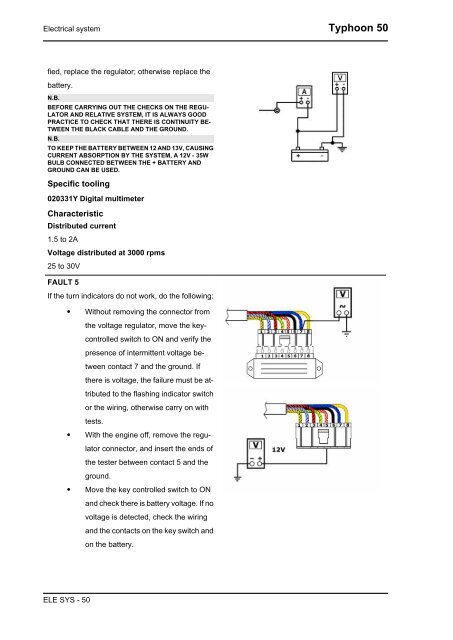
If the turn indicators do not work, do the following:<br />
• Without removing the connector from<br />
the voltage regulator, move the keycontrolled<br />
switch to ON and verify the<br />
presence of intermittent voltage between<br />
contact 7 and the ground. If<br />
there is voltage, the failure must be attributed<br />
to the flashing indicator switch<br />
or the wiring, otherwise carry on with<br />
tests.<br />
• With the engine off, remove the regulator<br />
connector, and insert the ends of<br />
the tester between contact 5 and the<br />
ground.<br />
• Move the key controlled switch to ON<br />
and check there is battery voltage. If no<br />
voltage is detected, check the wiring<br />
and the contacts on the key switch and<br />
on the battery.<br />
ELE SYS - <strong>50</strong>