
Create successful ePaper yourself
Turn your PDF publications into a flip-book with our unique Google optimized e-Paper software.
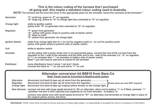
This is the colour coding of the harness that I purchased<br />
all going well, this maybe a st<strong>and</strong>ard colour coding used in Australia.<br />
NOTE! The harness did not have the wires in the appropriate place for the ammeter, hence the comment at the Ammeter**<br />
<strong>Generator</strong><br />
Charge light<br />
Regulator<br />
Ignition Switch<br />
Coil<br />
Ammeter<br />
Distributer<br />
“F” small lug green to “F” on regulator<br />
“D” large lug yellow to “D” to charge light then extended to “D” on regulator<br />
white to ignition switch<br />
yellow from “D” on generator then extended to “D” on regulator<br />
“F” green from generator<br />
“A” yellow with green stripe to positive side of starter switch<br />
“E” black to earth<br />
“D” yellow from generator via charge light<br />
white from charge light then to + on coil for negative earth or - on coil for positive earth<br />
yellow with green stripe to positive side of starter switch<br />
white to ignition switch<br />
cut the yellow with a green stripe wire in an appropriate place, connect the end of the cut wire from the<br />
regulator to the + side of the ammeter <strong>and</strong> the other end to the - side of the ammeter (i.e. “A” on regulator<br />
to “+” on ammeter then “-” on ammeter to battery side of starter switch<br />
Note!** you will need to add wire to extend to the ammeter<br />
some distributers have 2 wires 1 red <strong>and</strong> 1 black.<br />
connect the black to “-” on coil <strong>and</strong> red to “+” on coil.<br />
<strong>Alternator</strong><br />
Regulator<br />
Charge light<br />
<strong>Alternator</strong> conversion kit B8810 from Bare-Co<br />
Note! Tractor must be Converted to Negative earth system<br />
disconnect (cut back & tape up) all wires from the generator..........................<br />
}<br />
disconnect (cut back & tape up) all wires from the regulator........................... these wires are now NOT required<br />
disconnect (cut back & tape up) original yellow wire(s) on the charge light.<br />
New Harness connect red wire with large spade terminal to “B+ on alternator, other end to battery “+” or if fitted, ammeter “+”<br />
((another red wire is then required (not supplied) to run from ammeter - to battery +))<br />
connect new yellow wire with small spade terminal to “D+” on alternator <strong>and</strong> terminate on charge light in place of<br />
the original yellow wire(s) Job Done.<br />
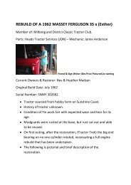
Disclaimer: While I have done my best to ensure acsuracy on these eight pages, no responsibility is accepted for errors or omissions of information