Create successful ePaper yourself
Turn your PDF publications into a flip-book with our unique Google optimized e-Paper software.
OUTPUT CIRCUIT<br />
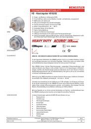
TECHNICAL DATA<br />
FUNCTION<br />
<strong>Output</strong><br />
Alarm<br />
Encoder<br />
<strong>Output</strong> NPN - open collector<br />
<strong>Output</strong> load max. 5 mA/24 V at U B = 5 VDC<br />
5mA/32 V at U B = 10...30 VDC<br />
<strong>Output</strong> Level <strong>Output</strong> active (failure condition): L ≤ 0.7 VDC<br />
<strong>Output</strong> inactive: highohmic (if necessary: get H-level by<br />
an external <strong>pull</strong>-up resistor)<br />
Malfunction indication time ≥ 20 ms<br />
The rotary encoders are equipped with an electronic monitoring system which reports<br />
malfunctions via a separate alarm output.<br />
The alarm output can be used for selecting an optical display (LED; for circuit, see above) or<br />
the control system (SPC or similar).<br />
Moreover, the alarm outputs of several encoders can be interconnected to a common<br />
“systems alarm” by means of a parallel connection. The following malfunctions are indicated:<br />
Category I Category II Category III<br />
- damaged disks - overtemperature - voltage range<br />
1 VDC < U < 4 VDC<br />
- defective LED - overload (e. g. - voltage drop on the<br />
due to short circuit) supply lines<br />
- contamination<br />
Category I malfunctions cannot be corrected; the encoder must be replaced.<br />
Category II malfunctions are detected by means of a thermal monitoring unit in the electronic<br />
system. The alarm message is cleared after the cause of temperature increase has been<br />
removed.<br />
Category III malfunctions indicate insufficient supply voltage. Also included in this category<br />
are transients in the supply voltage, e.g. due to electrostatic discharge, which may distort the<br />
output signals.<br />
This is corrected by<br />
- readjustment to the correct voltage<br />
- eliminating the cause of disturbance, i.e. by careful arrangement of the cables.<br />
58 Shaft Encoders 2001 ENCODERS COUNTERS CONTROLLERS INDICATORS RELAYS PRINTERS CUTTERS