resistance welding
resistance welding
resistance welding

Create successful ePaper yourself
Turn your PDF publications into a flip-book with our unique Google optimized e-Paper software.
esistance <strong>welding</strong><br />
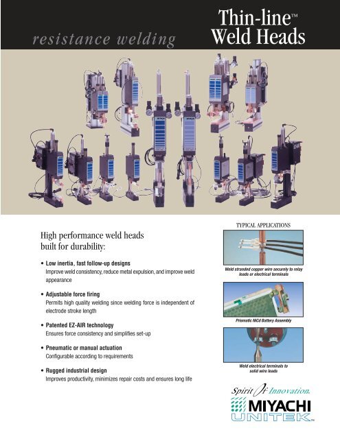
High performance weld heads<br />
built for durability:<br />
• Low inertia, fast follow-up designs<br />
Improve weld consistency, reduce metal expulsion, and improve weld<br />
appearance<br />
• Adjustable force firing<br />
Permits high quality <strong>welding</strong> since <strong>welding</strong> force is independent of<br />
electrode stroke length<br />
• Patented EZ-AIR technology<br />
Ensures force consistency and simplifies set-up<br />
• Pneumatic or manual actuation<br />
Configurable according to requirements<br />
• Rugged industrial design<br />
Improves productivity, minimizes repair costs and ensures long life<br />
Thin-line <br />
Weld Heads<br />
TYPICAL APPLICATIONS<br />
Weld stranded copper wire securely to relay<br />
leads or electrical terminals<br />
Prismatic NiCd Battery Assembly<br />
Weld electrical terminals to<br />
solid wire leads
Precision Performance through Intelligent Design<br />
The Thin-Line Ranges<br />
Miyachi Unitek’s Thin-Line Weld Heads<br />
consist of three families of full-featured<br />
products for precision metals joining:<br />
80 Series – 20 lb. (89N)<br />
40 lb. (178N)<br />
180 Series – 100 lb (445 N)<br />
90 Series – 150 lb (667N)<br />
All are precision, low inertia, force-fired<br />
designs, with a narrow vertical profile. They<br />
are ideal for both production line and bench<br />
applications and can operate at speeds<br />
greater than 3600 welds per hour.<br />
Durable High Quality Design<br />
Rugged construction, linear ball bearing<br />
bushings and an over-sized, anti-rotation<br />
bearing system provide perfect linear travel<br />
of the upper electrode arm. This system<br />
Opposed<br />
Configuration<br />
Top and bottom electrodes are<br />
used to hold the parts and<br />
provide the current path. An<br />
opposed weld is preferred over<br />
other configurations because it<br />
is easier to set-up and control<br />
the current path. It should be<br />
used whenever possible.<br />
Series<br />
Configuration<br />
Using two top electrodes, a<br />
series weld can be used when<br />
there is no access to the bottom<br />
part. Both electrodes contact<br />
the top part and current is<br />
passed through the top part to<br />
the bottom part. Two weld<br />
spots are produced, one under<br />
each electrode. Independent force control allows for separate<br />
adjustment of each electrode force and is used to balance the heat<br />
between the two weld spots.<br />
2<br />
minimizes the potential for electrode wiping<br />
action during the weld, even at maximum<br />
force settings. Based on actual test data,<br />
bearing life exceeds 25 million operations<br />
when used according to the specifications.<br />
High Speed Capability<br />
A top-mounted air actuation system, with a<br />
regulator and dual flow controls, ensures<br />
repeatable, reliable, high-speed operation in<br />
automated applications.Threaded holes on the<br />
back of the heads make them easy to mount,<br />
without their post or base, in automated<br />
work stations. EZ-AIR provides unsurpassed<br />
repeatability and ease of set-up.<br />
Precision Control<br />
Thin-Line Weld Heads add consistency and<br />
control to complex <strong>welding</strong> applications.<br />
Opposed Weld<br />
Step<br />
Configuration<br />
Thin-Line weld heads designed<br />
for series <strong>welding</strong> can also be<br />
set up in a step configuration.<br />
Two top electrodes are used,<br />
but one electrode contacts the<br />
top part and the other electrode<br />
contacts the bottom part.A single<br />
weld is produced at the part<br />
to part interface. Independent force control allows the electrode force<br />
on the bottom part to be set much higher than the force on the top part.<br />
Parallel Gap<br />
Configuration<br />
Parallel gap <strong>welding</strong> results in a<br />
single weld spot under the gap<br />
between the electrodes. It is<br />
used to weld very small parts.<br />
Two styles of parallel gap<br />
electrodes are available:<br />
Their low inertia designs ensure the fast<br />
dynamic response required for the electrodes<br />
to follow the minute expansion and contraction<br />
of the weld joint as it heats and cools. A<br />
differential motion force-firing system<br />
initiates the <strong>welding</strong> control at the precise<br />
moment when the pre-set electrode force is<br />
applied to the workpieces.<br />
Electrodes and Accessories<br />
A complete line of accessories and electrodes<br />
are available. Refer to the accessories data<br />
sheet 991-160. Optics are available for all<br />
heads. All heads are supplied with <strong>welding</strong><br />
cables, firing switch cables, mounting<br />
hardware, and one set of electrodes.<br />
Electrode Configurations Match Specific Application Needs<br />
Step Weld<br />
Unitips ® which are permanently<br />
bonded together with an<br />
insulating spacer and fixed gap; and Unibond Electrodes ® Series Weld Parallel Gap Weld<br />
which allow<br />
for adjustment of the gap.
High Quality, Full Featured<br />
The 80 Series (below), 180 Series, and 90<br />
Series are subjected to environmental life<br />
testing designed to guarantee specifications<br />
and performance.<br />
Air actuated heads are supplied with an air<br />
pressure regulator, two flow controls which<br />
are used to independently control the up and<br />
down velocity, and a 24-volt AC solenoid<br />
(115 volts is an available option). The air<br />
actuation system includes a linear spring<br />
which ensures proper operation at low forces.<br />
EZ-AIR provides high repeatability and<br />
eliminates overforce. The air systems can<br />
be moved to other locations when the<br />
heads are incorporated in work stations or<br />
automated systems. The heads can be<br />
supplied with an optional Hall Effect Limit<br />
Switch Kit, which will detect when the head<br />
is in the up or down position. This feature<br />
can prevent damage when automated<br />
machine tooling is indexed.<br />
80 Series Design Features<br />
3
80 Series Thin-Line Weld Heads<br />
80 Series Thin-Line Weld Heads – Force Range 0.25 to 20 Lbs.(1.1 to 89 N)<br />
FEATURE UNIT OF MEASURE<br />
Standard Model 80F1 80A 86F2 86A2 87F1 87A 88F 88A<br />
EZ-AIR Model (Complete Weld Head)3 80A/EZ 86A/EZ 87A/EZ 88A/EZ<br />
Actuation Manual Air Manual Air Manual Air Manual Air<br />
Weld Force Maximum lbs (N) 20 (89) 20 (89) 20 (89) 20 (89) 20 (89) 20 (89) 20 (89) 20 (89)<br />
Minimum lbs (N) .25 (1.1) .5 (2.2) .25 (1.1) .5 (2.2) .25 (1.1) .5 (2.2) .5 (2.2) .5 (2.2)<br />
Maximum Rating KVA (Watt-Seconds) 2 (250) 2 (250) 1 (125) 1 (125) 2 (125) 2 (125) 5 (250) 5 (250)<br />
Maximum Electrode Stroke Inch (mm) 1 (25) 1 (25) 1 (25) 1 (25) 1 (25) 1 (25) 1 (25) 1 (25)<br />
Electrode Diameter Inch (mm) .125 (3.2) .125 (3.2) Unibond Unibond Thermodes Thermodes 0.245 (6.2) 0.245 (6.2)<br />
Unitips Unitips<br />
Electrode Configuration Opposed Opposed Parallel Gap Parallel Gap Parallel Gap N/A Series Series<br />
Electrode Holder Type Offset Offset Offset Offset Offset Offset Offset Offset<br />
Maximum Throat Size (H x D) Inch 1.94 x 6.0 1.94 x 6.0 3.38 x 5.19 3.38 x 5.19 2.55 x 5.25 2.55 x 5.25 6.2 x 6.25 6.2 x 6.25<br />
(mm) (49 x 152) (49 x 152) (86 x 132) (86 x 132) (65 x 133) (65 x 133) (157 x 159) (157 x 159)<br />
Maximum Gap between Electrodes Inch – – 0.040 0.040 0.040 0.040 1.75 1.75<br />
(mm) – – (1.0) (1.0) (1.0) (1.0) (44.5) (44.5)<br />
Electrode Series ES-0400 ES-0400 EU or UT EU 174 or UT 174 ES-0800E ES-0800E<br />
Weld Cable Size & Length AWG #2 #2 #2 #2 #2 #2 #2/0 #2/0<br />
Inch (cm) 11 (28) 11 (28) 11 (28) 11 (28) 11 (28) 11 (28) 11 (28) 11 (28)<br />
Foot Pedal Model CP – CP – CP – MSP –<br />
Footswitch Model – – FSAC, FS1L, – FSAC, FS1L – FSAC, FS1L – FSAC, FS1L<br />
FS2L FS2L FS2L FS2L<br />
Air Solenoid Voltage VAC – 24 or 115 – 24 or 115 – 24 or 115 – 24 or 115<br />
Air Pressure for Maximum Force psig (bar) – 65 (4.5) – 65 (4.5) – 65 (4.5) – 65 (4.5)<br />
Air Cylinder Inside Diameter Inch (mm) – .75 (19) – .75 (19) – .75 (19) – .75 (19)<br />
Cycle Rate: @ Minimum Force Full Strokes/sec – 1 – 1 – 1 – 1<br />
@> 20% of Rated Force Full Strokes/sec – 2.5 – 2.5 – 2.5 – 2.5<br />
Maximum Dimensions Height – Inch (mm) 13.7 (348) 16.3 (414) 16 (406) 16.5 (419) 16 (406) 16.5 (419) 16.7 (424) 19.3 (490)<br />
(including stand & Air Kit) Depth – Inch (mm) 7.6 (193) 9.0 (229) 7.6 (193) 9.1 (231) 7.0 (178) 9.1 (231) 13.5 (343) 13.5 (343)<br />
Width – Inch (mm) 1.7 (43) 4.6 (117) 2.2 (56) 4.7 (119) 2.2 (56) 4.7 (119) 4 (102) 10.5 (267)<br />
Weight (before packing) Lbs (kg) 5 (2.3) 7 (3.2) 5.5 (2.5) 7 (3.2) 5.5 (2.5) 7 (3.2) 14 (6.4) 17 (7.7)<br />
(1) Model 80FLF and 87FLF have a force range of 0.25 - 10 lbs (1.1 - 44.5N).<br />
(2) Model 86FRE and 86ARE use 1/8 inch (3.2mm) diameter Series E0-0400 35° Offset Electrode Holders and Electrodes.<br />
(3) See page 7 for EZ-AIR specifications.<br />
(4) 17BM, 17F, 17M, 17P or 17SR<br />
80A/EZ<br />
4<br />
Offset/Opposed<br />
(See EZ-AIR)<br />
86F 88A/EZ<br />
Offset/Parallel Gap Offset /Series<br />
(See EZ-AIR)
80 Series Thin-Line Weld Heads – Force Range 4 to 40 Lbs. (18 to 178 N)<br />
(1) Model 82A is the same as Model 83A with the mounting stand, lower electrode holder and lower electrode omitted.<br />
(2) See page 7 for EZ-AIR specifications.<br />
82A 83A/EZ<br />
In-Line/Opposed In-Line/Opposed<br />
(See EZ-AIR)<br />
80 Series Thin-Line Weld Heads<br />
FEATURE UNIT OF MEASURE<br />
Standard Model 82A1 83F 83A 84F 84A 89F 89A<br />
EZ-AIR Model (Complete Weld Head)2 83A/EZ 84A/EZ 89A/EZ<br />
Actuation Air Manual Air Manual Air Manual Air<br />
Weld Force Maximum lbs (N) 40 (178) 40 (178) 40 (178) 40 (178) 40 (178) 40 (178) 40 (178)<br />
Minimum lbs (N) 6 (27) 4 (18) 6 (27) 4 (18) 6 (27) 4 (18) 6 (27)<br />
Maximum Rating KVA (Watt-Seconds) 5 (250) 5 (250) 5 (250) 5 (250) 5 (250) 5 (250) 5 (250)<br />
Maximum Electrode Stroke Inch (mm) 1 (25) 1 (25) 1 (25) 1 (25) 1 (25) 1 (25) 1 (25)<br />
Electrode Diameter Inch (mm) .25 (6.4)/ .25 (6.4)/ .25 (6.4) .25 (6.4) .25 (6.4) 0.245 (6.2) 0.245 (6.2)<br />
.125 (3.2) .125 (3.2) .125 (3.2)<br />
Electrode Configuration Opposed Opposed Opposed Opposed Opposed Series Series<br />
Electrode Holder Type In-Line In-Line In-Line Offset Offset Offset Offset<br />
Maximum Throat Size (H x D) Inch N/A 1.8 x 3.1 1.8 x 4.8 3.3 x 6.1 3.3 x 7.8 8.7 x5.6 8.7 x 8.2<br />
(mm) (46 x 79) (46 x 122) (84 x 155) (84 x 198) (221 x 142) (221 x 208)<br />
Maximum Gap between Electrodes Inch – – – – – 1.75 1.75<br />
(mm) – – – – – (44.5) (44.5)<br />
Electrode Series ES-0800/ ES-0800/ ES-0800/ ES-0800 ES-0800 ES-0800E ES-0800E<br />
ES-0400 ES-0400 ES-0400<br />
Weld Cable Size & Length AWG #2/0 #2/0 #2/0 #2/0 #2/0 #2/0 #2/0<br />
Inch (cm) 11 (28) 11 (28) 11 (28) 11 (28) 11 (28) 11 (28) 11 (28)<br />
Foot Pedal Model – MSP – MSP – MSP –<br />
Footswitch Model – FSAC, FS1L, – FSAC, FS1L – FSAC, FS1L – FSAC, FS1L<br />
FS2L FS2L FS2L FS2L<br />
Air Solenoid Voltage VAC 24 or 115 – 24 or 115 – 24 or 115 – 24 or 115<br />
Air Pressure for Maximum Force psig (bar) 55 (3.8) – 55 (3.8) – 55 (3.8) – 55 (3.8)<br />
Air Cylinder Inside Diameter Inch (mm) 1.0625 (27) – 1.0625 (27) – 1.0625 (27) – 1.0625 (27)<br />
Cycle Rate: @ Minimum Force Full Strokes/sec 1 – 1 – 1 – 1<br />
@> 20% of Rated Force Full strokes/sec 2.5 – 2.5 – 2.5 – 2.5<br />
Maximum Dimensions Height – Inch (mm) 16.2 (411) 17.4 (442) 20.1 (511) 16.7 (424) 19.3 (490) 21.9 (556) 24.5 (622)<br />
(including stand & Air Kit) Depth – Inch (mm) 17.7 (450) 7.9 (201) 9.6 (244) 10.0 (254) 11.9 (302) 14.6 (371) 16.0 (406)<br />
Width – Inch (mm) 4.6 (117) 2.6 (66) 4.6 (117) 2.6 (66) 4.6 (117) 4.9 (124) 10.5 (267)<br />
Weight (before packing) Lbs (kg) 5 (2.3) 7 (3.2) 9 (4.1) 8 (3.6) 10 (4.5) 20 (9.1) 23 (10.4)<br />
84A/EZ 89A/EZ<br />
Offset/Opposed<br />
(See EZ-AIR)<br />
Offset/Series<br />
(See EZ-AIR)<br />
5
180 & 90 Series Thin-Line Weld Heads<br />
180 Series Mid-Force Weld Heads<br />
Force Range 5 to 100 Lbs. (22 to 445 N)<br />
180A/EZ<br />
6<br />
Offset/Opposed<br />
(See EZ-AIR)<br />
Offset/Series<br />
(See EZ-AIR)<br />
90 Series High-Force Weld Heads<br />
Force Range 7 to 150 Lbs. (31 to 667 N)<br />
FEATURE UNIT OF MEASURE<br />
Standard Model 180F 180A 182A 188A 90A 90ADT<br />
EZ-AIR Model (Complete Weld Head)1 180A/EZ 188A/EZ<br />
Actuation Manual Air Air Air Air Air<br />
Weld Force Maximum lbs (N) 100 (445) 100 (445) 100 (445) 100 (445) 150 (667) 100 (445)<br />
Minimum lbs (N) 5 (22) 5 (22) 5 (22) 5 (22) 7 (31) 7 (31)<br />
Maximum Rating KVA (Watt-Seconds) 20 (875) 20 (875) 20 (875) 20 (875) 30 (1000) 20 (875)<br />
Maximum Electrode Stroke Inch (mm) 1.25 (32) 1.25 (32) 1.25 (32) 1.25 (32) 1.5 (38) 1.5 (38)<br />
Electrode Diameter Inch (mm) .25 (6.4) .25 (6.4) .25 (6.4) .245 (6.22) .25 (6.4) .25 (6.4)<br />
Electrode Configuration Opposed Opposed Opposed Series Opposed Opposed<br />
Electrode Holder Type Offset Offset In-Line Offset In-Line Offset<br />
Maximum Throat Size (H x D) Inch 6.1 x 8.5 6.1 x 11.1 2.8 x 6.3 6.0 x 11.5 2.125 x 6.2 5.75 x 11<br />
(mm) (154.9 x 215.9) (154.9 x 281.9) (71.1 x 160.0) (152.4 x 292.1) (54.0 x 157) (146.1 x 279.4)<br />
Maximum Gap between Electrodes Inch – – – 3.0 – –<br />
(mm) – – – (76.2) – –<br />
Electrode Series ES-0800 ES-0800 ES-0800 ES-0800E ES-0800 ES-0800<br />
Weld Cable Size & Length AWG #2/0 #2/0 #2/0 #2/0 #2/0 #2/0<br />
Inch (cm) 16 (41) 16 (41) 16 (41) 16 (41) 16 (41) 16 (41)<br />
Foot Pedal Model MSP – – – – –<br />
Footswitch Model – FSAC, FS1L FSAC, FS1L FSAC, FS1L FSAC, FS1L FSAC, FS1L<br />
FS2L FS2L FS2L FS2L FS2L<br />
Air Solenoid Voltage VAC – 24 or 115 24 or 115 24 or 115 24 or 115 24 or 115<br />
Air Pressure for Maximum Force psig (bar) 60 (4.4) 60 (4.4) 60 (4.4) 60 (4.4) 60 (4.4)<br />
Air Cylinder Inside Diameter Inch (mm) 1.5 (38.1) 1.5 (38.1) 1.5 (38.1) 1.5 (38.1) 1.0625 (27) 1.0625 (27)<br />
Cycle Rate: @ Minimum Force Full Strokes/sec – 1 1 1 1 1<br />
@> 20% of Rated Force Full Strokes/sec 2 2 2 1.5 1.5<br />
Maximum Dimensions Height – Inch (mm) 24 (610) 24.75 (629) 25 (635) 24.9 (632) 31.1 (790) 31.1 (790)<br />
(including stand & Air Kit) Depth – Inch (mm) 14.9 (378) 16.5 (419) 13.4 (340) 18.1 (460) 13 (330) 16 (406)<br />
Width – Inch (mm) 3.1 (79) 6.6 (168) 6.4 (163) 6.6 (168) 6.6 (168) 6.6 (168)<br />
Weight (before packing) Lbs (kg) 18.5 (8.4) 21.5 (9.8) 21.5 (9.8) 36.5 (16.6) 37.5 (17) 38.5 (17.5)<br />
(1) See page 7 for EZ-AIR specifications.<br />
188A 90A 90ADT<br />
In-Line/Opposed Offset/Opposed
Firing Force<br />
Final Force<br />
Figure 1, above, shows an incorrect balance of firing force to air pressure set<br />
by an operator after cleaning the electrodes, on a traditional weld head,<br />
resulting in poor set-up and force control.<br />
The following series of simplified diagrams explain how the EZ-AIR weld force control system works through independent control of upper<br />
and lower air chambers.<br />
Electrode up position – air pressure in the lower chamber<br />
keeps the piston in the up position. Waste air exhausts from<br />
the upper chamber.<br />
Electrode moves down – air pressure in the upper chamber<br />
forces the piston down. Waste air exhausts from the lower<br />
chamber.<br />
EZ/DAK Dual Air Kit EZ/SAK Single Air Kit<br />
Firing Force = Final Force<br />
EZ-Air Technology<br />
The EZ-AIR weld force control system simplifies<br />
the set-up process to a single adjustment and<br />
helps prevent weld over-force by closing off<br />
the input air when the actual weld force reaches<br />
the programmed weld force level, delivering<br />
accurate force control which is repeatable<br />
across multiple weld heads without complex<br />
setup or operator training.<br />
• Firing force is important because it controls<br />
contact <strong>resistance</strong>s and, therefore, heat<br />
generation at the electrode-to-part and<br />
part-to-part interface.<br />
• Superior force control = process stability<br />
and higher production yield with reduced<br />
maintenance time.<br />
EZ-AIR insures correct set-up and good force control as seen in Figure 2,<br />
above. The Miyachi Unitek EZ-AIR requires no balancing of air pressure as the<br />
air pressure is constant once the firing force is reached.<br />
Electrode reaches weld force – both solenoid valves close<br />
within 4ms and air pressure is trapped in both the upper and<br />
lower chambers. Weld force remains constant since the air<br />
cylinder piston cannot move. Compression spring provides<br />
instantaneous follow-up.<br />
EZ-AIR force control technology is available<br />
with Miyachi Unitek Thin-Line weld heads<br />
as original equipment and as a retrofit<br />
for previously purchased Thin-Line air<br />
actuated weld heads. See the Ordering<br />
Guide for more information.<br />
7
THIN-LINE WELD HEAD ORDERING GUIDE<br />
MODEL DESCRIPTION<br />
WELD HEADS Weld head, manual or air actuation, or EZ-AIR model, please refer to Weld Head Table, pages 4, 5 and 6, for model numbers<br />
80 Series, 180 Series, 90 Series<br />
and specifications. For air actuation, add /24 for 24 VAC or /115 for 115 VAC solenoid. Example: 80A/24, Model 80A with 24<br />
VAC solenoid. For EZ-AIR model, add /EZ. Example: 80A/EZ, Model 80A with EZ-AIR.<br />
FOOT ACTUATORS Model Head Type Description<br />
FS1L Air or EZ-AIR Footswitch, single level (for all pneumatic weld heads).<br />
FS2L Air or EZ-AIR Footswitch, two level (for all pneumatic weld heads).<br />
FSAC Air (115 VAC) AC Footswitch, single level. Switches 115VAC-50/60Hz to air which does NOT have a built-in valve driver.)<br />
CP Manual Cable pedal, rated: 25 lbs., 1” stroke, with 6-foot cable (for models 80F, 86F, or 87F).<br />
MSP Manual Foot pedal, medium force swing type, rated: 100 lbs., 5:1 mechanical advantage (for models 83F, 84F, 88F, 89F, or 180F).<br />
HEAD OPTIONS Model Type Description<br />
& ACCESSORIES HS20 Option Hall effect sensor kit for 20 lb. cylinders. Includes: cylinder, clamp, and sensor. Use on 80A, 86A, 87A, 88A. 88A requires two kits.<br />
HS40 Option Hall effect sensor kit for 40 lb. cylinders. Includes: cylinder, clamp, and sensor. Use on 82A, 83A, 84A, 89A. 89A requires two kits.<br />
DFS Accessory Firing switch junction box. Connects two firing switch cables in parallel to one power supply.<br />
DFS/88 Accessory Series firing switch junction box. Connects two firing switch cables in series (included in models 88, 89, and 188).<br />
BPTL Accessory Base plate, anodized. Supports optic mounting assembly.<br />
VIEWING ACCESSORIES<br />
OMA Optic mounting assembly. Use with NIKON, and BPTL.<br />
NIKON Optic, stereo zoom, NIKON, 10X eyepiece, 0.5X auxiliary objective lens.<br />
BLFOI Fiber optic illuminator system, 115V-50/60Hz. Self-supporting<br />
gooseneck, bifurcated light pipes, focusing lenses and<br />
mounting adapter for optic mounting assembly.<br />
BLFOI/230 Fiber optic illuminator system, 230V-50/60Hz. Self-supporting<br />
gooseneck, bifurcated light pipes, focusing lenses for<br />
mounting adapter for optic mounting assembly.<br />
EZ-AIR SPECIFICATIONS<br />
PROCESS SET-UP TOOLS<br />
FG20 Electrode force gage, 20 lb., scale 20 lb. x 0.2 lb.<br />
FG100 Electrode force gage, 100 lb., scale 100 lb. x 1 lb.<br />
FG200 Electrode force gage, 200 lb., scale 200 lb. x 2 lb.<br />
FG10KG Electrode force gage, 10 kg., scale 10 kg. x 0.1 kg.<br />
FG100KG Electrode force gage, 100 kg., scale 100 kg. x 1 kg.<br />
All available with or without serial number.<br />
MISCELLANEOUS ACCESSORIES<br />
UTA Unitip adapter, allows use of Unitip electrodes in model 86.<br />
WP Work Positioner, 3-inch diameter. Height adjustable from<br />
1-7/16 to 2 inches (models 86, 87, 88, 89).<br />
DESCRIPTION SPECIFICATION<br />
Force Adjustment Range Models: 80A/EZ, 86A/EZ, 88A/EZ 1 to 20 lbs (4.4 to 89N)<br />
Force Adjustment Range Models: 83A/EZ, 84A/EZ, 89A/EZ 4 to 40 lbs (17.8 to 178N)<br />
Force Adjustment Range Models: 180A/EZ 5 to 100 lbs (22 to 445N)<br />
Valve Driver Input 24 VAC<br />
Input Air Pressure<br />
ORDERING GUIDE<br />
85 to 130 psi (482 kPa to 896 kPa), unlubricated air<br />
With a Weld Head Specify XXA/EZ where XXA is the weld head (80, 83, 84, 86, 88, 89, 180). Example: 80A/EZ for an 80 Thinline Weld Head<br />
As a Retrofit Kit Specify EZ/SAK for use with a head with a single air cylinder. Specify EZ/DAK for use with a head with dual (two) air cylinders.<br />
Your Local Representative<br />
Specifications subject to change without notice.<br />
Copyright© 2005 Miyachi Unitek Corporation. The material contained herein cannot<br />
be reproduced or used in any other way without the express written permission of<br />
Miyachi Unitek Corporation. All rights reserved.<br />
Corporate Office: 1820 S. Myrtle Ave. • P.O. Box 5033 • Monrovia, CA 91017-7133 USA<br />
Tel: (626) 303-5676 • FAX: (626) 358-8048 • E-Mail: info@miyachiunitek.com<br />
Internet http://www.miyachiunitek.com • ISO 9001 Certified Company<br />
EASTERN (USA) Sales Office:<br />
170 Cross Street<br />
Boylston, MA 01505<br />
Tel: (508) 869-0583<br />
FAX: (508) 869-0585<br />
E-Mail:<br />
eastsales@miyachiunitek.com<br />
NORTH ASIA Sales Office:<br />
Unit D, 20/F, Infotech Centre<br />
21 Hung To Road<br />
Kwun Tong, Hong Kong<br />
Tel: +852 2833-6998<br />
FAX: +852 2833-6672<br />
E-Mail:<br />
asiapacific@miyachiunitek.com<br />
UNITEK EAPRO:<br />
Schootense Dreef 21<br />
NL-5708 HZ Helmond<br />
The Netherlands<br />
Tel: +31 492-54-22-25<br />
FAX: +31 492-53-62-22<br />
E-Mail: info@unitekeapro.com<br />
991-100 10/05