March 3 - 5,1999, Karlsruhe, Germany - FZK
March 3 - 5,1999, Karlsruhe, Germany - FZK
March 3 - 5,1999, Karlsruhe, Germany - FZK

Create successful ePaper yourself
Turn your PDF publications into a flip-book with our unique Google optimized e-Paper software.
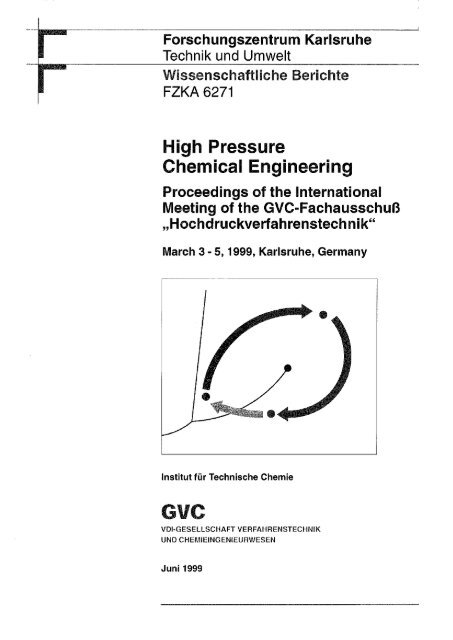
Forschungszentrum <strong>Karlsruhe</strong><br />
Technik und Umwelt<br />
Wissenschaftliche Berichte<br />
<strong>FZK</strong>A 6271<br />
High Pressure<br />
Chemical Engineering<br />
Proceedings of the International<br />
Meeting of the GVC-Fachausschuß<br />
„Hochdruckverfahrenstechnik"<br />
<strong>March</strong> 3 - 5,<strong>1999</strong>, <strong>Karlsruhe</strong>, <strong>Germany</strong><br />
Institut für Technische Chemie<br />
G V C<br />
VDI-GESELLSCHAFT VERFAHRENSTECHNIK<br />
UND CHEMIEINGENIEURWESEN<br />
Juni <strong>1999</strong>
Forschungszentrum <strong>Karlsruhe</strong><br />
Technik und Umwelt<br />
Wissenschaftliche Berichte<br />
<strong>FZK</strong>A 6271<br />
High Pressure Chemical Engineering<br />
Proceedings of the International Meeting<br />
of the GVC-Fachausschuß "Hochdruckverfahrenstechnik"<br />
<strong>March</strong> 3-5,<strong>1999</strong>, <strong>Karlsruhe</strong>, <strong>Germany</strong><br />
N. Dahmen, E. Dinjus (Editors)<br />
Institut für Technische Chemie<br />
Forschungszentrum <strong>Karlsruhe</strong> GmbH, <strong>Karlsruhe</strong><br />
<strong>1999</strong>
Als Manuskript gedruckt<br />
Für diesen Bericht behalten wir uns alle Rechte vor<br />
Forschungszentrum <strong>Karlsruhe</strong> GmbH<br />
Postfach 3640, 76021 <strong>Karlsruhe</strong><br />
Mitglied der Hermann von Helmholtz-Gemeinschaft<br />
Deutscher Forschungszentren (HGF)<br />
ISSN 0947-8620
Scientific Committee<br />
Prof. Dr. E. Dinjus, <strong>Karlsruhe</strong><br />
Prof. em. Dr. Dr. h.c. E.U. Franck, <strong>Karlsruhe</strong><br />
Prof. Dr.-lng. G. Brunner, Hamburg-Harburg<br />
Prof. Dr.-lng. G. Luft, Darmstadt<br />
Dr. S. Maier, Ludwigshafen<br />
Organization Committee<br />
Forschungszentrum <strong>Karlsruhe</strong><br />
Institut für Technische Chemie<br />
Chemisch-Physikalische Verfahren<br />
P.O.Box 3640<br />
D-76021 <strong>Karlsruhe</strong>, <strong>Germany</strong><br />
Prof. Dr. E. Dinjus,<br />
Dr. N. Dahmen<br />
Dipl.-Ing. A. Kögel<br />
Dipl.-Chem. K. Wagner<br />
E. Schröder<br />
S. Bolz<br />
Sponsors<br />
B.E.S.T. Ventil+Fitting GmbH<br />
DRÄGER TESCOM<br />
FISHER ROSEMOUNT GmbH & Co.<br />
Ernst Haage Apparatebau GmbH & Co. KG<br />
Kempe Apparate und Maschinenbau<br />
NWA analytische Meßgeräte GmbH<br />
SCHMIDLIN Labor + Service GmbH<br />
Schmidt, Kranz & Co. GmbH<br />
SITEC-Sieber Engineering AG<br />
WAGNER Meß- und Regeltechnik GmbH<br />
GVC - VDI-Gesellschaft<br />
Verfahrenstechnik und<br />
Chemieingenieurwesen<br />
P.O.Box 101139<br />
D-40002 Düsseldorf, <strong>Germany</strong><br />
Dipl.-Ing. K. O. Schaller<br />
Dipl.-Ing. R. Briel
Tagungsband der internationalen GVC-Fachausschußsitzung<br />
„Hochdruckverfahrenstechnik", 3.-5. März <strong>1999</strong> in <strong>Karlsruhe</strong><br />
Die VDI-Gesellschaft Verfahrenstechnik und Chemieingenieurwesen (GVC) ist die<br />
Fachorganisation der auf dem Gebiet der Verfahrenstechnik und des Chemieingenieurwesens<br />
tätigen Ingenieure sowie der ihnen nahestehenden Berufsgruppen. Das<br />
Rückgrat der technisch-wissenschaftlichen Arbeit der GVC stellen die über 30 Fachausschüsse<br />
dar, in deren Sitzungen ein Erfahrungsaustausch zwischen Spitzenfachleuten<br />
aus den Universitäten und der Industrie stattfindet. Jüngeren Wissenschaftlern<br />
wird Gelegenheit gegeben, ihre Arbeiten zu präsentieren und auch noch<br />
nicht ausgereifte Überlegungen zur Diskussion zu stellen.<br />
Der Fachausschuß „Hochdruckverfahrenstechnik", z.Zt. unter Vorsitz von Prof. Dr.lng.<br />
G. Brunner, Technische Universität Hamburg-Harburg, tagt im jährlichen Wechsel<br />
an Hochschulen oder Forschungseinrichtungen, die sich mit Forschung und Entwicklung<br />
auf dem Gebiet der Anwendung hoher Drücke in der Technik beschäftigen.<br />
Die GVCVDI veranstaltete seine diesjährige Fachausschußsitzung „Hochdruckverfahrenstechnik"<br />
zusammen mit dem Institut für Technische Chemie, Bereich Chemisch-Physikalische<br />
Verfahren im Forschungszentrum <strong>Karlsruhe</strong>, um den technischen<br />
Stand und wissenschaftliche Erkenntnisse zur Entwicklung von Hochdruckverfahren<br />
vor einem internationalen Publikum, vor allem aus Europa, zu präsentieren<br />
und zu diskutieren. Unter den 35 akzeptierten Vorträgen und 31 Postern fanden<br />
sich 19 bzw. 7 Beiträge aus Europa und den USA. Die Zahl der Teilnehmer betrug<br />
etwa 170, etwa 50 von ihnen kamen aus dem vorwiegend europäischen Ausland.<br />
Eingeladene Vorträge wurden zu den Themenschwerpunkten Polymerisation und<br />
Polymermodifikation in nah- und überkritischen Fluiden (Prof. E. Kiran, University of<br />
Maine, Orono, USA), Reaktionen in heißem Hochdruckwasser (SCWO, Dr. H.<br />
Schmieder, Forschungszentrum <strong>Karlsruhe</strong>, D) und Herstellung von kleinskaligen<br />
Teilchen (Prof. E. Weidner, Ruhr-Universität Bochum, D) sowie zu den für viele<br />
Verfahrensentwicklungen notwendigen Grundlagen zu Phasengleichgewichten und<br />
Mischphasenthermodynamik (Prof. V. Majer, Universite Blaise Pascal/C.N.R.S., Aubiere,<br />
F) gehalten. Weitere Themenschwerpunkte waren der Einsatz überkritischer<br />
Fluide in chemischen Reaktionen, zu Werkstoffen, zur Naturstoffbehandlung und in<br />
Trenntechniken.
Proceedings of the International GVC-Meeting on „High Pressure<br />
Chemical Engineering", <strong>March</strong> 3-5,<strong>1999</strong>, <strong>Karlsruhe</strong>, <strong>Germany</strong><br />
The VDI-Gesellschaft Verfahrenstechnik und Chemieingenieurwesen (GVC) is the<br />
organization of engineers and related scientists in the field of process and chemical<br />
engineering. The backbone of the scientific-technical work of the GVC are the more<br />
than 30 working parties; in their annual meetings experience and knowledge are exchanged<br />
between authorities from universities and industry. Young scientists have<br />
the chance to present and to discuss their work and even not completed considerations.<br />
The working party „High Pressure Chemical Engineering", chaired by Prof. Dr.-lng.<br />
G. Brunner from the Technical University Hamburg-Harburg, meets annually at universities<br />
and other research facilities involved in research and development in the<br />
field of high pressure technical applications. This year, the GVC VDI ran this meeting<br />
in an international surrounding together with the Institut für Technische Chemie<br />
at the Forschungszentrum <strong>Karlsruhe</strong>. State of the art and recent developments and<br />
results were presented and discussed in 35 oral presentations and 31 posters; 19<br />
and 7 contributions, respectively, originated from european countries and the USA.<br />
From the 170 registrated participants 50 came mostly from european countries.<br />
Invited lectures were given to the main topics polymerization and polymer modification<br />
in near- and supercritical fluids (Prof. E. Kiran, University of Maine, Orono, USA),<br />
on supercritical water oxidation (Dr. H. Schmieder, Forschungszentrum <strong>Karlsruhe</strong>,<br />
D), on particle generation (Prof. E. Weidner, Ruhr-Universität Bochum, D) and on<br />
fundamentals of phase equilibria and thermodynamics (Prof. V. Majer, Universite<br />
Blaise Pascal/ C.N.R.S. , Aubiere, F). Further topics were concerned with the use of<br />
supercritical fluids in chemical reactions, materials, natural food processing and separation<br />
techniques.
Table of Contents<br />
Polymers<br />
Key Lecture: Polymerization and polymer modifications in near- and supercritical fluids<br />
E. Kiran, Orono, MA, USA<br />
The influence of inert gases on the high-pressure phase equilibria of copolymer-comonomer mixtures<br />
G. Luft, M. Kinzl, Darmstadt, D<br />
Free-radical polymerization in homogeneous phase of supercritical C0 2<br />
S. Beuermann, M. Buback, Ch. Isemer, C. Schmaltz, A. Wahl, Göttingen, D 19<br />
Production of elastomers in supercritical carbon dioxide<br />
T.J. de Vries, M.A.G. Vorstman, J.T.F. Keurentjes, Eindhoven, NL 25<br />
Mathematical modeling of dispersion polymerization of vinyl monomers in supercritical fluids<br />
C. Kiparissides, N. Pagalos, Ch. Chatzidoukas, Ch. Mantelis, Thessaloniki, GR 27<br />
Calculation of high pressure phase equilibria in polymer systems<br />
S. Behme, G. Sadowski, W. Arlt, Berlin, D<br />
Modeling of kinetics and structural properties in high-pressure fluid-phase polymerizations<br />
M. Buback, M. Busch, H.C.M. van Boxtel, Göttingen, D<br />
Polymer modification by supercritical impregnation<br />
O. Muth, Th. Hirth, H. Vogel, Pfinztal, D<br />
Preparation and evaluation of supercritical fluid bonded liquid chromatography stationary phase<br />
MM. Robson, R. Dmoch, I. Bromilow, K.D. Bartle, P. Myers, Leeds, UK 43<br />
Posters:<br />
Effect of cocatalysts on ethylene/1-hexene copolymerisation with metallocenes under high pressure<br />
S. Schmitz, A. Rau, G. Luft, Ch. Götz, Darmstadt, D 47<br />
Experimental investigation of phase equilibria in the system polystyrene/cyclohexane/carbon dioxide<br />
B. Bungen, G. Sadowski, W. Arlt, Berlin, D<br />
Modeling of two-phase ethylene polymerization in high pressure autoclaves<br />
P. Pladis, C. Kiparissides, Thessaloniki, GR ^5<br />
Changing of properties of glassy polymers due to diffusion of supercritical C0 2<br />
J. von Schnitzler, R. Eggers, Hamburg-Harburg, D<br />
Investigation of the sorption and swelling behavior of Polymer/C0 2 systems by combined<br />
oscillometric-gravimetric measurements<br />
H. Rave, R. Staudt, J.U. Keller, Siegen, D<br />
Light Scattering Investigations of Polydimethylsiloxane in SC-CO2<br />
T. Berger, W. Steffen, Mainz, D<br />
Materials<br />
Poster:<br />
High pressure surface plasmon- and optical waveguide spectroscopy (pressure dependence of thickness<br />
and refractive index of thin PMMA-films)<br />
W. Knoll, G. Kleideiter, M.D. Lechner, Mainz, D<br />
5<br />
1 5<br />
3 1<br />
3 5<br />
3 9<br />
5 /<br />
5 9<br />
6 3<br />
6 7<br />
7 5
Hydrothermal Treatment<br />
Key lecture: SCWO: facts and hopes<br />
H. Schmieder, J. Abeln, <strong>Karlsruhe</strong>, D 83<br />
Production of hydrogen from wet biomass by supercritical water gasification<br />
J.M.L Penninger, Hengelo, NL 89<br />
Modeling, design and scale-up of an SCWO application treating solid residues of electronic scrap<br />
using a tubular type reactor - fluid mechanics, kinetics, process envelope<br />
S. Pilz, Ulm, D 91<br />
Electrochemical aspects of inorganic film deposition from supercritical aqueous solutions<br />
/./. Brand, A.O. Sezer, Lincoln, NE, USA 97<br />
Posters:<br />
Corrosion of titanium under SCWO-conditions - Recent results<br />
N. Boukis, C. Friedrich, E. Dinjus, <strong>Karlsruhe</strong>, D 101<br />
The SCWO-destruction of organic compounds in the presence of salt in leachates from dump sites<br />
in the SUWOX-facility<br />
H. Schmidt, S. Baur, V. Casal, <strong>Karlsruhe</strong>, D 103<br />
Simulation of the thermodynamic behavior of the pure components water, oxygen, nitrogen and<br />
carbon dioxide and of their mixtures for pressures up to 300 bar and temperatures up to 600°C<br />
S. Pilz, Ulm, D 107<br />
Gasification of biomass and model compounds in hot compressed water<br />
A. Kruse, J. Abeln, E. Dinjus, M. Kluth, G. Petrich, M. Schacht, E. Sadri, H. Schmieder,<br />
<strong>Karlsruhe</strong>, D Ill<br />
Reactions<br />
The dehydration of 1,4-butanediol to tetrahydrofuran in sub- and supercritical water<br />
T. Richter, H. Vogel, Darmstadt, D 119<br />
Hydrolysis of some Kopolymers with water and carbon dioxide at high pressures and temperatures<br />
K. Liu, G. Brunner, Hamburg-Harburg, D 123<br />
Hydrogenation at supercritical conditions<br />
M. Härröd, M.-B. Macher, S. van den Hark, P. Miller, Göteborg, S 127<br />
Chemical reactions in supercritical fluids as a continuous process<br />
M. Poliakoff, F. Smail, N. Meehan, K.W. Gray, M.G. Hitzler, S.K. Ross, Nottingham, UK 131<br />
Sol-gel synthesis and characterization of various oxide aerogels and NiO and Pt supported on aerogels<br />
Z. Knez, Z Novak, Maribor, SL 133<br />
Poster:<br />
Pyrolysis and hydropyrolysis of a Turkish lignite under high pressures<br />
M. Canel, Ankara, Turkey 137<br />
Phase Equilibria and Thermodynamics<br />
Key lecture: New approaches to calculation of the Henry's constant of aqueous solutes at<br />
superambient conditions<br />
V. Majer, Clermont-Ferrand, F 145<br />
A new apparatus for the investigation of the phase behavior of dilute, binary supercritical mixtures<br />
M. Turk, A. Diefenbacher, <strong>Karlsruhe</strong>, D 151
High-pressure apparatus for phase equilibria measurements: solubility of fatty acid ethyl esters<br />
in supercritical CO2<br />
G. Charbit, C. Crampon, E. Neau, Marseille, F<br />
Static solubility measurements of natural and synthetic dyestuffs in compressed gases<br />
5 9<br />
D. Tuma, G.M. Schneider, Bochum, D I<br />
Posters:<br />
High pressure equilibria of anthracene and octacosane between supercritical fluids and adsorbents<br />
P. Harting, J. Germanus, Leipzig, D<br />
Correlation, prediction and experimental determination of gas solubilities<br />
K. Fischer, M. Wilken, J. Gmehling, Oldenburg, D<br />
Pressure dependence of intradiffusion in binary mixtures with NH 3 resp. C0 2 as one component<br />
T. Groß, N. Karger, L Chen, H.-D. Lüdemann, Regensburg, D 173<br />
Phase equilibrium (solid-liquid-gas) in binary systems of polyethyleneglycols,<br />
polyethylenedimethylether with carbon dioxide, propane and nitrogen<br />
V. Wiesmet, E. Weidner, Bochum, D<br />
Natural Food Processing<br />
Extraction of carotenoid-rich oils by supercritical CO2 and subcritical propane<br />
H. G. Daood, P.A. Biacs, V. Ulis, M.H. Gnayfeed, Budapest, H 185<br />
Extraction of natural products with superheated water<br />
A.A. Clifford, A. Basile, MM. Jiminez-Cartnona, S.H.R. Al-Salidi, Leeds, UK 189<br />
Processing carotenoid-containing liquids with supercritical C0 2<br />
R. Eggers, A. Pietsch, CA. Lockemann, F. Runge, Hamburg-Harburg, D 193<br />
Posters:<br />
Countercurrent extraction with supercritical carbon dioxide: behavior of a complex natural mixture<br />
D. Büß, G. Brunner, Hamburg-Harburg, D<br />
Supercritical C0 2-extraction for production of extracts from plant materials containing<br />
Cholagoga substances<br />
T. Gämse, R. Man, Graz, A<br />
Supercritical carbon dioxide extraction of essential oil: the case of two Romanian Lamiaceae<br />
D. Barth, L Philippon, E. Pop, Nancy, F<br />
Prepurification of Esterase EP-10 by treatment with supercritical carbon dioxide (SC-C0 2)<br />
D. -J. Steinberger, A. Gießauf, T. Gämse, R. Marr, Graz, A<br />
Supercritical fluid extraction of the oil from the Tucumä Pulp (Astrocaryum vulgare Mart.) using<br />
carbon dioxide<br />
L F.de Franca, T. Christensen, G. Brunner, Hamburg-Harburg, D 215<br />
Particle Formation<br />
Key lecture: Particle generation by high pressure spray processes<br />
E. Weidner, Bochum, D<br />
Fine phospholipid particles formed by precipitation with a compressed fluid antisolvent<br />
C. Magnan, N. Commenges, E. Badens, G. Charbit, Marseille, F 231<br />
Gas Antisolvent crystallization - from fundamentals to industrial applications<br />
A. Weber, C. Weiss, J. Tschernjaew, R. Kümmel, Oberhausen, D 235<br />
1 5 5<br />
1 6 3<br />
1 6 7<br />
1 7 7<br />
1 9 7<br />
2 0 1<br />
2 0 5<br />
2 0 9<br />
2 2 5
Posters:<br />
Understanding gas antisolvent processes of biocompatible polymers and drugs with supercritcal C0 2<br />
A. Bertucco, P. Pallado, Padova, I 239<br />
Experimental and theoretical investigations of the formation of small particles from the rapid expansion<br />
of supercritical solutions (RESS)<br />
M. Türk, B. Helfgen, S. Cihlar, K. Schaber, <strong>Karlsruhe</strong>, D 243<br />
Formation of submicron particles by rapid expansion of supercritical solutions<br />
H. Kröber, U. Teipel, H. Krause, Pfinztal, D 247<br />
Effect of process parameters on the supercritical antisolvent precipitation of microspheres of<br />
natural polymers<br />
E. Reverchon, I. De Rosa, G. Delia Porta, Salerno, I 251<br />
Separation Techniques<br />
Separation of fine chemicals through continuous supercritical fluid simulated moving bed<br />
(SF-SMB) chromatography<br />
O. Di Giovanni, W. Dörfler, M. Mazzotti, M. Morbidelli, Türich, CH 259<br />
Alcohol reduction from excess wine by supercritical CCvextraction<br />
T. Gämse, F. Steinkellner, R. Marr, Graz, A 263<br />
Hydrodynamics in countercurrent packed columns at high pressure conditions<br />
P.C. Simdes, M.J. Cebola, R. Ruivo, M. Nunes da Ponte, Monte de Caparica, P 267<br />
Synthesis of heavy hydrocarbons (C26 and C28) and purification<br />
by supercritical carbon dioxide extraction<br />
D. Barth, S. Gandolfo, A.Brembilla, D. PetitJean, M. Dirand, Nancy, F 271<br />
Present situation of research and technology of textile cleaning in compressed C0 2<br />
J. Kurz, A. Hilbink, B. Gosolits, Hohenstein, D 275<br />
Extrapolation of supercritical fluid processes from lab and pilot to production scale:<br />
problems and solutions<br />
P. Mengal, J.-Y. Clavier, M. Perrut, Champigneulles, F 279<br />
Posters:<br />
Separation of stereoisomers in a SMB-SFC plant - determination of isotherms and simulation<br />
T. Giese, A. Depta, M. Johannsen, G. Brunner, Hamburg-Harburg, D 283<br />
Hydrodynamic behavior of aqueous systems in countercurrent columns at high pressures<br />
R. Stockfleth, G. Brunner, Hamburg-Harburg, D 287<br />
Trend evaluation for supercritical applications by patent statistics<br />
E. Schütz, Trostberg, D 293<br />
Natural and forced convection in precision cleaning autoclaves<br />
V. Perrut, M. Perrut, Champigneulles, F 297<br />
Cleaning of Metal Parts and Components by Compressed Carbon Dioxide<br />
N. Dahmen, J. Schön, H. Schmieder, E. Dinjus, <strong>Karlsruhe</strong>, D 301<br />
To Revert Grinding Sludge into Oil and Metal<br />
- An Application for Supercritical Fluid Extraction in a Technical Scale -<br />
U. Leffrang, K. Büttner and R. Schwing, Wiesbaden, D 305
B.E.S.T. Ventil+Fitting GmbH<br />
Heinrich-Hertz-Str. 5a<br />
76694 Forst<br />
Tel.: 07251 /9722-0<br />
Fax: 07251/9722-50<br />
e-mail: swagelok@best-ka.de<br />
Zwei-Klemmringverschraubung<br />
Absperr- und Regulierventile<br />
Nadelventile<br />
Kugel- und Kükenhähne<br />
Hochdruckbauteile<br />
Rückschlag- und Überströmventile<br />
Filter und Filterelemente<br />
1<br />
Manometeradapter<br />
Gewindeadapter<br />
Vakuum-Produkte
Pilotanlagen<br />
- mit Rohrreaktoren (Festbett)<br />
- nach dem Schleifenprinzip<br />
- Mikroreaktoranlagen<br />
Ernst Haoge Apparatebau GmbH & Co KG,<br />
KG: Sitz Mülheim a. d. Ruhr, Amisgericht Mülheim a. d. Ruhr, HRA 451.<br />
Persönlich haftende Gesellschafterin: Ernst Haage Apparatebau Verwallungs GmbH,<br />
Sitz Mülheim a. d. Ruhr, Amtsgericht Mülheim a. d. Ruhr, HRB 2240.<br />
Geschäftsführer: Karin Hesselmann, Alfred Hesselmann, Dipl. Kfm. Thomas Hesselmann<br />
ERNST HAAGE [Hg<br />
Apparatebau GmbH & Co KG<br />
PRODUKTPROGRAMM<br />
- Laborautoklaven<br />
Inhalt 0,15-7,5 Itr.<br />
Betriebsdruck bis 350 bar<br />
Betriebstemperatur bis 500 °C<br />
- Mikroautoklav<br />
Inhalt 50 ml<br />
Betriebsdruck 350 bar<br />
Betriebstemperatur 350 °C<br />
- Sonderausführungen<br />
Inhalt bis 5.000 Itr.<br />
Betriebsdruck bis 2.000 bar<br />
Betriebstemperatur bis 800 °C<br />
- Hochdruckarmaturen<br />
Ernst Haage Apparatebau GmbH & Co KG<br />
Hauskampstraße 58 • D-45476 Mülheim an der Ruhr<br />
Telefon 0208/40302-0<br />
Telefax 0208/40302-77
Polymers<br />
3
GVC-Fachausschuß ,Jügh Pressure Chemical Engineering", <strong>March</strong> 3-5, <strong>Karlsruhe</strong>, <strong>Germany</strong>, <strong>1999</strong> <strong>FZK</strong><br />
Polymerization and Polymer Modifications<br />
in Near- and Supercritical Fluids<br />
Erdogan Kiran<br />
Department of Chemical Engineering<br />
University of Maine<br />
Orono, Maine 04469-5737<br />
E-mail: Kiran@maine.edu; Fax: 207-581-2323<br />
This presentation is a review of the current state of high-pressure polymerization and polymer modifications in<br />
near- and supercritical fluids. The topics covered include homogeneous and heterogeneous polymerizations in<br />
pure fluids and fluid mixtures; polymer modifications through polymerization within swollen matrices of host<br />
polymers; polymer modifications through chain side group modifications; and depolymerization reactions.<br />
Future directions and research needs are also presented.<br />
Introduction<br />
Polymerization is the process of converting<br />
monomer(s) to long chain molecules. It is a basic<br />
process to produce materials with<br />
"microstructural" features. The microstructural<br />
consequences of polymerization are reflected in<br />
the molecular weight, molecular weight<br />
distribution, chain end groups, repeat unit,<br />
orientation and chain regularity (as in tacticity),<br />
monomer sequence distributions (as in<br />
copolymers), branching, or crosslinking. The chain<br />
microstructure influences the ultimate properties<br />
of polymers that find ever increasing use in our<br />
everyday life.<br />
Polymerization reactions proceed either by the<br />
"step growth" or the "chain addition" mechanisms.<br />
Step-growth polymerizations require monomers<br />
with at least two functional groups and are<br />
involved in the manufacture of several industrially<br />
important polymers such as polyamides,<br />
polyesters, and in the formation of biopolymers<br />
such as polysaccharides, proteins and polypeptides<br />
in nature.<br />
The chain addition polymerizations require<br />
monomers with double bonds. They require free<br />
radical or ionic initiators to open the double bond<br />
and form the polymerization path in the<br />
manufacture of polymers such as polyethylene,<br />
polypropylene, polystyrene, and polyvinyl chloride<br />
which together constitute the majority of<br />
polymers, about 70 % of all polymers produced. A<br />
wide range of copolymers or terpolymers are<br />
5<br />
produced by chain addition polymerization of two<br />
or three different monomers with double bonds.<br />
Polymerization processes are carried out in bulk or<br />
in a solvent with or without added stabilizers, and<br />
may proceed under homogeneous or<br />
heterogeneous conditions. Polymerization in the<br />
presence of a solvent medium offers processing<br />
advantages in terms of lowered viscosity and<br />
elimination of localized heating that may lead to<br />
adverse polymerization rates. But the presence of<br />
traditional solvents introduces environmental<br />
issues in connection with solvent removal or<br />
recovery, kinetic issues related to chain transfer to<br />
solvent. Presence of stabilizers may introduce<br />
additional purity concerns if they need to be<br />
removed from the final polymer. Use of near and<br />
supercritical fluids as polymerization media is an<br />
alternative approach which may alleviate<br />
environmental issues by elimination of the use of<br />
traditional solvents, or help the solvent removal or<br />
purification steps while reducing the use of<br />
conventional solvents. Indeed, over the past 10<br />
years there has been a remarkable increase in the<br />
interest in this area.<br />
Several review articles on the use of near - or<br />
supercritical fluids as polymerization or polymer<br />
modification media have recently appeared [1-3].<br />
The motivation and the rational are varied but<br />
include the following:<br />
a) High pressures favor polymerization because<br />
polymerization usually involves a decrease in<br />
volume.<br />
GVC GVC^-+'v
) Precipitation thresholds or polymer molecular<br />
weights can be controlled because dissolving<br />
power of the supercritical fluids can be<br />
changed by density of pressure.<br />
c) Polymerization rates can be fine-tuned<br />
towards producing polymers of desired<br />
properties because the propagation or<br />
termination rates can be modulated.<br />
d) Monomer reactivity ratios may be tuned and<br />
thus monomer sequence distributions and the<br />
microstructure of copolymers may be<br />
controlled.<br />
e) Intimacy of the ion pairs in propagating chains<br />
in ionic polymerizations can be adjusted to<br />
alter the rate of polymerization, or<br />
Stereoregulation of the propagation because<br />
the dielectric constant of the reaction medium<br />
can be fine-tuned.<br />
f) Reactions may be carried out in an<br />
environmentally more acceptable manner<br />
because reactions may be conducted in fluids<br />
such as carbon dioxide (with or without<br />
stabilizer additives or co-solvents depending<br />
upon the system), and the polymer endproduct<br />
and the unreacted monomer(s) or<br />
solvents can be conveniently separated.<br />
Schemes can be devised to recover the<br />
polymer in powder form with minimal<br />
residual solvent entrapment.<br />
g) Micro-structured composites and blends can<br />
be prepared because a polymer can be swollen<br />
in a supercritical fluid permitting infusion of<br />
another monomer and its in-situ<br />
polymerization.<br />
This talk will present a state-of -the art review of<br />
the field with examples that have been selected to<br />
highlight the different methodologies that are used<br />
by different research groups (Buback at the<br />
University of Göttingen, Luft at Darmstadt<br />
University of Technology, DeSimone at University<br />
of North Carolina, Beckman at University of<br />
Pittsburgh, Kennedy at University of Akron,<br />
Watkins at University of Massachusetts, Erkey at<br />
University of Connecticut, Arai at Tohoku<br />
University, and Kiran at University of Maine). The<br />
talk is organized in two major parts. Part I will<br />
focus on polymerization reactions by chain<br />
addition and step growth mechanisms, while Part<br />
II will describe reactive modifications of polymers<br />
via side group modifications, reactive blending, or<br />
depolymerizations.<br />
6<br />
Part I. Polymerization Reactions<br />
High-pressure polymerizations where the<br />
monomer is both a reactant and a solvent<br />
Polymerization of ethylene. From a<br />
thermodynamic standpoint it has been long<br />
recognized that pressure favors polymerization.<br />
This is because successive additions of monomers<br />
to form a polymer chain normally involves a<br />
decrease in volume. Indeed, significant amount of<br />
literature exists on high-pressure polymerization in<br />
the liquid state, either in the bulk or in the<br />
presence of a liquid solvent [4, 5]. Polyethylene is<br />
historically the best example of commercial highpressure<br />
polymerization where the monomer<br />
functions both as a reactant and a solvent and the<br />
conditions are supercritical for ethylene [6], The<br />
polymerization is carried out in tubular reactors<br />
using organic peroxide initiators at temperatures<br />
above the melting temperature of polyethylene<br />
(typically in the range from 140 to 300 °C) and at<br />
pressures in the range from 1300 to 3000 bar [6-8],<br />
Polymerization is controlled not to pass the<br />
solubility limit of the polymer in the monomer. At<br />
temperatures above 115 °C and pressures above<br />
1900 bar, it is reported that miscibility of<br />
monomer and polymer is maintained at all<br />
conversions and polymerization of ethylene<br />
proceeds in the homogeneous supercritical state<br />
[6]. Miscibility and phase behavior of ethylene +<br />
polyethylene or its copolymer is receiving renewed<br />
interest and a comprehensive review has appeared<br />
[9]. A recent publication has reported on the<br />
critical points of ethylene + polyethylene wax (M<br />
1100) as a function of polyethylene<br />
concentrations up to 3.5 mol % in the temperature<br />
range of 413 to 513 K at pressure up to 93 MPa<br />
[10], Such information is especially helpful in<br />
understanding and preventing fouling which is a<br />
concern in polyethylene reactors [7, 8].<br />
A new development in polyolefin synthesis is the<br />
use of homogeneous single-site metallocene<br />
catalysts [11], which unlike traditional Ziegler-<br />
Natta catalysts contain just a single atom, usually<br />
titanium or zirconium. The catalysts are introduced<br />
in the gas, solution and emulsion processes to<br />
manufacture linear low density or high density<br />
polyethylene, isotactic polypropylene, and a host<br />
of polyethylene copolymers [12]. In<br />
homopolymerization of ethylene at 150 MPa and<br />
453 K, productivity levels of 4400 kg of<br />
polyethylene (M w of about 400,000 and PDI of
about 2 ) per gram of catalysts is reported. These<br />
homogeneous metallocene catalysts permit the<br />
synthesis of polyolefins with better control of side<br />
chains, or controlling the properties of copolymers<br />
that are inaccessible with heterogeneous Ziegler-<br />
Natta type catalysts. [Ziegler -Natta catalysts are<br />
mixtures of solid and liquid compounds containing<br />
metal atoms, such as TiCh on a carrier like Mg Cl 2<br />
together with trialkylaluminum compounds such<br />
as AIEt 3]. Miscibility of polyethylene or its<br />
copolymers produced by using metallocene<br />
catalysis are expected to receive greater attention<br />
in the coming years.<br />
Copolymerization of carbon dioxide.<br />
Copolymerization of carbon dioxide is another<br />
example where the monomer may function both as<br />
a reactant and a solvent. Historically, the interest<br />
in copolymerization of carbon dioxide has been in<br />
connection with a desire for carbon dioxide<br />
fixation [13, 14]. Recent interest however is in the<br />
use of C0 2 not only as a reactant, but also as a<br />
solvent and in the possibility of producing<br />
phosgene-free and thus environmentally desirable<br />
synthesis and recovery of polycarbonates.<br />
In a recent study [15], carbon dioxide was used as<br />
the solvent for copolymerization of propylene<br />
oxide with carbon dioxide. Polymerizations were<br />
evaluated at pressures from 300 to 1200 psi at 60<br />
°C using zinc (glutarate) catalyst. Polymerization<br />
leads to both the carbonate [-0-CO-0-] and ether<br />
[-0-] linkages in the chain. At pressures greater<br />
than 700 psi, high selectivity for poly (proylene<br />
carbonate) versus poly (propylene oxide)<br />
formation was noted, with fraction of<br />
polycarbonate linkages being in the range of 90-96<br />
%. Carbon dioxide was shown be as effective a<br />
solvent as methylene chloride for these<br />
copolymerizations in terms of selectivity for<br />
polycarbonate versus polyether (polypropylene<br />
oxide) formation.<br />
A more recent example where carbon dioxide has<br />
been used as a solvent and reactant is the<br />
copolymerization of carbon dioxide with<br />
cylohexenoxide to produce poly(cyclohexene<br />
carbonate) [16], In this study, in contrast to earlier<br />
studies, a zinc-based but fluorinated catalyst that is<br />
soluble in supercritical carbon dioxide was<br />
developed and used. The catalyst has been shown<br />
to lead to high polymer yields (as high as 69 %).<br />
Polycarbonates containing greater than 90%<br />
polycarbonate linkages with molecular weights of<br />
50,000 to 150,000 have been reported.<br />
7<br />
Free Radical Polymerizations<br />
Homogeneous Solution Polymerization in<br />
Supercritical Carbon Dioxide. These<br />
polymerizations require that the monomer, the<br />
initiator and the polymer remain in solution<br />
throughout the reaction. Because carbon dioxide is<br />
not a very good solvent for majority of polymers,<br />
homogeneous solution polymerizations have been<br />
limited to either low conversion operations, or to a<br />
few special, mostly fluorinated, monomer/polymer<br />
cases that display high solubility in carbon<br />
dioxide. A well-known example is the<br />
polymerization of 1,1 dihydroperfluorooctyl<br />
acrylate (FOA) [3, 17]. Nearly 40 wt % monomer<br />
solution in carbon dioxide with AIBN initiator at<br />
60 °C and 207 bar over 48 hr has been reported to<br />
lead to a polymer of molecular weight 270,000<br />
with polymer yield of about 65 %. Styrenes with<br />
perfluoroalkyl side chains in the para position have<br />
also been polymerized via solution polymerization<br />
in supercritical carbon dioxide by the same group.<br />
Another example is the polymerization of<br />
octafluoropentyl acrylate (OFP) with AIBN as<br />
initiator [18]. This monomer has been shown to be<br />
polymerized in carbon dioxide at 65 °C and 3000<br />
psi, resulting in a polymer with a molecular weight<br />
of Mw = 5000 , with 45 % yield.<br />
Homogeneous free-radical polymerizations of<br />
traditional monomers such as styrene start with the<br />
establishment of the phase boundaries for<br />
monomer + polymer + fluid [19]. A recent study<br />
[20]reports that to maintain homogeneous<br />
conditions in mixtures of polystyrene (11-13 %) +<br />
styrene (37-44 %) + carbon dioxide (43-51 %),<br />
one must maintain pressures higher than about 750<br />
bar at 80 °C if the molecular weight of the polymer<br />
to be produced is 10,000. These compositions<br />
represent about 20 % monomer conversion<br />
starting with about 50 % monomer containing<br />
mixtures. For higher molecular weight polymers,<br />
much higher pressures are required. At 500 bar,<br />
with 45 % carbon dioxide, maximum monomer<br />
conversion allowable is about 10 %.<br />
Heterogeneous Precipitation Polymerization. In<br />
these polymerizations, initially the monomer and<br />
the initiator are miscible in the fluid but the<br />
polymer that forms eventually phase separates.<br />
The treshhold polymer chain sustainable in the<br />
system depends on the fluid, and the P/T<br />
conditions. Phase separation is influenced by the
solubility of the polymer in the fluid + unreacted<br />
monomer which may serve as a co-solvent.<br />
Early examples include polymerization of styrene<br />
in supercritical ethane [21], propane, and butane<br />
[19, 22]. It was shown that polymerization of<br />
styrene in ethane at pressures in the range 12 to 25<br />
MPa, and temperatures in the range 333 to 343 K<br />
and concentrations Of 3.33 - 6.66 wt % resulted in<br />
polystyrenes of low molecular weight, M = 1000,<br />
and low polydispersity (PDI = 1.2) [21]. In nbutane<br />
polymerizations at 160 °C, using t-butyl<br />
peroxide initiator, polymers with molecular<br />
weights in the range M w= 11,000 to 20,000 with<br />
PDI less than 2 were obtained in the pressure<br />
range from 6.9 to 27.6 MPa. In this study, using a<br />
recirculation loop, the polymers that reach the<br />
phase separation limit at a given pressure were<br />
precipitated and separated in a trap maintained at a<br />
lower pressure, while the one homogenous phase<br />
was recompressed and recirculated.<br />
Recently, thermal and free radical precipitation<br />
polymerization of styrene has been carried out in<br />
supercritical carbon dioxide [23]. Thermal<br />
polymerizations conducted at a constant C0 2<br />
density of 1.3 show that the yield would increase<br />
from about 10 % to 40 % with temperature in the<br />
range 170 to 200 °C, while the weight average<br />
molecular weight would decrease from about<br />
40,000 to 15,000. At 200 °C, weight average<br />
molecular weight was noted to decrease from<br />
about 25,000 to 15,000 with increasing pressure<br />
from 4000 to 8000 psi. In the case of free-radical,<br />
AIBN-initiated polymerization at 65 °C and 5800<br />
psi, the weight average molecular weight was<br />
about 15,000 with PDI in the range from 1.5 to<br />
2.0.<br />
Another example is the polymerization of acrylic<br />
acid in supercritical carbon dioxide (20 wt %) with<br />
t-butyl hydroperoxide as initiator [24]. The effect<br />
of initiator concentration (2 to 6%), temperature<br />
(160 to 350 °C) and pressure (2700 to 4700 psi)<br />
have been reported The polymerizations were<br />
conducted at 250 °C and 4500 psi. Contrary to<br />
conventional free radical polymerizations, in these<br />
polymerizations, it is reported that the initiator<br />
amount does not influence the molecular weight,<br />
even though in the absence of the initiator<br />
polymerization would not proceed. No explanation<br />
for this observation has been provided. Also, at a<br />
given temperature, molecular weight was found to<br />
decrease with pressure. For example, at 160 °C<br />
weight average molecular weight decreased from<br />
8<br />
about 80,000 to 45,000 upon increase of the<br />
pressure from 2700 to 3700 psi while<br />
polydispersity was reduced from about 10 to 7.<br />
This behavior is somewhat similar to the thermal<br />
polymerization of styrene indicated above. No<br />
explanations for the unexpected pressure effect for<br />
these systems have been provided.<br />
It should be noted that in a recent study on<br />
copolymerization of carbon dioxide and propylene<br />
oxide in 1,3 dioxolane, it was also reported [25]<br />
that the yield is enhanced with pressure from 200<br />
to 600 psi, but with further increase in pressure<br />
there is a decrease in the yield. This unexpected<br />
affect of the increased pressure was attributed to<br />
the swelling (expansion) of the solvent as a result<br />
of greater dissolution of carbon dioxide in the<br />
solvent, which causes a reduction in the solubility<br />
of the copolymer. At pressures greater than 600<br />
psi, molecular weight of the polymer was observed<br />
to decrease also.<br />
These observations point to the complex nature of<br />
the phase behavior of these systems and possible<br />
solubility maximum for the polymer in the binary<br />
fluid system consisting of monomer plus carbon<br />
dioxide.<br />
Heterogeneous Precipitation Polymerization in<br />
Binary Fluid Mixtures - Density modulation and<br />
Levitation. A recent approach in polymerization<br />
studies is the use of binary fluid mixtures of<br />
carbon dioxide with a traditional solvent to<br />
increase the precipitation thresholds and thus<br />
achieve higher molecular weights [26]. In this<br />
context AIBN initiated free-radical polymerization<br />
of styrene has been reported in mixtures of carbon<br />
dioxide with pentane, toluene and sulfur<br />
hexafluoride [26]. It has been however shown that<br />
up to 30 % level, pentane or toluene additions does<br />
not alter the relatively poor nature of the fluid<br />
mixture,as a solvent for polystyrene and molecular<br />
weights remain much lower than achievable in<br />
pure pentane or toluene. At 68 °C and 56 MPa, the<br />
weight average molecular weights of the polymer<br />
produced in toluene, pentane, or carbon dioxide<br />
are 49, 000; 29,000 and 16,000, respectively. In<br />
70/30-carbon dioxide/pentane or 70/30- carbon<br />
dioxide/toluene mixtures, the weight average<br />
molecular weights are 17,000 and 21,000. In these<br />
mixtures, the effect of pressure follows the<br />
expected trend, that is higher molecular weight<br />
polymer is obtained when pressure is increased.<br />
The polymerization trends in mixtures of carbon<br />
dioxide with SF 6 however show unique features. In
these mixtures, at a given temperature, a wide<br />
range of fluid densities are obtainable at different<br />
pressures. This was used in a novel way to conduct<br />
polymerization by matching fluid mixture density<br />
to the density of polystyrene. This is referred to as<br />
levitation polymerization. The concept is to hinder<br />
precipitation of the polymer when the molecular<br />
weight increases to a level where the polymer is no<br />
longer soluble in the medium. This helps in<br />
producing even higher molecular weights. Indeed<br />
experiments conducted at 51 and 73 °C, show a<br />
maximum in the polymer molecular weight if<br />
polymerizations were carried out at pressures that<br />
would give a fluid density close to 1.05, the<br />
density of polystsyrene. For example, at 51 °C and<br />
21 MPa, fluid density is 1.05 and the molecular<br />
weight of the polymer is 175,000.<br />
As pointed out in the previous section, molecular<br />
weight maximum with pressure has been noted in<br />
some other systems, however the fluid mixture<br />
density information for those systems have not<br />
been reported to test if density plays a key role in<br />
those system also. The notion of solubility<br />
maximum has not been evaluated for the<br />
polymerization in the SF 6+ C0 2 mixtures.<br />
The notion of levitation by density matching offers<br />
the possibility for a psuedo-dispersion<br />
polymerization process that is free of added<br />
stabilizers (such as surfactants) used in<br />
conventional dispersion polymerizations.<br />
Heterogeneous Dispersion and Emulsion<br />
Polymerization. In dispersion polymerization, the<br />
monomer and the initiator are soluble in the<br />
continuous solvent phase, the polymer phase<br />
separates but is stabilized as a colloid with<br />
stabilizer additives. Polymerization proceeds to<br />
high degrees of polymerization and the end<br />
product is recovered as spherical particles. In<br />
emulsion polymerization, the initiator is<br />
preferentially dissolved in the continuous phase<br />
and not the monomer phase, and the monomer<br />
does not have high solubility in the continuous<br />
phase.<br />
For dispersion polymerization in carbon dioxide,<br />
special stabilizer compounds have been developed.<br />
These molecules have C0 2 - philic segments that<br />
show high solubility in C0 2 and CO rphobic<br />
anchoring segments that are relatively insoluble in<br />
carbon dioxide. They are either homopolymers<br />
such as poly (FAO) which has an acrylic-like<br />
anchor and fluorinated C0 2-philic side chain, or<br />
9<br />
block copolymers of polystyrene and poly (FAO),<br />
or block copolymers of polystyrene and<br />
Poly(dimethylsiloxane) where the FOA or siloxane<br />
blocks function as the C0 2-philic segments [3, 27].<br />
Another group of stabilizers are the comblike graft<br />
copolymers, such as poly(niethylmethacrylate-cohydroxyethylmcthacryalte)-graft-poly(perfluoropropylene<br />
oxide) [28].<br />
These polymerizations have been successfully<br />
carried out in carbon dioxide with high<br />
polymerization rates to produce polymers of high<br />
molecular weight that are recovered as 1-3 micron<br />
spherical particles. For example, polymerization at<br />
65 °C and 205 bar, with PFAO as stabilizer and<br />
using AIBN as initiator, polymethyl methacrylate<br />
of Mn =200,000 to 315,000 have been produced<br />
[27]. With a comb-like stabilizer at 65 °C and 380<br />
bar polymethyl methacrylates in the molecular<br />
range 100,000 to 355,000 have been produced<br />
[28].<br />
A recent study [29] demonstrates the dependence<br />
of dispersion polymerizations on solvent quality<br />
by conducting poly(FOA)-stabilized dispersion<br />
polymerization of methyl methacrylate in<br />
supercritical carbon dioxide in the presence of<br />
different amounts of added helium. It is shown that<br />
in the presence of helium, higher molecular weight<br />
polymer, higher yields, smaller particles sizes and<br />
a narrower particle size distributions are obtained.<br />
At 65 °C and 344 bar, polymer produced in pure<br />
carbon dioxide has a molecular weight of 204,000,<br />
and a particle size and particle size distribution of<br />
1.93 microns and 1.29. In the presence of 10 mole<br />
% helium, molecular weight becomes 365,000,<br />
particle size reduces to 1.64 microns with a<br />
particle size polydispersity of 1.06. It is argued<br />
that in the presence of He, solvent quality is<br />
reduced, and as a result, critical chain length of<br />
PMMA in the continuous phase is reduced, and the<br />
polymer chain nucleates more effectively. When<br />
more nuclei are stabilized, a reduction in particle<br />
size is observed. Higher conversions and higher<br />
molecular weights in C0 2 + He mixtures are<br />
attributed to lower degree of swelling which in<br />
terns leads to higher viscosity and gel effect.<br />
Ionic Polymerizations<br />
Ionic polymerizations are either cationic where<br />
polymerization proceeds by adding monomers to a<br />
terminal carbocation, or anionic where monomers<br />
add to a negatively charged terminal carbon.
Cationic polymerizations are normally conducted<br />
at low temperatures to (-10 to -100 °C) in<br />
chlorinated hydrocarbon solvents that have<br />
sufficient polarity to promote active ion<br />
generation. Recently carbocationic polymerization<br />
of isobutylene in supercritical carbon dioxide has<br />
been reported. It has been demonstrated that at<br />
32.5°C and 120 bar, using an initiator system of 2chloro-2,4,4<br />
trimethyl pentane / SnCl 4 or TiCl 4,<br />
isobutylene could be polymerized with 30 %<br />
conversion and result in a polymer with Mn =<br />
2000 and PDI = 2 [30], Other systems that have<br />
been reported include polymerization of 3-methyl-<br />
1-butene and 4-methyl-l-pentene and synthesis of<br />
phenol terminated polyisobutylene [31].<br />
Some preliminary experiments on cationic<br />
dispersion polymerization of isobutylene in<br />
supercritical carbon dioxide in the presence of<br />
polymeric surfactants has also been reported [32].<br />
Step-Growth Polymerizations<br />
Even though not as extensive as chain addition<br />
polymerization, polymerization by step growth<br />
mechanisms in supercritical fluid media is also<br />
gaining attention.<br />
By devising supercritical fluid based schemes to<br />
remove the byproduct from the condensation<br />
reactions, higher conversions are achievable. Even<br />
though water does not show high solubility in<br />
supercritical carbon dioxide, other condensation<br />
products (i.e., phenol, acetic acid) which may have<br />
higher solubility in carbon dioxide may be<br />
extracted from the reaction mixture with carbon<br />
dioxide and increase conversation. Removal with<br />
carbon dioxide would be a desirable path<br />
compared to vacuum methods employed in<br />
traditional condensation polymerizations.<br />
In a recent study supercritical carbon dioxide has<br />
been explored as a medium for conducting melt<br />
phase transesterification of bisphenols with<br />
diphenyl carbonate to produce polycarbonate (at<br />
yields approaching 95 %) at temperatures around<br />
270 °C and pressures of about 3000-4000 psi. [33-<br />
35]. Supercritical carbon dioxide provides a means<br />
of efficient extraction of phenol, which is the<br />
byproduct of reaction, and furthermore lowers the<br />
viscosity of the molten polycarbonate for easier<br />
handling. Swelling improves also the rate of<br />
polymerization by increasing the surface area<br />
available for condensate removal.<br />
10<br />
Even though water has a low solubility in carbon<br />
dioxide, it has been shown that it can also be<br />
effectively removed with supercritical carbon<br />
dioxide in formation of nylon 66 (a polyamide)<br />
[34]. In this polyamide formation, because of the<br />
reactivity of carbon dioxide with amines, instead<br />
of using hexamethylene diamine, reaction was<br />
carried out with a nylon salt. Carbon dioxide was<br />
shown to lower the melting point of the nylon salt<br />
and permit polymerization to proceed at lower<br />
temperatures. At temperatures around 270 °C and<br />
over a reaction time of about 3 hr at 3000 psi<br />
polyamides of high molecular weight (Mn =<br />
25,000) have been produced.<br />
Part II. Polymer Modification Reactions<br />
Polymer modification through reactions in nearor<br />
supercritical water. Polymer modifications in<br />
near and supercritical fluids are being explored<br />
with different objectives.<br />
An interesting case of polymer modification<br />
involves generation of functional groups on<br />
ethylene based copolymers [36]. Recently, a<br />
methodology has been described to convert the<br />
functional groups of ethylene-acrylate, -CH (COOR)<br />
- ethylene-acrylamide -CH (CONH 2) - and ethyleneacrylonitrile<br />
-CH (CN) - copolymers into an<br />
ethylene acrylic acid -CH(COOH)- type copolymer<br />
using near critical water (at temperatures of 250<br />
and 300 °C and pressures of 300 to 1500 bar. An<br />
attractive feature of such modifications that result<br />
in reactive side groups is that these groups can<br />
then be reacted to produce terpolymers from<br />
binary copolymer materials.<br />
It is shown that at 300 °C and 300 bar, nitrite<br />
group of butadiene-acrylonitrile copolymers are<br />
essentially all converted to amide (about 15 %)<br />
and acid groups (about 85 %) within about 4<br />
hours. Mechanistically the nitrile groups are first<br />
converted to amide which is further hydrolized to<br />
the acid groups. In the case of ethylenemethlyacrylate<br />
copolymers, the ester groups were<br />
converted to acid groups in one step almost<br />
quantitatively at 275 °C and 300 bar within about 3<br />
hrs. With ethylene-butyl acrylate copolymers<br />
conversion was slow, and after 60 hrs at 250 °C<br />
and 1500 bar, the content of -COOH groups<br />
reaching 80 % with acrylate groups remaining<br />
being at 20 %. These reactions are reported to
proceed mostly under heterogeneous conditions,<br />
and it is indicated that full exploration of the<br />
potential modifications would require<br />
documentation of the phase behavior.<br />
Another important area of polymer modification<br />
with subcritical and supercritical water is the<br />
hydrolysis of polycondensation polymers such as<br />
polyethylene terephthalate (PET), polyurethanes,<br />
and nylons for conversion to their monomers [ 37],<br />
Specifically, in supercritical water, 91 % monomer<br />
recovery (terephthalic acid) is achieved at 400 °C<br />
and 40 MPa in less than 15 min reaction times<br />
[38], Studies of these reactions using a<br />
hydrothermal diamond anvil cell to follow the<br />
phase changes during the reaction of PET in water<br />
demonstrate the complexities in terms of<br />
simultaneous reaction and dissolution processes.<br />
Unlike polycondensation polymers, polymers of<br />
addition polymerization such as polyethylene and<br />
polypropylene when depolymerized in inert<br />
atmosphere (39) or in supercritical water (37) do<br />
not convert to just the monomer but, but a<br />
homologous series of oligomers (alkanes and<br />
alkenes). Compared to pyrolysis in argon, for<br />
polyethylene, the portion of the lighter products<br />
increases in supercritical water depolymerizations<br />
conducted at 693 K and water densities of 0.13 and<br />
0.42 g/cm3. The 1-alkene to n-alkane ratio also<br />
increases in supercritical water and with density.<br />
These are attributed to the fact that in argon<br />
pyrolysis, the reaction proceed in the molten state<br />
of the polymer, whereas in supercritical water,<br />
some of degradation products are dissolved in<br />
supercritical water and further decomposes to<br />
smaller fragments, leading to differences in the<br />
reaction phase. Mechanistically, the increased<br />
alkene amount suggests that in supercritical water<br />
beta-sicssion is more prevalent than hydrogen<br />
abstraction reactions in the decomposition paths<br />
[37, 39].<br />
These studies point to the possibilities for using<br />
supercritical fluids as reaction media to control<br />
product distributions.<br />
Another example of polymer modification reaction<br />
is the hydrolysis of cellulose in subcritical and<br />
supercritical water [40], Cellulose is shown to<br />
hydrolyze rapidly (
which is then polymerized. Phase morphologies<br />
different than melt-mixing or blending are<br />
produced. For example, if the polymer is<br />
semicrystalline, swelling with carbon dioxide<br />
opens up primarily the amorphous regions, and the<br />
polymerization proceeds in the amorphous domain<br />
of the host polymer.<br />
In a recent study [47] of the polymerization of<br />
styrene in carbon dioxide swollen high density<br />
polyethylene at 100 °C and 240 atm using t-butyl<br />
peroxybenzoate as initiator has shown that more<br />
than 100 % mass uptake of polystyrene levels are<br />
reached within about 15 hr reaction time. The<br />
crystalline melting temperature of polyethylene in<br />
these blends is reported to be the same as the<br />
initial polyethylene, which is an indication of the<br />
styrene polymerization proceeding only in the<br />
amorphous regions of polyethylene matrix.<br />
These polymer modification methodologies are<br />
now being explored in the broader field of<br />
interpenetrating networks, which are intimate<br />
combination of two polymers, often both in<br />
network form. At least one is synthesized or<br />
crosslinked in the presence of other, and therefore<br />
display interlocking configurations. In semiinterpenetrating<br />
networks, polymer 1 is<br />
crosslinked, but polymer II is linear. In<br />
thermoplastic IPNs, physical crosslinks are<br />
involved. These are offered by the glassy blocks of<br />
block copolymers, or crystalline segments of in<br />
semicrysahine polymers may act as physical<br />
crosslinks. A recent example is the thermoplastic<br />
IPN that has been produced by dissolving isotactic<br />
propylene and ethylene-propylene-diene(EPDN)<br />
terpolymer in supercritical propane and<br />
crosslinking EPDN with t-butyl peroxide at 170 °C<br />
and 680 bar [48],<br />
Conducting polymers. A novel application area<br />
of polymer modification is the synthesis of<br />
conducting polymers. Polypyrrole is a relatively<br />
air-stable organic conducting polymer normally<br />
prepared by oxidative polymerization in water,<br />
ethyl acetate, acetonitrile, methanol or diethyl<br />
ether. Recently this polymer was synthesized in<br />
supercritical carbon dioxide and supercritical<br />
fluoroform (CHF 3) using pyrrole 2-carboxylic acid<br />
precursor monomer and ferric chloride FeCI 3 or<br />
ferric triflate Fe (CF 3S0 3) 3 as oxidants [49]. Even<br />
though FeCl 3 and the precursor monomer has<br />
limited solubility in supercritical carbon dioxide,<br />
pyrrole monomer and Fe (CF 3S0 3) 3 were indicated<br />
to be soluble in supercritical carbon dioxide, FeCl 3<br />
12<br />
being more soluble in supercritical fluoroform.<br />
The polymerization proceeds with the thermal<br />
decarboxilation (loss of C0 2 ) from the precursor<br />
monomer in supercritical carbon dioxide medium<br />
at 80-100 °C at pressures 70- 150 bar.<br />
Conductivities as high as 0.05 S/ cm were<br />
obtained - which are indicated to be higher than<br />
obtainable for polypyrrole prepared in<br />
conventional solvents. In contrast to globular<br />
morphology obtained in conventional precipitation<br />
polymerizations, the polypyrrole samples prepared<br />
in the supercritical carbon dioxide medium lead to<br />
fibrillar morphology.<br />
Another unique approach to preparation of<br />
conductive polymers involves synthesis of the<br />
conductive polymer as part of a matrix through<br />
reactive blending. The motivation for this is to<br />
overcome the poor mechanical properties such as<br />
brittleness of conductive polymers such as<br />
polypyrrole. The methodology involves in-situ<br />
polymerization of pyrrole by exposing a polymer<br />
host (such as polyurethane foam) containing a<br />
suitable oxidant to pyrrole vapor. In a recent study<br />
[50] this methodology was extended to replace the<br />
traditional organic solvents with supercritical<br />
carbon dioxide for impregnation of the oxidant<br />
into the foam and for removing the by products of<br />
the pyrrole polymerization reaction form the<br />
foams. Polyurethane foams were impregnated with<br />
the oxidant ferric triflate Fe (CF 3S0 3) 3 dissolved in<br />
supercritical carbon dioxide at 45 °C/ 238 atm. The<br />
solubility of ferric triflate at these conditions is<br />
0.01 wt %. The impregnated foams were then<br />
exposed to pyrrole vapor. Composites with about<br />
3wt % conductive polymer displaying conductivity<br />
levels of 0.03 S/cm were prepared by this<br />
approach.<br />
Future Trends<br />
The interest in the polymerization and polymer<br />
modifications will clearly see a significant growth<br />
in the future. The trends in basic research and<br />
applied aspects will include<br />
a) Generation of more detailed phase information on<br />
multicomponent systems which may include<br />
mixtures of a monomer, or monomers (in case of<br />
copolymerization), initiator, catalysts, stabilizers<br />
(in dispersion or emulsion poymerizations), solvent<br />
or solvent mixtures (i.e., carbon dioxide plus added<br />
co-solvent), a polymer or polymer network blends.<br />
There will be a greater level of interest in
understanding the transient nature of the<br />
composition that continually changes during<br />
polymerization where monomer is depleted and the<br />
polymer forms and its molecular weight and the<br />
molecular weight distribution changes. The<br />
question of miscibility therefore needs to be<br />
addressed along the reaction coordinate in view of<br />
the changing nature of the chain length and<br />
microstructure of the polymer and the changing<br />
composition of the medium.<br />
b) Generation of more information on swelling of<br />
polymers (being modified or synthesized) and the<br />
influence of the solvent on the lowering of the glass<br />
transition temperature or the melting/crystallization<br />
temperature of the polymer that forms.<br />
c) Generation of more information on the viscosity of<br />
the reaction mixture during polymerization.<br />
d) Generation of more information on kinetic<br />
parameters related to chemical and physical<br />
aspects, such as polymerization rates and rate of<br />
new phase formation and growth. Already<br />
significant activity is underway at University of<br />
Göttingen that uses pulsed laser polymerization<br />
technique to address these fundamental issues.<br />
e) There will be significant effort to explore new<br />
approaches to better control of molecular weight,<br />
and molecular weight distribution, or chain<br />
sequence distributions. Greater exploitation of<br />
Metallocene catalysis, and adoption of Atom<br />
Transfer Radical Polymerization methodologies<br />
for high pressure and supercritical fluid media are<br />
just two examples. Copolymerizations will be a<br />
major .focus area with emphasis on microstructure<br />
regulation via modulation of reactivity ratios. For<br />
example taking advantage of the differences in<br />
activation volumes has not yet been explored or<br />
exploited in this context.<br />
f) Polymer modification area through in-situ<br />
polymerizations, side group modifications, or<br />
surface modifications via grafting or coatings, is<br />
expected to grow, opening new paths for<br />
producing microstructured composite or hybrid<br />
materials.<br />
g) Polymerization with multifunctional monomers or<br />
in the presence of crosslinking agents to produce<br />
gels and crosslinked systems offer unique<br />
potentials that have not yet been explored to any<br />
significant extent.<br />
h) Depolymerization or reactive schemes for recycling<br />
will continue to be an active area.<br />
i) In terms of fluid medium, majority of the effort will<br />
continue to be in the use of carbon dioxide, alone or<br />
with another solvent. Polymerization in binary fluid<br />
mixtures will be an important area of activity.<br />
13<br />
j) From processing perspective, schemes that<br />
integrates polymerization with post processing<br />
steps (such as recovery of the polymer or polymer<br />
fractions in a target solvent- and / or impurity-free<br />
physical form) will be under intense consideration<br />
to make the processes economically more<br />
attractive.<br />
Literature Citations<br />
Reviews<br />
1. K. M. Scholsky, J. Supercritical Fluids, 6, 103-128,<br />
1993.<br />
2. E. Kiran, in Supercritical Fluids, E. Kiran and J.M.H.<br />
Levelt Sengers, Eds., Kluwer Academic Publishers,<br />
Dordrecht, The Netherlands, 1994; pp. 541-588.<br />
3. D. A. Canelas and J. M. DeSimone, Adv. Polym. Sei.<br />
133, 103-140, 1997.<br />
4. Y. Ogo, JMS-Rev. Macromol. Chem. Phys. C24(l),<br />
1-48, 1984.<br />
5. J. K. Beasley, in Comprehensive Polymer Science, G.<br />
Allen, Ed., Pergamon Press, New York, 1989; pp. 273-<br />
282.<br />
Ethylene polymerization and copolymerization<br />
6. P. Ehrlich and G. A. Mortimer, Adv. Polym. Sei., 7,<br />
386-448, 1970.<br />
7. B. G. Kwag and K. Y. Choi, Ind. Eng. Chem. Res. 33,<br />
211-217, 1994.<br />
8. M. H. Lacunza, P. E. Ugrin and A. Brandolin, Latin<br />
Am. Applied Res., 28, 101-106, 1998.<br />
9. B. J. Folie and M. Radosz. Ind. Eng. Chem. Res. 34,<br />
1501, 1995.<br />
10. D. Huekelbach, and G. Luft, Fluid phase equilibria,<br />
146, 187-195, 1998.<br />
11. J. A. Ewen, Scientific American, May 1997, pp. 86-<br />
91.<br />
12. C. Bergemann and G. Luft. J. Molec. Catalysis A:<br />
Chemical 135, 41-45, 1998.; also C. Bergemann, R.<br />
Copp and G. Luft, J. Molec. Catalysis A: Chemical 102,<br />
1-5, 1995.<br />
Copolymerization of carbon dioxide<br />
13. S. Inoue, H. Koinuma and T. Tsurata. J. Polin. Sei.<br />
Polymer Letters 7, 287, 1969.<br />
14. S. Inoue, Chemtech , 6, 588, 1976<br />
15. D. J. Darensbourg, N. W. Stafford and T. Katsurao,<br />
J. Molecular Catalysis A: Chemical 104, L1-L4, 1995.
16. M. Super, E. Berluche, C. Costello and E. Beckman,<br />
Macromolecules, 30, 368-372 (1997).<br />
Homogeneous free-radical polymerizations<br />
17. J. M. deSimone, Z. Guan and C. S. Elsbernd,<br />
Science, 257, 945-947, 1992.<br />
18. J. Ryan, C. Erkey and M. Shaw, ACS Polymer<br />
Preprints, 38(2), 428-429, 1997.<br />
19. E. Kiran and V. P. Saraf, J. Supercrit. Fluids, 3, 198-<br />
204, 1990.<br />
20. S. Beuermann, M. Buback, C. Isemer and A. Wahl,<br />
Paper presented at the NATO ASI on Supercritical<br />
Fluids, Kemer, Antalya, Turkey, July 1998.<br />
Precipitation polymerization<br />
21. S. K. Kumar and U. W. Suter, ACS Polymer<br />
Preprints, 28(2), 286-287, 1987.<br />
22. V. P. Saraf and E. Kiran, ACS Polymer Preprints, 31<br />
(1), 687-688, 1990.<br />
23. Y. P. Sun, H. W. Rollins, K. J. Simmons, ACS<br />
Polymer Preprints, 38(2), 448-449, 1997.<br />
24. E. Dada, W. Lau, R. F. Merrit, Y. H. Paik, and G.<br />
Swift, ACS PMSE Preprints, 74, 427, 1996.<br />
25. C. S. Tan and T. J. Hsu, Macromolecules, 3147-<br />
3150, 1997.<br />
Levitation polymerization<br />
26. E. Kiran and Z. Gokmenoglu, ACS PMSE<br />
Preprints, 74, 406-407, 1996.<br />
Dispersion Polymerization<br />
27. J. M. de Simone, E. E. Maury and Y. Z. Menceloglu,<br />
J. B. McLain, T. J. Romack and J. R. Combes, Science,<br />
265,356-359, 1994.<br />
28. C. Lepilleur and E. J. Beckman, Macromolecules,<br />
30, 745-756, 1997.<br />
29. Y.-L. Hsiao and J.M. DeSimone, J. Polvm. Sei.<br />
Polym. Chem. Ed.. 35, 2009-2013, 1997.<br />
Ionic polymerizations<br />
30. T. Pernecker and J. P. Kennedy, Polymer Bulletin,<br />
32,537-5433,1994.<br />
31. T. Pernecker, Gy. Deak, and J. P. Kennedy,<br />
Macromolecular reports, A32 (suppl. 7), 969-978<br />
(1995).<br />
32. M. R. Clark and J. M. DeSimone, ACS Polymer<br />
Preprints, 37(1), 365-366, 1996.<br />
14<br />
Step growth polymerization<br />
33. P. G. Odell and G. K. Hamer, ACS Polymer<br />
Preprints, 38(2), 470-471, 1997.<br />
34. R. D. Givens, M. Jikei, and J. M. DeSimone, ACS<br />
Polymer preprints 38(2), 468-469, 1997.<br />
35. A. L. Burke, R. D. Givens, M. Jikei and J. de<br />
Simone, ACS Polymer Preprints, 38(2), 387-388, 1997.<br />
Polymer modifications<br />
36. M. Buback, U. Elstner, F. Rindfleisch, Macromol.<br />
Chem. Phys. 198, 1189-1196, 1997.<br />
37. M. Watanabe, H. Hirakoso, S. Sawamoto, T.<br />
Adschiri, and K. Arai, J. Supercritic. Fluids, 13, 247-<br />
252, 1998.<br />
38. Z. Fang, R. L. Smith, H. Inomata, and K. Arai, J.<br />
Supercritical Fluids, in press.<br />
39. E. Kiran and J. K. Gillham, J. Appl. Polm. Sei., 20,<br />
2045-2068, 1976<br />
40. M. Sasaki, B. Kabyemela, R. Malalulan, S. Hirose,<br />
N. Takeda, T. Adschiri, K. Arai, J. Supercritical fluids,<br />
13,261-268, 1998.<br />
41. H. Balkan, High pressure extraction and<br />
delignification of red spruce with near and supercritical<br />
fluids, Ph. D. Thesis, University of Maine, 1993.<br />
42. L. Li and E. Kiran, Ind . Eng. Chem. Research, 27.<br />
1301, 1988.<br />
43. D. T. Chen, C. A. Perman, M. E. Riechert and J.<br />
Hoven, J. Hazardous Materials. 44, 53-60, 1995.<br />
44. J. L. Kerschner, S. H. Jueller, R. Harris, ACS PMSE<br />
Preprints, 74, 246-247, 1996.<br />
45. M. Yalpani, Polymer, 34, 1102, 1993.<br />
46. J. J. Watkins and T. J. McCarthy, Macromolecules,<br />
28(12), 4067-4074, 1995.<br />
47. E. Kung, A. J. Lesser and T. J. McCarthy, ACS<br />
Polymer Preprints, 38, 462-463, 1997.<br />
48. S. J. Han, D. J. Lohse, M. Radosz. L. H. Sperling.<br />
ACS Polymer preprints, 38, 432-433, 1977.<br />
49. F. M. Kerton, G. A. Lawless and S. P. Armes. J.<br />
Mater. Chem. 7(10), 1965-1966, 1997.<br />
50. Y. Fu, D. R. Palo, C. Erkey and R. A. Weiss.<br />
Macromolecules, 30, 7611-7613, 1997.
GVC GVC^*+\<br />
GVC-Fachausschuß „High Pressure Chemical Engineering", <strong>March</strong> 3-5, <strong>Karlsruhe</strong>, <strong>Germany</strong>, <strong>1999</strong> <strong>FZK</strong><br />
: K j r 99^)<br />
The Influence of Inert Gases on the High-Pressure Phase<br />
Equilibria of Copolymer-Comonomer Mixtures<br />
G. Luft*, M. Kinzl<br />
Technische Universität Darmstadt, Institut fur Chemische Technologie,<br />
Petersenstraße 20, D-64287 Darmstadt, <strong>Germany</strong><br />
Email: luft@bc methane > nitrogen > carbon dioxide.<br />
Except methane, the alkanes did not act as antisolvents. Ethane did not have an observable effect on the phase<br />
behaviour, whereas the addition of propane and especially n-butane resulted in a reduction of cloud point pressures.<br />
Introduction<br />
Highly compressed supercritical ethylene is known<br />
as a good solvent for organic compounds. Several<br />
industrial processes, such as the polymerization of<br />
ethylene, take advantage of the solubility of polymers<br />
and copolymers in this medium [1]. The chain<br />
molecules formed during the reaction are dissolved<br />
in the monomer mixture. They can easily be separated<br />
from the reactants by depressurizing.<br />
Whereas the influence of liquid comonomers like<br />
vinyl acetate or 1-hexene on the phase behaviour of<br />
polymer-ethylene and copolymer-ethylene systems<br />
has been investigated in detail [2,3,4,5], only few<br />
studies on the addition of inert compounds have<br />
been published [6,7]. The experimental data reported<br />
so far have been determined in a very narrow<br />
range of conditions.<br />
This work contributes to the understanding of the<br />
impact of anorganic gases and alkanes on the phase<br />
equilibria of copolymer-monomer mixtures at technical<br />
conditions. Nitrogen, carbon dioxide, helium<br />
and alkanes like methane, ethane, propane and nbutane<br />
were added to solutions of poly-(ethylene-co-<br />
1-hexene) (EH) and poly(ethylene-co-vinyl acetate)<br />
(EVA) in mixtures of the monomers.<br />
Using two different high-pressure autoclaves we systematically<br />
measured cloud point pressures and coexistence<br />
curves of these quasi-quaternary systems<br />
in dependence on temperature and mixture composition.<br />
15<br />
Materials and Methods<br />
The copolymers were supplied by the Exxon Corporation,<br />
Houston, TX. The data are listed in Tables<br />
1 and 2.<br />
copolymer<br />
number average MW<br />
weight average MW<br />
polydispersity<br />
incorporated vinyl acetate<br />
melt index (463 K, 2.16 kp)<br />
EVA-copolymer<br />
61900 g/mol<br />
167000 g/mol<br />
2.70<br />
27.5 wt%<br />
l.Og/lOmin<br />
Table 1. Data of Poly(ethylene-co-vinyl acetate)<br />
copolymer<br />
number average MW<br />
weight average MW<br />
polydispersity<br />
incorporated 1-hexene<br />
EH-copolymer<br />
60000 g/mol<br />
129000 g/mol<br />
2.15<br />
16.1 wt%<br />
Table 2. Data of Poly(ethylene-co-1-hexene)<br />
The purities and sources of the inert compounds and<br />
the comonomers vinyl acetate and 1-hexene are given<br />
in Table 3.
1-hexene 97 wt% Acros<br />
vinyl acetate 99 wt% Acros<br />
ethylene 99.995 wt% Linde AG<br />
methane 99.5 wt% Linde AG<br />
ethane 99.95 wt% Linde AG<br />
propane 99.5 wt% Linde AG<br />
n-butane 99.5 wt% Linde AG<br />
nitrogen 99.996 wt% Linde AG<br />
carbon dioxide 99.995 wt% Linde AG<br />
helium 99.996 wt% Linde AG<br />
2,6-di-tert-butyl- 99 wt% Aldrich<br />
4-methyl-phenol Corporation<br />
Table 3. Purities and Sources of Materials<br />
Apparatus and Procedure<br />
The autoclave used for the cloud point measurement<br />
is designed for a maximum pressure of 250<br />
MPa at a temperature of 513 K (see Fig. 1). In order<br />
to vary the inner volume and the pressure, the<br />
apparatus is equipped with a metal bellow (6, Fig.<br />
1). Its extension, which is measured by means of a<br />
position transducer (2), can be changed by pumping<br />
the hydraulic oil isododecane into its interior. For<br />
that purpose, the metal bellow is connected to a hydraulic<br />
pump via a high-pressure tube. Valve 1 is<br />
used for the dosage of isododecane. The autoclave<br />
volume can be changed in the range of 14.5 to 19.0<br />
ml. Depending on the pessure level, the corresponding<br />
pressure variation is up to 80 MPa.<br />
In order to fill in exact amounts of ethylene and<br />
further compounds, two needle valves (5 and 8) are<br />
arranged at the top of the apparatus. Valve 5 is<br />
connected to the ethylene storage system from which<br />
compressed ethylene can be dosed into the autoclave.<br />
The temperature is adjusted by means of an electrical<br />
heater. Three thermocouples are arranged at the<br />
bottom of the apparatus.<br />
1 hydraulic valve 5<br />
2 position transducer 6<br />
3 thermal shield 7<br />
4 high-pressure 8<br />
screwing 9<br />
ethylene valve<br />
metal bellow<br />
metal stick<br />
needle valve<br />
sapphire window<br />
The cloud point pressures are measured optically. Two<br />
opposite sapphire windows are installed in the autoclave<br />
mantle. The interior of the apparatus is illuminated<br />
by a lamp, so that the phase state of the mixture<br />
can be observed.<br />
At the beginning of a mixture preparation, the copolymer<br />
and 2, 6-di-tert-butyl-4-methyl-phenol, which<br />
is used as an inhibitor, are placed in the autoclave.<br />
After evacuation, the liquid comonomer is sucked<br />
into from a burette. Finally, the calculated amounts<br />
of the inert gas and ethylene are metered into it via a<br />
store vessel or, respectively, the ethylene storage system<br />
described above. While heating to the preset<br />
temperature, the apparatus is shaken in order to mix<br />
the components. The mixing process is accelerated<br />
by means of three metal plates placed around the metal<br />
bellow.<br />
After homogenization, the pressure is reduced stepwise<br />
by means of the metal bellow, while the phase<br />
state is observed optically through the sapphire window.<br />
By the occurence of cloudiness the phase separation<br />
at the cloud point pressure is indicated. The<br />
procedure can be repeated at different temperatures<br />
in order to measure cloud point curves.<br />
The measurement of coexistence data is performed<br />
in a similar autoclave which is shown in Fig. 2. In<br />
comparison with the apparatus described above there<br />
are two main differences. First, the autoclave is larger.<br />
The volume can be varied between 660 and 700<br />
ml. Secondly, the apparatus is equipped with two<br />
special sampling valves (2 and 4, Fig. 2).<br />
A mixture to be investigated is prepared the same<br />
way as described above. After homogenization it is<br />
demixed by a reduction of pressure. The autoclave is<br />
then fixed in vertical position, so that samples can<br />
be taken from the heavy and light phase by means of<br />
the valves 2 and 4. The liquid and gaseous parts are<br />
analyzed gravimetrically or, respectively, using gas<br />
chromatography.<br />
1 position transducer<br />
2 sampling valve<br />
3 metal bellow<br />
4 sampling valve<br />
Figure 1. The Small Autoclave Figure 2. The Large Autoclave<br />
16<br />
5 screwing<br />
6 outlet<br />
7 sapphire window<br />
8 ethylene valve
Results and Discussion<br />
In the following sections the influences of inert<br />
gas concentration, comonomer : ethylene ratio and<br />
temperature on the phase equilibria of EVA- and<br />
EH-copolymer solutions are discussed.<br />
Cosolvent and Antisolvent Effects of Inert Gases<br />
The addition of inert compounds to solutions of<br />
copolymers in supercritical ethylene can cause either<br />
an increase or a decrease of solubility. In Fig. 3 the<br />
cloud point pressures of the quasi-ternary systems<br />
EVA-copolymer / ethylene / inert gas are plotted<br />
versus inert gas concentration. Experiments were<br />
performed at a temperature of 433 K. The solutions<br />
contained 15wt% of the copolymer.<br />
210<br />
90 -I—i—i—i—I—i—i—i—I—I—i—I—I—I—'—
acetate / ethylene / nitrogen decrease continously<br />
with rising comonomer : ethylene ratio. Due to their<br />
solubility both in the copolymer and in the solvent<br />
ethylene / nitrogen, vinyl acetate and 1-hexene were<br />
found to act as cosolvents for all mixture compositions<br />
and temperatures.<br />
160 i<br />
• T = 393K<br />
140 J K \ AT = 413K<br />
• T = 433K<br />
120 <<br />
nT = 453K<br />
100 -<br />
80 -<br />
60 -<br />
AT = 473K<br />
^ ^ ^ s . O T = 493 K<br />
40- 1 1 1 1 1 1 1<br />
0 0,2 0,4 0,6 0,8<br />
c(VA)/(c(VA) + c
GVC-Fachausschuß „High Pressure Chemical Engineering", <strong>March</strong> 3-5, <strong>Karlsruhe</strong>, <strong>Germany</strong>, <strong>1999</strong> <strong>FZK</strong><br />
Free-radical polymerization in homogeneous phase of supercritical C0 2<br />
Sabine Beuermann*. Michael Buback, Christoph Isemer, Claudia Schmaltz, Almut Wahl<br />
Institut für Physikalische Chemie, Georg August Universität Göttingen<br />
Tammannstr. 6, 37077 Göttingen<br />
E-mail: sbeuerm@gwdg.de, Fax: +49 - (0)551 - 393144<br />
Although polystyrene (PS) is practically insoluble in supercritical (sc) CO2, styrene polymerizations may be<br />
carried out in solution of C0 2, because of the cosolvent action of the styrene monomer. Experimental cloud<br />
point curves for ternary PS/styrene/C0 2 systems demonstrate a significant influence of polymer molecular<br />
weight on the solubility. Individual rate coefficients of the propagation and termination reaction, k p and k lt have<br />
been measured by pulsed-laser-assisted techniques and by conventional chemical initiation for both<br />
polymerization in bulk and in solution of scCC^. For the homopolymerizations of butyl acrylate (BA), methyl<br />
methacrylate, and styrene only a moderate influence of C0 2 on the propagation rate are found. The termination<br />
rate coefficient is however strongly enhanced in the presence of scCO?. These findings are assigned to the poor<br />
solvent quality of C0 2. A few copolymerization experiments have been carried out for the BA-styrene system.<br />
The data show no influence of C0 2 on the reactivity ratios.<br />
Introduction<br />
Supercritical carbon dioxide (scC0 2) has been<br />
demonstrated to be a promising alternate solvent<br />
medium for free-radical polymerizations [1]. Most<br />
studies so far refer to reactions in heterogenous<br />
phase. Very few studies have been carried out on<br />
homogeneous phase free-radical polymerizations in<br />
CC^ of conventional monomers, such as<br />
(meth)acrylates and styrene. The associated<br />
polymers show only a very limited solubility in<br />
scCCh [2], with polystyrene (PS) being almost<br />
insoluble in scC0 2, even at polymer concentrations<br />
as low as 5 wt.%. Nevertheless it appeared<br />
rewarding to try to carry out such fluid phase<br />
reactions, because during a polymerization the<br />
ternary system with monomer, polymer, and C0 2 is<br />
present. As a consequence of some cosolvent<br />
activity of the monomer, a considerable range of<br />
monomer conversion should be accessible in<br />
homogenous phase of scC0 2. For the butyl acrylate<br />
(BA) system it has been demonstrated that BA<br />
significantly reduces cloud point pressures [3]. The<br />
intention of the present paper is to perform freeradical<br />
polymerizations of BA, methyl methacrylate<br />
(MMA), and styrene in C0 2 up to considerable<br />
monomer conversions and to measure propagation<br />
and termination rate coefficients. Pulsed-laserassisted<br />
techniques are used in the majority of these<br />
experiments [4, 5, 6], In addition, a few<br />
copolymerization experiments have been carried out<br />
for BA and styrene in C0 2 and reactivity ratios are<br />
determined. The kinetic information on individual<br />
rate coefficients and reactivity ratios is compared<br />
for polymerization in C0 2 and in bulk. To further<br />
extent the knowledge about polymerization in<br />
scCC^ cloud point curves for PS/styrene/C0 2<br />
systems differing in polymer molecular weight are<br />
performed.<br />
19<br />
Experimental Methods<br />
Polymerization experiments are performed<br />
using pre-mixed solutions of monomer and C0 2. A<br />
schematic diagram of the experimental set-up for<br />
the preparation of the monomer/CO? mixture is<br />
given in Fig. 1 and has been detailed elsewhere [4],<br />
The major components are a HPLC pump, a<br />
pressure intensifies an optical high-pressure cell,<br />
and a mixing autoclave equipped with a magnetic<br />
stir bar and a cooling device. After filling monomer<br />
and C0 2 into the mixing autoclave, the mixture is<br />
stirred for one hour and subsequently fed into an<br />
optical high-pressure cell. During filling, the<br />
pressure is kept constant to avoid demixing of the<br />
solution. Once reaction pressure and temperature<br />
are reached, the high-pressure cell is disconnected<br />
from the pressure branch and inserted into the<br />
sample compartment of a FT-IR/NIR spectrometer<br />
(IFS 88, Bruker, <strong>Karlsruhe</strong>, F.R.G.). Initial<br />
monomer concentrations and the degree of<br />
monomer conversion during the reaction are<br />
determined via quantitative NTR spectroscopy in the<br />
region of the first overtones of the C-H stretching<br />
modes. Details are given elsewhere [4].<br />
The application of PLP techniques towards the<br />
study of BA polymerization kinetics has already<br />
been described [4]. Termination rate coefficients for<br />
styrene are obtained from chemically initiated<br />
polymerizations using 2,2' azo(bis)isobutyronitrile<br />
as the initiator. Monomer conversion is monitored<br />
by means of on-line FT-IR/NIR spectroscopy [7].<br />
The apparatus used to measure cloud point curves<br />
has been detailed in reference [8].
optical high-pressure cell<br />
monomer supply<br />
Figure 1. Experimental set-up for the preparation of reaction mixtures.<br />
Results and Discussion<br />
Cloud point measurements for polystyrene<br />
2 000 -\<br />
1 500 H<br />
1 000<br />
500<br />
o O O<br />
X >< X >< M 1<br />
-i—i—I—I—I—r- I ' '<br />
40 60 80 100<br />
77 °C<br />
Figure 2. Cloud point curves for PS/styrene/C0 2<br />
systems differing in polymer molecular<br />
weight (see text).<br />
20<br />
Cloud point measurements are performed for<br />
systems containing about 10 wt.% PS, 40 wt.%<br />
styrene, and 50 wt.% C0 2. The mixture serves as a<br />
model system for styrene polymerizations in 50<br />
wt.% C0 2 at a monomer conversion of 20 %. Fig. 2<br />
shows cloud point curves for PS samples of different<br />
molecular weights: M w = 5900 (x), 8000 (o), 10800<br />
(A), and 17500 (+).<br />
Above the curves the system is homogeneous.<br />
A strong influence of polymer molecular weight on<br />
the polymer solubility is seen. For the two lowest<br />
molecular weights, an almost temperature<br />
independent cloud point pressure around 300 and<br />
400 bar, respectively, is found. At higher molecular<br />
weights, the cloud point pressure steeply increase<br />
towards lower temperature. Even at M w = 17500<br />
homogeneity may be reached at 80°C by applying a<br />
pressure of 1500 bar.<br />
Propagation rate coefficients for butyl acrylate and<br />
methyl methacrylate polymerizations in C0 2<br />
From pulsed-laser initiated polymerization and<br />
analysis of the generated polymer by size-exclusion<br />
chromatography (SEC), the product of kp and<br />
monomer concentration c M is determined as a
function of C0 2 content, of pressure, and of<br />
temperature [4]. Figure 3 gives the ratio of kp-c M<br />
values for polymerizations in C0 2 and in bulk as a<br />
function of the relative initial monomer<br />
concentration w M (referring to the pure monomer<br />
density). Reaction pressures and temperatures were<br />
as indicated in Fig. 3. For each system a reduction<br />
of the propagation rate by 40 % is observed for the<br />
highest experimental C0 2 content. A similar<br />
reduction in kp has also been reported in the<br />
literature [9], From the pressure and temperature<br />
dependence of kp measured for high C0 2 contents<br />
activation volumes and activation energies are<br />
calculated that are identical with the corresponding<br />
bulk data [10]. The observations are assigned to the<br />
poor solvent quality of C0 2 which is associated with<br />
more compact polymer coils as compared to the<br />
situation in bulk and with a lower monomer<br />
concentration in the vicinity of the free-radical site<br />
[4]. The observed decrease in kp-c u (see Fig. 3) is<br />
most probably due to a decrease in local monomer<br />
concentration rather than to a reduction in kp. This<br />
explanation is in accordance with results from PLP-<br />
SEC experiments in C0 2, where low molecular<br />
weight material is produced. Under such conditions<br />
no influence on k p was observed [5, 11],<br />
1.0 i<br />
0.8<br />
0.6<br />
o BA, 200bar/ll°C<br />
0.4 A BA, 1000bar/-l°C<br />
• MMA, 1000 bar/30°C<br />
0.2 2 I . i<br />
1 , . i 1<br />
i<br />
• i '<br />
i<br />
• '—<br />
1—<br />
0.2 0.4 0.6 0.8 1.0<br />
Figure 3. Ratio of kp-c M<br />
values for homopoly<br />
merizations in C0 2 and in bulk of BA<br />
and MMA. w M is the weight fraction of<br />
initial monomer concentration relative to<br />
the corresponding bulk value.<br />
Termination rate coefficients for butyl acrylate and<br />
styrene homopolymerizations in C0 2<br />
Fig. 4 shows the conversion dependence of k t<br />
for BA polymerizations in bulk and in 46 wt.% C0 2<br />
at 40°C and 1000 bar. Over the entire conversion<br />
range k t is higher in C0 2 solution. For<br />
polymerizations in bulk, k t increases up to a<br />
monomer conversion of about 10 %, followed by a<br />
narrow plateau region. From 15 to 40 % of<br />
monomer conversion k { decreases slightly. For<br />
21<br />
polymerizations in C0 2 the initial kt value is close<br />
to the bulk value. In contrast to bulk<br />
polymerizations, the increase in k { is steeper and<br />
extends up to monomer conversions of about 20 %.<br />
For higher conversion, within experimental<br />
uncertainty a constant h is observed. The initial<br />
increase of kt is supposed to be due to decreasing<br />
solvent quality associated with the consumption of<br />
monomer and with the increasing polymer<br />
concentration. The reduction in solvent quality<br />
results in more tightly coiled polymer molecules.<br />
Polymerization in scC0 2 leads to a more<br />
pronounced lowering of solvent quality and thus a<br />
stronger influence on k t is observed. An<br />
enhancement of k t originating from a decrease in<br />
solvent quality has already been discussed in the<br />
literature [e.g. 12, 13, 14].<br />
46 wt.% C0 2<br />
7 0-1 , 1 . 1 . 1 . 1 • '<br />
/ , U<br />
0 10 20 30 40 50<br />
conversion / %<br />
Figure 4. Conversion dependence of h for BA<br />
polymerizations at 40°C and 1000 bar<br />
[6].<br />
The pressure dependence of kt has been<br />
investigated for polymerizations in bulk and in<br />
scC02 (42 wt.%) at 40°C. The activation volumes<br />
are identical within experimental uncertainty.<br />
Investigations into the temperature dependence of<br />
kt, however, resulted in slightly, but distinctly<br />
different activation energies. This difference is<br />
another indication of the impact that solvent quality<br />
has on the termination behavior.<br />
Plotted in Figure 5 is the pressure dependence<br />
of fct for thermally initiated styrene polymerizations<br />
at 80°C. The triangles refer to polymerizations in<br />
41 wt.% C0 2 and the dashed line represents bulk<br />
data extrapolated from reference [15]. In the<br />
presence of C02, kt values are by one order of<br />
magnitude higher than in bulk. The activation<br />
volume of kt, AJ% t) = 17 cm 3<br />
-mol"\ is however<br />
identical for both reaction media [11]. The observed<br />
enhancement of k t is more pronounced in styrene<br />
than in BA polymerizations, which is probably due<br />
to the lower solvent quality that C0 2 offers for PS.
9.5<br />
7,5 '—>—•—I—>—I—> * >—*—i—J I I • I I<br />
0 500 1000 1500<br />
p/bai<br />
Figure 5. Pressure dependence of for thermally<br />
initiated styrene polymerizations at 80°C.<br />
For details see text.<br />
Copolymerization of styrene and butyl acrylate in<br />
scC0 2<br />
Copolymerizations of styrene and BA are<br />
performed at 80°C and 300 bar in solution of C0 2<br />
(41 wt.%) and in bulk. In order to avoid a<br />
noticeable composition drift, monomer conversions<br />
were limited to 4 %. Copolymer compositions are<br />
derived from 'H-NMR spectra. Figure 6 shows a<br />
plot of styrene copolymer mole fraction, F Sl, vs.<br />
styrene monomer mole fraction, / Sl. Reactivity ratios<br />
r BA and r Sl are obtained via non-linear least squares<br />
fitting of these copolymer composition data. Within<br />
experimental uncertainty identical values of r BA and<br />
r Sl are obtained for copolymerizations in scC0 2 and<br />
in bulk. The full line in Fig. 6 represents the fit to<br />
the combined F s, - / Sl data set.<br />
r Sl =0.84<br />
_ r BA=0.23<br />
-<br />
^ bulk<br />
• scC0 2<br />
i i l<br />
0.0 0.2 0.4 0.6 0.8 1.0<br />
/s,<br />
Figure 6. Styrene mole fraction of the copolymer,<br />
F Sl, vs. styrene monomer mole fraction,<br />
/si, for styrene-BA copolymerizations at<br />
300 bar and 80 °C.<br />
Conclusions<br />
Because of the cosolvent activity of the<br />
monomer, free-radical homopolymerizations of BA<br />
and styrene may be carried out in homogeneous<br />
22<br />
phase of C0 2 up to considerable degrees of<br />
monomer conversion. Whereas the termination<br />
reaction is strongly influenced by the presence of<br />
C0 2, propagation rate is only slightly different in<br />
bulk and in C0 2 solution. Investigations into<br />
copolymerizations of BA and styrene show that the<br />
reactivity ratios, r BA and r s„ are not influenced by<br />
CC^ to a significant extent.<br />
Acknowledgements<br />
Financial support of this work by the Deutsche<br />
Forschungsgemeinschaft (Schwerpunktprogramm:<br />
„Überkritische Fluide als Lösungs- und<br />
Reaktionsmittel" and Graduiertenkolleg "Kinetik<br />
und Selektivität chemischer Prozesse in verdichteter<br />
fluider Phase") is gratefully acknowledged. We<br />
thank the group of Prof. German at the TUE in<br />
Eindhoven for the measurement of molecular<br />
weight distributions.<br />
References<br />
1 Shaffer, K. A.; DeSimone, J. M. Trends in Polym.<br />
Sei. 1995, 3, 146<br />
2 Rindfleisch, F.; DiNoia, T. P.; McHugh, M. A. /.<br />
Phys. Chem 1996, 700, 15581.<br />
3 McHugh, M. A.; Rindfleisch, F.; Kuntz, P. T.;<br />
Schmaltz, C; Buback, M. Polymer 1998, 39, 6049<br />
4 Beuermann, S.; Buback, M.; Schmaltz, C; Kuchta,<br />
F.-D. Macromol. Chem. Phys. 1998, 199, 1209<br />
5 v. Herk, A. M.; Manders, B. G.; Canelas, D. A.;<br />
Quadir, M. A.; DeSimone, J. M. Macromolecules<br />
1997, 30, 4780<br />
6 Beuermann, S.; Buback, M.; Schmaltz, C. Ind. Eng.<br />
Chem. Res., submitted for publication<br />
7 Beuermann, S.; Buback, M.; Iserner, C; Wahl, A.<br />
Macromol. Rapid Commun., <strong>1999</strong>, 20, 26<br />
8 Buback, M.; Busch, M.; Dietzsch, H.; Dröge, T.;<br />
Lovis, K. (1996) Cloud-Point Curves in Ethylene-<br />
Acrylate Poly(ethylene-co-acrylate) Systems, in R. v.<br />
Rohr and Ch. Trepp (eds), Process Technology<br />
Proceedings 12, "High Pressure Chemical<br />
Engineering", Elsevier, Amsterdam, pp. 175-168<br />
9 Quadir, M. A.; DeSimone, J. M.; v. Herk, A. M.;<br />
German, A. L. Macromolecules 1998, 31, 6481<br />
10 Beuermann, S.; Buback, M.; Schmaltz, C.<br />
Macromolecules 1998, 31, 8069.<br />
11 Beuermann, S.; Buback, M.; Iserner, C; Lacfk, I.;<br />
Wahl, A. in preparation for publication<br />
12 North, A. M.; Reed, G. A. Trans. Faraday Soc. 1961,<br />
57, 859<br />
13 Mahabadi, H. K.; OTJriscoll, K. F. Macromolecules<br />
1977, 10, 55<br />
14 Kent, M. S.; Faldi, A.; Tirrell, M.; Lodge T. P.<br />
Macromolecules 1992, 25, 4501<br />
15 Buback, M.; Kuchta, F.-D. Macromol. Chem Phys.<br />
1997,198, 1455
GVC-Fachausschuß „High Pressure Chemical Engineering", <strong>March</strong> 3-5, <strong>Karlsruhe</strong>, <strong>Germany</strong>, <strong>1999</strong><br />
Production of Elastomers in Supercritical Carbon Dioxide<br />
GVC<br />
f z k /<br />
T.J. de Vries*. M.A.G. Vorstman and J.T.F. Keurentjes<br />
Department of Chemical Engineering and Chemistry, Dutch Polymer Institute & Process Development Group,<br />
Eindhoven University of Technology, P.O. Box 513, 5600 MB Eindhoven, The Netherlands<br />
Email: T.de.Vries@.tue.nl. telefax: +31 40 243 93 03, telephone: +31 40 247 23 59<br />
Experiments have been carried out aimed at the development of a new process design for the production of<br />
elastomers in supercritical carbon dioxide. The ternary phase behaviour of an ethylene-propylenecopolymer(EPM)<br />
with carbon dioxide and ethylene has been investigated. The results show that carbon dioxide<br />
is an antisolvent for EPM, but the antisolvent effect decreases significantly at higher temperatures.<br />
A catalyst based on a late-transition-metal complex has been found to polymerise 1-hexene at high C0 2<br />
pressure. The polymerisation has succesfixlly been carried out using a cationic palladium diimine complex as the<br />
catalyst. The influence of C0 2 on the catalyst activity has been investigated at low pressures and appears to have<br />
no significant influence. It is expected that lower a-olefins (ethylene, propylene) can be polymerised as well at<br />
supercritical conditions, since the catalyst proved to be active in polymerising 1-hexene at pressures and<br />
temperatures at which pure C0 2 would be supercritical and since the catalyst is known to be able to polymerise<br />
these monomers at atmospheric pressure in oganic solvents as well.<br />
Introduction<br />
Many polymers are currently being synthesised on<br />
a large scale in organic solvents, e.g. the production<br />
of EPDM in hexane. From an environmental point of<br />
view, these processes are undesired, due to<br />
inevitable losses of the solvent. Another major<br />
drawback of polymerisations in organic solvents is<br />
the inefficient removal and recovery of the solvents,<br />
see Fig. 1. One of the objectives of the present study<br />
is to avoid the recovery steps of the organic solvent<br />
in elastomer production by replacing the organic<br />
solvent by supercritical carbon dioxide (scC0 2). The<br />
C0 2 can easily be removed compared to organic<br />
solvents and C0 2 offers an environmentally benign,<br />
non-toxic, non-flammable and inexpensive<br />
alternative as a reaction medium.<br />
Monomer(s)<br />
Solvent<br />
environment<br />
Solvent<br />
recovery<br />
polymer<br />
Figure 1: Visualisation of the relative effort required<br />
for polymerisation (P) and solvent recovery in<br />
traditional polymerisation processes.<br />
In recent years, supercritical carbon dioxide has<br />
become an interesting medium for a range of<br />
polymerisation processes. Polymerisations using<br />
23<br />
radical [1,2,3,4,5] and carbocationic [6,7] initiators<br />
and homogeneous catalysts [8] as well as<br />
polycondensations have already been carried out in<br />
scC02. For a polymerisation process to be successful,<br />
phase behaviour plays a key role. Because of the<br />
very low dielectric constant s and polarizability ot/v<br />
of scC02, only volatile or relatively non-polar<br />
compounds are soluble in scC02 [9], As for<br />
polymers, only fluorinated [5,10] or silicon- [11]<br />
based polymers and (perfluor-)polyethers [12,13] are<br />
soluble. Although some elastomeric polymers do<br />
exhibit strong swelling behaviour [14], their phase<br />
behaviour will lead to precipitation polymerisation<br />
when the polymer is not stabilised by surfactants<br />
[15]. Because literature on the phase behaviour of<br />
ternary mixtures is extremely rare, the phase<br />
behaviour of C02, ethylene and a random ethylenepropylene-copolymer,<br />
EPM, has been investigated<br />
and some preUminary results will be shown in the<br />
present contribution. Further experimental and<br />
modeling results of the ternary phase behaviour will<br />
be published [16].<br />
Another important factor in a polymerisation<br />
process is the interaction of the solvent with the<br />
propagating species of the growing polymer chain.<br />
Ziegler-Natta and related catalysts based on earlytransition-state<br />
metals are extensively used for the<br />
polymerisation of olefins. Although these catalysts<br />
can produce high molecular weight polymers of<br />
ethylene and ct-olefins, they are incompatible with<br />
functionalized vinyl monomers, due to their highly<br />
oxophilic nature. For the same reason these catalysts<br />
are likely to be incompatible with C02. Catalysts<br />
based on late-transition-state metals (Pd, Rh) are less<br />
'oxophilic' and are more likely candidates for<br />
polymerisation reactions of olefins in scC02. The
use of homogeneous catalysts in scC0 2 is still rare,<br />
but is of increased interest [17,8,18,19]. A main<br />
point for the successful use of homogeneous<br />
catalysts in scC0 2 is the solubility of the catalyst.<br />
The solubility of a neutral or cationic homogeneous<br />
catalyst can be increased by modifying the ligands<br />
with perfluorated groups [19], whereas the solubility<br />
of cationic homogeneous catalysts can also be<br />
increased by highly soluble counter anions. Because<br />
scC0 2 has a low dielectric constant, the anion must<br />
also be good non-coordinating like tetrakis-(3,5bis(trifluoromethyl)phenyl)borate<br />
(BArF), which has<br />
previously been used in scC0 2 [18]. This anion is<br />
also used in the present study.<br />
Materials and Methods<br />
High pressure phase behaviour<br />
Materials: Carbon dioxide (Messer Nederland<br />
B.V., grade 4.5) and ethylene (Aga Gas B.V., grade<br />
3.5) were used as received. Hydroquinone was<br />
added to prevent the polymerisation of ethylene.<br />
Method: The ternary phase behaviour was<br />
examined in an optical high-pressure cell designed<br />
for pressures up to 4000 bar and temperatures up to<br />
450 K. The cell, which is provided with sapphire<br />
windows and magnetic stirring is a modification of<br />
the one described by Van Hest and Diepen [20], For<br />
a detailed description of this apparatus and of<br />
experimental techniques we refer to De Loos et al.<br />
[21].<br />
The lower critical solution temperatures of the<br />
ternary system EPM, ethylene and C0 2 were<br />
measured as isopleths (P,T-sections for constant<br />
composition) by visual observation of the onset of<br />
phase separation of the homogeneous phase by<br />
lowering the pressure (the so-called cloud point<br />
pressure).<br />
Catalyst<br />
The catalyst used in this study was developed by<br />
Brookhart et al. [22] and was prepared according to<br />
literature procedures. The catalyst is shown in Fig. 2.<br />
BArF rfT<br />
Figure 2: Structure of homogeneous palladium<br />
diimine catalyst used in this study<br />
24<br />
Polymerisations at low pressure<br />
Materials: CH 2C1 2 was distilled over CaH 2.<br />
1-Hexene (97%, Aldrich) was dried over molsieves<br />
under an argon atmosphere. A stock solution of the<br />
catalyst was made in CH 2C1 2, which was stored at<br />
-30°C under an inert atmosphere.<br />
Method: The polymerisations were performed<br />
under an Argon or CQ, (Hoek Loos, grade 4.5)<br />
atmosphere. The polymerisations were conducted as<br />
follows: a solution of 1-hexene with CH 2C1 2 was<br />
heated to the required reaction temperature, followed<br />
by the addition of a known amount of catalyst stock<br />
solution. After the required reaction time, the<br />
polymerisation was terminated by injecting a small<br />
amount of concentrated HCl. The polymer was<br />
isolated by evaporating the solvent and monomer<br />
residu.<br />
Polymerisations at high pressure<br />
Materials: 1-Hexene (97%, Aldrich) was distilled<br />
over potassium. C0 2 (Hoekloos, grade 4.5) was used<br />
as received. The catalyst was powdered and was put<br />
in a glass ampul in a glove box.<br />
Method: A glass ampulla containing the catalyst<br />
was put in a 75 mL high pressure reactor equiped<br />
with two sapphire windows, a stirrer bar and a<br />
heating jacket. The reactor was sealed and purged<br />
with C0 2. After purging, the reactor was filled with<br />
liquid C0 2 using a HPLC pump. The reactor was<br />
conditioned at the required reaction temperature at<br />
85 bar. 1-Hexene was added to the reactor using a<br />
second HPLC pump. The reaction mixture was<br />
equilibrated using a magnetic stirrer. The pressure<br />
was raised by addition of liquid CO^ until the<br />
required pressure was reached. After the required<br />
reaction time, the reactor content was vented<br />
through a gas trap. The glue-like polymer was<br />
collected, dissolved in n-hexane, filtered over Celite,<br />
evaporated under reduced pressure and dried under<br />
vacuum.<br />
CO,<br />
ylinder<br />
Argon<br />
i n<br />
1-hexene<br />
reservoir<br />
-txH<br />
Balance<br />
HPLC pump<br />
HPLC pump<br />
H P<br />
Purge<br />
n<br />
Reactor Gas trap<br />
Figure 3: High pressure setup for polymerisation of<br />
1-hexene<br />
Results and discussion<br />
High pressure phase behaviour<br />
Fig. 4 shows the phase behaviour of a random<br />
ethylene-propylene-copolymer (EPM) in C0 2 and<br />
ethene. The results clearly show that C Q 2 is a good
antisolvent, as expected, especially at low<br />
temperature. However, at higher temperatures the<br />
antisolvent effect decreases. We also tested whether<br />
10 wt% polymer could be dissolved in pure CQ2, but<br />
this proved to be impossible within a range of 1000<br />
to 3000 bar and 40 to 170 °C.<br />
Polymerisations of a-olefins in scC0 2 are<br />
therefore expected to be precipitation<br />
polymerisations.<br />
Pressure (bar)<br />
4000<br />
3500<br />
3000<br />
2500<br />
2000<br />
1500<br />
* 0 wt% C02 ' 20.0 wt% C02<br />
- \<br />
. \ .<br />
-1<br />
\<br />
i 1 1— 1 J 1<br />
40 50 60 70<br />
Temperature (°C)<br />
Figure 4: Cloud point pressures of 10 wt% EPM<br />
(Mn=46 kg/mole, Mw/Mn=2.5, 46 wt% ethylene), x<br />
wt% C0 2 and 90-x wt% ethylene as a function of<br />
temperature.<br />
Polymerisations at low pressure<br />
Preliminairy polymerizations of 1-hexene have<br />
been conducted to test whether the catalyst would be<br />
affected by C0 2. The results using the same catalyst<br />
stock solution are shown in table 1. The 1-hexene<br />
could not properly be dried over molsieves and<br />
proved to contain water. It is believed that the water<br />
reduces the activity of the catalyst significantly by<br />
complexation. Further differences in yield can be<br />
ascribed to slow deactivation of the catalyst over<br />
time as the experiments 1 to 4 were performed in<br />
that sequence. From these experiments, it was<br />
concluded that C0 2 does not inhibit or deactivate the<br />
catalyst to a large extent, although the results are not<br />
conclusive in this respect.<br />
Table 1: Polymerization of 1-Hexene under Argon<br />
and low C0 2 pressure.<br />
Experiment Reaction condition Yield (g)<br />
1 Argon, 1 bar 1.34<br />
2 Argon, 1 bar 1.26<br />
3 C02,4.8bar 1.23<br />
4 C02,4.8bar 1.15<br />
"Reaction conditions: 0.03 mmol catalyst, 50 mL<br />
1-hexene, 50 mL CC12H2, 25°C, 3 hours reaction<br />
time<br />
25<br />
Polymerisations at high pressure<br />
Following the described method, a glass ampulla<br />
containing 0.045 g catalyst has been put in the<br />
reactor and 10.67 g 1-hexene is added subsequently.<br />
The mixture appears to be homogeneous above<br />
approximately 100 bar and 34.5 °C. After raising the<br />
pressure to approx. 150 bar, the homogeneous<br />
solution turned slightly yellow, indicating that the<br />
catalyst has at least partially been dissolved. The<br />
mixture turned opaque at the same time indicating<br />
the formation of an insoluble polymer phase. The<br />
pressure was further raised to 239 bar by adding<br />
C0 2. The reaction mixture turned more opaque<br />
during a reaction time of 2 hours and the pressure<br />
decreased to 227 bar. A rubberlike polymer has been<br />
obtained at a yield of 2.40 g.<br />
As the palladium complex is able to polymerise a<br />
range of a-olefins and functionalized monomers in<br />
organic solvents, it is expected to do so in scC0 2 as<br />
well. In our view this opens the way to a whole<br />
range of new polymerisation processes.<br />
Conclusions<br />
The results of the investigated ternairy phase<br />
behaviour of EPM, ethene and C0 2 show that C0 2 is<br />
an antisolvent for the polymer. The antisolvent<br />
effect decreases as the temperature increases.<br />
The preliminairy results regarding the catalyst<br />
indicate that the catalyst is not affected by C0 2 and<br />
that production of elastomers based on olefins can<br />
be performed using the catalyst investigated.<br />
Acknowledgement<br />
The advise and help of R. Duchateau with the<br />
synthesis of the palladium catalyst and E. Goetheer<br />
with the polymerisation experiments is greatly<br />
acknowledged. The high pressure phase behaviour<br />
measurements have been performed in the group of<br />
Th. De Loos at the Delft Technical University.<br />
References<br />
[1] Canelas, D.A., Betts, D.E., DeSimone, J.M.<br />
Macromolecules 29(8), 2818-2821, 1996.<br />
[2] DeSimone, J.M., Maury, E.E., Menceloglu, Y.Z.,<br />
McClain, J.B., Romack, T.J., Combes, J.R. Science<br />
265, 356-359, 1994.<br />
[3] Romack, T.J., Maury, E.E., DeSimone, J.M.<br />
Macromolecules 28, 912-915, 1995.<br />
[4] Lepilleur, C. and Beckman, E.J.,<br />
Macromolecules 30, 745-756, 1997.<br />
[5] DeSimone, J.M., Guan, Z., Eisbernd C.S.,<br />
Science 257, 945-947, 1992.<br />
[6] Pernecker, T., Kennedy, J.P., Polymer Bull, 32,<br />
537-543, 1994.<br />
[7] DeSimone, J.M. Clark, M.R., Macromolecules<br />
28, 3002-3004, 1995.<br />
[8] Mistele, CD., Thorp, H.H., DeSimone, J.M.,<br />
Pure Appl. Chem. A33, 953-960, 1998.
[9] Yakoumis, I.V., Vlachos, K., Kontogeorgis,<br />
G.M., Coutsikos, P., Kalospiros, N.S., Tassios, D., J.<br />
Supercrit. Fluids 9, 88-98, 1996.<br />
[10] Enick, R.M., Beckman, E.J., Yazdi, A.V.,<br />
Krukonis, V., Schonemann, H., Howell, J. J.<br />
Supercrit. Fluids 13, 121-126, 1998.<br />
[11] Mertsch, R. and Wolf, B.A., Macromolecules<br />
27, 3289-3294, 1994.<br />
[12] Enick, R.M., Beckman, E.J., Yazdi, A.V.,<br />
Krukonis, V., Schonemann, H., Howell, J. J.<br />
Supercrit. Fluids 13, 121-126, 1998.<br />
[13] O'Neill, M.L., Cao, Q. Cao, Fang, M.,<br />
Johnston, K.P., Wilkinson, S.P., Smith, CD.,<br />
Kerschner, J.L., Jureller, S.H., Ind. Eng. Chem. Res.<br />
37, 3067-3079, 1998.<br />
[14] Zhang, Y„ Gangwani, K.K., Lemert, R.M. J.<br />
Supercrit. Fluids (11), 115-134, 1997.<br />
[15] Goetheer, E.G., Vorstman, M.A.G., Keurentjes,<br />
J.T.F, to be published in Chem. Eng. Sei.<br />
[16] De Vries, T.J., Somers, P., Vorstman, M.A.G.,<br />
De Loos, Th. W. , Keurentjes, J.T.F., to be<br />
published.<br />
[17] Jessop, P.G., Ikariya, T., and Noyori, R.,<br />
Science 269, 1065-1069,1995.<br />
[18] Burk, M.J., Feng, S., Gross, M.F., Tumas, W.,<br />
JAm.Chem.Soc. 117, 8277-8278, 1995.<br />
[19] Kainz, S„ Koch, D., Baumann, W., Leitner, W.,<br />
Angew.Chem. 109(15), 1699-1701, 1997.<br />
[20] Van Hest, J.A.M., Diepen, G.A.M., "The<br />
Physics and Chemistry of High Pressures", p. 10,<br />
Society of Chemical Industry, London, UK, 1962.<br />
[21] De Loos, Th. W., Poot, W., Diepen, G.A.M.,<br />
Macromolecules 16, 111, 1983.<br />
[22] Johnson, L.K., Killian, CM, Brookhart, M,<br />
JAm.Chem.Soc. 117,6414-6415, 1995.<br />
26
GVC-Fachausschuß „High Pressure Chemical Engineering", <strong>March</strong> 3-5, <strong>Karlsruhe</strong>, <strong>Germany</strong>, <strong>1999</strong><br />
<strong>FZK</strong><br />
Mathematical Modeling of Dispersion Polymerization of Vinyl Monomers in<br />
Supercritical Fluids<br />
C. Kiparissides*. N. Pagalos, Ch. Chatzidoukas and Ch. Mantelis<br />
Department of Chemical Engineering and Chemical Process Engineering Research Institute<br />
Aristotle University of Thessaloniki, P.O. Box 472, 54006 Thessaloniki<br />
cypress@alexandros.cperi.forth.gr, Fax: ++30 31 996198<br />
Conventional dispersion polymerizations of unsaturated monomers are commonly conducted in aqueous or organic<br />
dispersing media. Supercritical C0 2 represents an environmentally sound alternative to both, eliminating<br />
the use of toxic and flammable organic solvents, and the generation of large volumes of aqueous waste. Using<br />
supercritical C0 2 as a medium for the free-radical dispersion polymerization of vinyl monomers, the polymer<br />
can be easily isolated as a free-flowing powder by simply venting the C0 2. The aim of the present work was to<br />
develop a comprehensive mathematical model for the quantitative prediction of the time evolution of the<br />
monomer conversion, molecular weight distribution and particle size distribution in the free-radical dispersion<br />
polymerization of MMA in supercritical C0 2. Simulation studies were carried out to determine the effect of<br />
process parameters (e.g. temperature, initiator concentration, etc.) on the time evolution of monomer conversion,<br />
pressure and number and weight average molecular weights. The predictive capabilities of the present<br />
model are demonstrated by a direct comparison of model predictions with reported experimental data on the<br />
polymerization of MMA in scC0 2.<br />
Introduction<br />
In the plastics manufacturing industry, more<br />
than 7 billions metric tons of organic and halogenated<br />
solvents are used worldwide each year as process<br />
aids, cleaning agents and dispersants. Thus, solvent-intensive<br />
industries are considering alternatives<br />
that can reduce or eliminate the negative impact that<br />
solvent emissions can have on the environment. In<br />
order to reduce the environmental burden, one has<br />
to find ways of making plastics that are environmentally<br />
friendly from the start. A more radical development<br />
would be to eliminate any source of<br />
harmful solvents and make quality polymers using a<br />
new kind of solvents (e.g. supercritical carbon dioxide)<br />
which is relatively harmless and inexpensive.<br />
Conventional dispersion polymerizations of unsaturated<br />
monomers are commonly conducted in<br />
aqueous or organic dispersing media. Supercritical<br />
C0 2 represents an environmentally sound alternative<br />
to both, eliminating the use of toxic and flammable<br />
organic solvents, and the generation of large<br />
volumes of aqueous waste. Using supercritical C0 2<br />
as a medium for the free-radical dispersion polymerization<br />
of olefinic monomers, the polymer can be<br />
easily isolated as a free-flowing powder by simply<br />
venting the C0 2. A free-radical dispersion polymerization<br />
[1] is a heterogeneous process by which<br />
latex particles are formed in the presence of a suitable<br />
stabilizer from an initially homogeneous reaction<br />
mixture. From a kinetic point of view the polymerization<br />
of MMA is considered to take place in<br />
three distinguished stages [2],<br />
Stage 1: During the first stage, primary radicals<br />
formed by the thermal fragmentation of the initiator<br />
27<br />
rapidly react with monomer molecules to produce<br />
polymer chains that are insoluble in the monomer<br />
phase. Aggregation of the closely spaced polymer<br />
chains results in the formation of unstable polymer<br />
microdomains. The reaction mixture consists mainly<br />
of pure monomer, since the polymer concentration is<br />
less than its solubility limit (e.g., monomer conversion<br />
directly related with the nucleation, growth and aggregation<br />
of the primary polymer particles formed<br />
during the early stages of dispersion polymerization.<br />
In the subsequent section the heterogeneous polymerization<br />
kinetics of MMA in scC0 2 are reviewed.<br />
Based on the postulated kinetic mechanism, dynamic<br />
molar species balances for the monomer, initiator,<br />
solvent, "live" and "dead" polymer chains,<br />
are derived. The calculation of monomer distribution<br />
in the two phases is the subject of section 3.<br />
Finally, in section 4, a comparison of model predictions<br />
with experimental results on the time evolution<br />
of monomer conversion, pressure and number and<br />
weight average molecular weights is presented.<br />
Reaction M e c h a n i s m and M o l a r Species Balances<br />
The free-radical dispersion polymerization<br />
mechanism of MMA in supercritical C0 2 can be<br />
described in terms of the following elementary reactions<br />
[2]:<br />
Initiation:<br />
I<br />
j<br />
k d i<br />
i;+M r<br />
Propagation:<br />
R V + M j -<br />
>2I*<br />
Pj v P »<br />
• K<br />
x+l,j<br />
Chain transfer to monomer:<br />
R V + M j - ^ P . + R j j<br />
Termination by disproportionation:<br />
R<br />
x,j<br />
+ R<br />
y,j-<br />
Termination by combination:<br />
(1)<br />
(2)<br />
(3)<br />
(4)<br />
(5)<br />
k | c j<br />
r:,+r: i V ; >p v<br />
^x,j ' y,j ' *• x+y (6)<br />
In the above kinetic scheme, the symbols I and<br />
M denote the initiator and monomer molecules, respectively.<br />
Primary radicals formed by the fragmentation<br />
of the initiator are denoted by the symbol<br />
I*. The symbols R* and P x are used to identify<br />
the respective "live" macroradicals and the "dead"<br />
polymer chains, containing x monomer units. It<br />
should be noted that the above elementary reactions<br />
can take place either in the monomer phase (j=l)<br />
or/and in the polymer phase (j =<br />
2).<br />
Based on the above kinetic scheme, the differential<br />
equations describing the time variation of<br />
monomer, initiator, "live" and "dead" polymer<br />
chains in each phase can be derived:<br />
1 d([M]jVj)<br />
dt<br />
- k p ^ M l j ^ R V - k ^ l M l j ^ R V<br />
x=l x=l<br />
(7)<br />
28<br />
1 dOTljVj)<br />
Vi dt<br />
1 ddXjVV:)<br />
CO<br />
= -k d ri]j (8)<br />
£ [R* j ])cp j8(x -1) + kp. [M]j [R'x_, f j ]q> j<br />
y=l (9)<br />
{ t l - 6 ( x - l ) ] ( k p l + k f m i ) [ M ] j +<br />
(k^+k^fRVmRVkpj<br />
1 dOPJVj)<br />
2<br />
j=l<br />
+ k<br />
) (<br />
td jZ[Ry.iJ PiiK, j] do)<br />
y=i<br />
j 2 x-1<br />
+<br />
iZ k<br />
R<br />
tc JZt y.jHR'x-y, j]q>j<br />
j=l y=i<br />
where 5(x) is the Kronecker's delta function:<br />
fl ifx = 0<br />
5(x) = 0 ifx*0<br />
(11)<br />
and (f)j= Vj /V is the volume fraction of the "j" phase.<br />
Equations (9) and (10) represent the net rate of production<br />
of "live" polymer chains of length x in<br />
phase j and the net rate of production of "dead"<br />
polymer chains of length x, respectively. These rates<br />
can be obtained by combining the reaction rates of<br />
the various elementary reactions describing the generation<br />
and consumption of "live" or "dead" polymer<br />
chains of length x.<br />
To reduce the infinite system of molar species<br />
balance equations, for "live" and "dead" polymer<br />
chains, the method of moments [2] is invoked. Accordingly,<br />
the average molecular properties of the<br />
polymer (e.g., M„, M w) are expressed in terms of the<br />
leading moments of the "dead" polymer molecular<br />
weight distribution. Following the developments of<br />
Kiparissides et al. [2], the moments of the total<br />
number chain length distribution of "live" macroradicals<br />
and "dead" polymer chains are defined as:<br />
^i.j=Z<br />
(12)<br />
oo oo<br />
x i R<br />
^j<br />
;<br />
^ =<br />
2><br />
x=l x=l<br />
i p<br />
*><br />
i = 0<br />
> 1<br />
' 2<br />
' -<br />
where Xij is the "i" moment of the "live" NCLD in<br />
the "j" phase and \l { the "i" moment of the "dead"<br />
NCLD. The corresponding moment rate functions<br />
are subsequently obtained by multiplying each term<br />
of equations (9) and (10) by x 1<br />
and summing up the<br />
resulting expressions over the total range of varia
tion of x. Accordingly we obtain the following mo<br />
ment rate equations:<br />
"Live " polymer moment equations:<br />
r w,j=2fk d.[I] jc Pj+k fhl.tM] j^ 0, j(p j<br />
k=0<br />
~ { k p i + k f m i )[M]j +k t i^ 0 > j>X uq>j<br />
"Dead" polymer moment equations:<br />
2<br />
(13)<br />
j=l (14)<br />
L<br />
j=l k=0<br />
The number and weight-average molecular<br />
weights can be expressed in terms of the moments of<br />
the NCLDs of "live" and "dead" polymer chains as<br />
follows:<br />
U, + Xi I + X, 7 U,<br />
M„=MW m ^<br />
U U<br />
=MW m^ (15)<br />
M w<br />
h +<br />
l +<br />
= M W m ^ ^ 5 M W m ^<br />
m<br />
p., +xu + x l 2 u-,<br />
M o n o m e r Distribution<br />
(16)<br />
One of the major issues in the development of a<br />
comprehensive mathematical model for the dispersion<br />
polymerization of MMA in scC0 2 is the accurate<br />
prediction of the reactor pressure with respect to<br />
time. This requires a complete account of monomer<br />
and solvent distributions in the various phases,<br />
namely, the monomer-rich, and the polymer-rich<br />
phase. The separate monomer-rich phase will be<br />
present up to the critical monomer conversion, Xc,<br />
at which the monomer concentration in the continuous<br />
phase disappears. The monomer disappearance<br />
in the continuous phase is followed by a pressure<br />
drop in the reactor. In stage 2, the polymer-rich<br />
phase is saturated with monomer and solvent, thus,<br />
the monomer polymer ratio remains constant, reflecting<br />
the equilibrium solubility of monomer in the<br />
polymer phase. In what follows detailed mass balance<br />
equations are derived for the calculation of the<br />
MMA distribution in the two phases. As mentioned<br />
in the introduction, the MMA polymerization in<br />
scC0 2 is considered to take place in three stages.<br />
Stage 1: 0
MMA), and stabilizer (5.0358 g). The reaction was<br />
carried out in a constant volume cell of 55 cm 3<br />
.<br />
In Figures 1, 2, 3 and 4 model predictions for<br />
monomer conversion, polymer phase volume, pressure<br />
and molecular weight averages are plotted with<br />
respect to the polymerization time. In Figure 1, the<br />
variation of monomer conversion is plotted as a<br />
function of time. The continuous line represents the<br />
model predictions while the discrete points represent<br />
the experimental conversion measurements [3]. The<br />
observed sharp increase in monomer conversion is<br />
due to the appearance of the gel-effect. Apparently,<br />
there is a good agreement between model predictions<br />
and experimental data.<br />
In Figure 2, the volume of the polymer-rich<br />
phase is plotted with respect to time. Notice that the<br />
swollen polymer phase initially exhibits a sharp increase<br />
due to monomer-solvent absorption. This<br />
volume increase of the swollen phase continues up<br />
to the time at which the monomer concentration in<br />
the continuous phase disappears. Subsequently, the<br />
volume of the swollen polymer phase decreases due<br />
to the polymerization of the absorbed monomer. On<br />
the other hand, the non-swollen polymer phase exhibits<br />
a continuous increase with monomer conversion.<br />
In Figure 3 the pressure model predictions and<br />
discrete experimental data are plotted with respect to<br />
time. Given that the polymer density is higher than<br />
the monomer density one would expect a monotone<br />
pressure decrease. Instead, an initial pressure increase<br />
is exhibited followed by a slow decrease of<br />
pressure with time. This anomalous behavior can be<br />
explained by the non-ideal behavior of the ternary<br />
(e.g. monomer-C0 2-polymer) system.<br />
The model predictions of number and weightaverage<br />
molecular weights are shown in Figure 4.<br />
The discrete points represent experimental values<br />
obtained by Hsiao et al. [3]. Apparently, there is a<br />
good agreement between model predictions and experimental<br />
data which demonstrates the predictive<br />
capabilities of the present model.<br />
50 100 150<br />
Time (min)<br />
200 250<br />
Figure 1: Variation of monomer conversion with<br />
reaction time ( • : experimental data), [3].<br />
30<br />
0.0E+00<br />
-swollen<br />
-non-swollen<br />
^ 1—j—I—,„<br />
50 100 150 200 250 300 350 400<br />
Time (min)<br />
Figure 2 : Variation of the swollen and non-swollen<br />
polymer phase with reaction time.<br />
345<br />
340<br />
^ 335 4<br />
330<br />
a<br />
1 325<br />
2<br />
^ 320 4-<br />
315<br />
310 0 50 100 150<br />
Time (min)<br />
200 250<br />
Figure 3 : Variation of the reactor pressure with re<br />
action time (•: experimental data), [3].<br />
700000 -<br />
600000 -<br />
•3 500000 -<br />
E /•<br />
^ 400000 -<br />
J| 300000 •<br />
& 200000 ; •<br />
100000 •<br />
0 <<br />
•<br />
1 1 I 1 II 1 1 . 1 1 1 1 . • 1 . 1<br />
50 100 150 200 250<br />
Time (min)<br />
Figure 4 : Variation of the number- and weight average<br />
molecular weights with conversion (— : W.A.M.W.,<br />
— : N.A.M.W, • • : experimental data), [3].<br />
References<br />
1. Barrett, K. E. J., Dispersion Polymerization in<br />
Organic Media; Wiley: London (1975).<br />
2. Kiparissides, C, Daskalakis, G, Achillias, D. S.<br />
and Sidiropoulou, E, Ind. Eng. Chem. Res., 36,<br />
1253-1267 (1997).<br />
3. Hsiao, Y-L, Maury, E. E, DeSimone, J. M.,<br />
Mawson, S. and Johnston, K. P, Macromolecules,<br />
, 28, 8159-8166 (1995).<br />
4. Lepilleur, C. and Beckman, E. J, Macromolecules,<br />
30, 745-756 (1997).
GVC-Fachausschuß „High Pressure Chemical Engineering", <strong>March</strong> 3-5, <strong>Karlsruhe</strong>, <strong>Germany</strong>, <strong>1999</strong> <strong>FZK</strong><br />
Calculation of High-Pressure Phase Equilibria in Polymer Systems<br />
S. Behme, G. Sadowski, W. Arlt<br />
Institut fuer Verfahrenstechnik, Fachgebiet Thermodynamik und thermische Verfahrenstechnik,<br />
Technische Universitaet Berlin, Sek. TK-7, Strasse des 17. Juni 135, 10623 Berlin, <strong>Germany</strong>,<br />
EMAIL : w.arlt@vt.tu-berlin.de, FAX : +49 30 314 22406<br />
Abstract Calculations of high-pressure phase equilibria with the SAFT - equation of state are presented and<br />
compared to experimental data. Example systems are low-density polyethylene (LDPE) - ethylene,<br />
polyethyleneglycol (PEG) - propane and a ternary mixture of polystyrene (PS) - cyclohexane - carbon dioxide.<br />
Effects of the molecular weight distribution of the polymer on the phase equilibria are considered using the<br />
concept of pseudocomponents. The results show that SAFT is able to correlate and predict high-pressure phase<br />
equilibria for different types of polymers.<br />
Introduction<br />
Fluids with high volatility play an important role<br />
in polymer processing. They can combine good<br />
solubility at high pressures with good separability<br />
from the polymer by pressure release. In the nearcritical<br />
region the solvent power of a fluid is well<br />
tuneable due to the big influence of the pressure on<br />
density. Supercritical gases are used as antisolvents<br />
in combination with normal technical solvents to<br />
affect the phase separation kinetics in order to yield<br />
certain particle structures. Dissolved gases in<br />
polymer solutions significantly decrease viscosity<br />
e.g. in spinning processes.<br />
Calculations of phase equilibria for polymer<br />
systems at high pressures require a thermodynamic<br />
model which includes both, the temperature and<br />
pressure dependence of the chemical potential.<br />
Equation-of-state models fulfil this requirement in<br />
contrast to most of the common activity-coefficient<br />
models.<br />
The present work gives calculation examples with<br />
the Statistical Associating Fluid Theory (SAFT)<br />
equation of state for three different polymer-solvent<br />
systems at high pressure: low-density polyethylene<br />
(LDPE) - ethylene, polyethyleneglycol (PEG) -<br />
propane and the ternary mixture of polystyrene<br />
(PS) - cyclohexane - carbon dioxide.<br />
The influence of the molecular-weight distribution<br />
of the polymer is considered by the concept of<br />
pseudocomponents.<br />
Theory<br />
The SAFT-equation of state has been developed by<br />
Chapman et al. [1] and Huang and Radosz [2, 3],<br />
SAFT is a perturbation theory which was derived<br />
from an expression for the free Helmholtz energy.<br />
Molecule segments of equal size and interaction<br />
energy are lined up to form a chain molecule. For<br />
each non-associating substance three purecomponent<br />
parameters are required: the segment<br />
number (r), the segment volume (voo) and the<br />
segment-segment interaction parameter (ajk). For<br />
31<br />
each pair of substances there is one binary<br />
interaction parameter (kjj). The different chain<br />
lengths of molecules of the same polymer type are<br />
specified by a different segment number r, while<br />
the other parameters are kept constant for all chain<br />
lengths.<br />
Results<br />
In the phase diagrams presented, the symbols<br />
denote experimental data and the full lines denote<br />
calculations with the SAFT-equation of state. Table<br />
1 gives the pure-component parameters used for<br />
the calculations. The segment number is given in<br />
terms of the ratio M/r to clarify, that r is<br />
proportional to the molecular weight M. The<br />
binary ky parameter for LDPE - ethylene is 0.058,<br />
binary parameters for PEG - propane and PS -<br />
cyclohexane - carbon dioxide can be found in [4]<br />
and [5] respectively.<br />
Table 1: Pure-component SAFT parameters used in<br />
this work<br />
M/r Voo Uo/k reference<br />
[g/mol] |cm 3<br />
/mol] fKl<br />
PS 21.969 12.000 226.50 H]<br />
LDPE 19.622 12.000 216.15 [2]<br />
PEG 24.703 13.159 342.68 [5]<br />
cyclohexane 21.199 13.502 236.41 [2]<br />
ethylene 19.212 18.150 212.06 [21<br />
carbon dioxide 31.058 13.578 216.08 12]<br />
propane 16.356 13.457 193.03 12]<br />
LDPE - ethylene<br />
Fig. 1 shows the phase equilibrium for the system<br />
LDPE - ethylene for two different LDPE's which<br />
are characterised by their weight-average<br />
molecular weight M w. Experimental data and<br />
polymer characteristics are taken from de Loos et<br />
al. [6]. PE99 denotes a polydisperse LDPE with M n<br />
= 56 kg/mol, M w = 99 kg/mol and M z = 185<br />
kg/mol. PE8 denotes a polydisperse LDPE with M n<br />
= 7.6 kg/mol, M w = 8.8 kg/mol and M z = 10.4
kg/mol. Table 2 gives the pseudocomponents<br />
which were used for the calculations and were<br />
obtained from a fit to the characteristical data M n,<br />
M w and M z. Mp denotes the molecular weight of a<br />
pseudocomponent and xp their mol fraction within<br />
the pure polymer.<br />
Table 2: Pseudocomponents and their mole<br />
fractions within the polymer<br />
LDPE8 kg/mol LDPE99 kg/mol<br />
Mp [g/mol] xp Mp [g/mol] xp<br />
1 213.7 0.3443* 10" 10 775.0 0.000004<br />
2 320.6 0.2290*10 -8 1370.0 0.000071<br />
3 480.9 0.1176*10- 6 2422.1 0.000801<br />
4 721.4 0.000004 4281.9 0.006134<br />
5 1082.1 0.000117 7569.9 0.031297<br />
6 1623.1 0.002006 13382.5 0.103903<br />
7 2434.7 0.020610 23658.3 0.218863<br />
s 3652.1 0.115550 41824.6 0.284819<br />
9 5478.1 0.315918 73939.9 0.222620<br />
10 8217.2 0.368537 130715.2 0.101433<br />
11 12325.9 0.156560 231085.8 0.026102<br />
12 18488.8 0.020071 408526.7 0.003668<br />
13 27733.2 0.000621 722217.0 0.000271<br />
14 41599.9 0.000003 1276776.5 0.000010<br />
15 62399.8 0.2774* lO -8 2257158.4 0.1878*10 <<br />
16 93599.8 0.2016*10" 12 3990333.7 0.1613*10" 8<br />
The experimental data as well as the calculated<br />
isotherm for LDPE99 (Fig. 1) show a bend at about<br />
5 weight% polymer which is due to the occurrence<br />
of three-phase. This phenomenon was theoretically<br />
described for very polydisperse polymers by Sole<br />
[7]. In contrast, it can be seen from the<br />
experimental data, that the cloud-point curve for<br />
the narrowly distributed polymer LDPE8 has a<br />
smooth curvature over the whole concentration<br />
range. Furthermore, the miscibility gap lies at<br />
much lower pressures than that of the large<br />
polymer. Both, the dependence of the phase<br />
equilibrium on the mean molecular weight and the<br />
occurrence of three-phase demixing are<br />
represented well by the calculations.<br />
1HI<br />
1711<br />
LDH • «ttiylafta, T • 117 'C<br />
~ cfeud Bofnt cuma<br />
• vyukmr*, daLowlal 1W1<br />
tAFT cafcii*ton v*h II pjauoocorrponenU for Hdi LOPI<br />
MS<br />
wtfolrt fraction LDH<br />
Fig. 1: Phase diagram for LDPE - ethylene for two different<br />
molecular weights and molecular weight distributions of LDPE<br />
(LDPE 8 kg/mol: M w = 8.8 kg/mol, Mw/M„ = 1.18; LDPE 99<br />
32<br />
kg/mol: Mw = 99 kg/mol, MJU n = 1.76) at 167°C. Symbols:<br />
experimental data [6], Lines: SAFT calculations.<br />
PEG - propane<br />
Fig. 2 presents the phase diagram for the<br />
monodisperse PEG 4000 (M w = 4000 g/mol,<br />
Mw/Mn < 1.1) - propane system at 60°C and<br />
120°C. The 60°C-isotherm increases slowly at low<br />
pressures. In this region a PEG-rich liquid phase<br />
coexists with a propane-rich vapor phase. After a<br />
sharp bend at about 23 bar the isotherm rises fast.<br />
At this point three phases coexist: a liquid PEGrich<br />
phase, a liquid propane-rich phase and a vapor<br />
phase which almost exclusively contains propane.<br />
The abrupt change in solubility results from the<br />
change in solvent density as the system pressure<br />
exceeds the vapor pressure of the pure solvent. In<br />
contrast to 60°C the 120°C isotherm has a smooth<br />
course towards higher pressures. At this<br />
temperature the propane is supercritical (T p r o p a n e =<br />
96.65°C) and its density therefore changes<br />
continuously.<br />
The SAFT calculations capture the described<br />
effects very well. Even a prediction (ky = 0) from<br />
pure component parameters results in qualitatively<br />
comparable isotherms. For the presented<br />
calculations the ky parameters for PEG - propane<br />
are -0.00089 for 60°C and -0.01210 for 120°C.<br />
Fig. 2: Phase diagram for PEG (4 kg/mol) - propane for 60°C and<br />
120°C. Symbols: experimental data [5], dashed lines are drawn for<br />
clarification. Full lines: SAFT calculations.<br />
PS - cyclohexane - carbon dioxide<br />
The influence of carbon dioxide on the solubility of<br />
polystyrene in cyclohexane can be seen in Fig. 3.<br />
The PS concentration lies between 7 and 11<br />
weight% for all systems. Experimental data for a<br />
quasi-monodisperse PS (M„ = 93 kg/mol, M w =<br />
101 kg/mol) have been measured by Bungert et al.<br />
[8] and de Loos [9], UCST data for the binary<br />
system PS - cyclohexane given as full points in Fig.<br />
3 have been measured by Wolf et al. [10],<br />
Starting from a C0 2 concentration of 0 weight%<br />
the LCST curve of the polystyrene - cyclohexane<br />
system is shifted to lower temperatures with rising
C0 2 content. At a concentration of 21.25% C0 2<br />
the LCST curve detaches from the VL-transition<br />
line and merges with the UCST curve. The<br />
experiments show that in the region around 20%<br />
C0 2 the miscibility gap shifts dramatically to<br />
higher pressures; an addition of 1.11% carbon<br />
dioxide lifts the phase-separation pressure by 27<br />
bar. This is because the free-volume effect of the<br />
dissolved carbon dioxide goes together with the<br />
enthalpic interactions responsible for UCST<br />
demixing.<br />
The lines in Fig. 3 denote SAFT calculations. The<br />
numbers indicate the concentration (weight%) of<br />
carbon dioxide in the system. A prediction of the<br />
ternary system from pure-component and binary<br />
data leads to qualitatively correct results. The<br />
excellent quantitative result shown here for carbon<br />
dioxide concentrations between 0 and 16.5<br />
weight% have been achieved by fitting the binary<br />
ky parameter of polystyrene - carbon dioxide to the<br />
ternary data. For higher carbon dioxide contents -<br />
in the region of very high sensitivity with respect to<br />
the gas influence - the demixing pressures are<br />
overestimated in comparison with the experimental<br />
data.<br />
In addition to the good correlation for carbon<br />
dioxide concentrations up to 16.5% SAFT correctly<br />
predicts the merging of the LCST and the UCST<br />
curve and even the shape of the L-UCST curve is<br />
in remarkable conformity with the experimental<br />
data.<br />
L<br />
Pt lltk - cyclohtxan* • cirten «ort**<br />
21.25%<br />
WfT e<br />
— * OJi<br />
* onl<br />
TfC]<br />
Fig. 3: Phase behavior of the polystyrene (100 kg/mol) -<br />
cyclohexane - carbon dioxide system. Symbols (experimental data)<br />
: o 0 weight% C0 2 content [8], 5% [9], 10.2% [9], 16.5% [8], x<br />
19.5% [8], O 21.25% VLE and LLE points [8], A 22.36% [8], •<br />
0% UCST curve [10]. Lines: SAFT calculations, C0 2 contents<br />
(weight%) as indicated.<br />
Conclusions<br />
Phase equilibria for three different applications in<br />
high-pressure polymer technology are calculated<br />
with the SAFT-equation of state.<br />
SAFT is able to correlate and predict the influence<br />
of temperature, pressure and molecular weight for<br />
polymer-solvent systems with different polymers as<br />
polyethylene, polystyrene and polyethyleneglycol.<br />
Gas solubilities in polymers and gas-antisolvent<br />
effects are well represented.<br />
The influence of the polydisperse molecular-weight<br />
distribution of the polymer can be considered by<br />
the concept of pseudocomponents. The demixing of<br />
widely-distributed polymers in a mixture with a<br />
solvent is predicted in accordance with the<br />
experimental data.<br />
List of Symbols<br />
ky binary interaction parameter of SAFT<br />
M molecular weight [g/mol]<br />
M n number-average molecular weight [g/mol]<br />
Mp molecular weight of pseudocomponent<br />
[g/mol]<br />
M w weight-average molecular weight [g/mol]<br />
M z z-average molecular weight [g/mol]<br />
r segment number, SAFT parameter<br />
xp mol fraction of pseudocomponent with<br />
respect to the polymer [mol/mol]<br />
[1] Chapman W. G., Gubbins K. E., Jackson G„ RadoszM., Ind. Eng. Chem. Res. 1990, 29, 1709-1721<br />
[2] Huang S.H., Radosz M„ Ind. Eng. Chem. Res. 1990, 29, 2284-2294<br />
[3] Huang S.H., Radosz M„ Ind. Eng. Chem. Res. 1991, 30, 1994-2005<br />
[4] Behme S., Sadowski G, Arlt W., Modeling of the Separation of Polydisperse Polymer Systems by<br />
Compressed Gases, accepted for publication in Fluid Phase Equilibria, <strong>1999</strong><br />
[5] Wiesmet V. Weidner E., Behme S., Sadowski G, Arlt W„ Experiment and Modeling of High-Pressure<br />
Phase Equilibria in the Systems PEG - Propane, PEG - Nitrogen, and PEG - Carbon Dioxide, submitted to<br />
Journal of Supercritical Fluids, <strong>1999</strong><br />
[6] de Loos Th. W, Poot W., Diepen G. A. M., Macromolecules 1983, 16, 111-117<br />
[7] SolcK., Collect. Czech. Chem. Commun. 1970, 3(5), 665-673<br />
[8] BungertB., Sadowski G., Arlt W„ Ind. Eng. Chem. Res. 1998, 37, 3208-3220<br />
[9] de Loos Th. W., personal communication, 1994<br />
[10] WolfB. A., GeerissenH., Coll. Pol. Sei. 1981, 259, 1214-1220<br />
33
GVC-Fachausschuß „High Pressure Chemical Engineering", <strong>March</strong> 3-5, <strong>Karlsruhe</strong>, <strong>Germany</strong>, <strong>1999</strong> <strong>FZK</strong><br />
M o d e l i n g of Kinetics and Structural Properties in<br />
High-Pressure Fluid-Phase Polymerizations<br />
M. Buback, M, Busch, H. C. M. van Boxtel<br />
Abteilung für Technische und Makromolekulare Chemie im<br />
Institut für Physikalische Chemie der Universität<br />
Tammannstraße 6<br />
D-37077 Göttingen<br />
Modeling polymer structure and molecular weight distribution is an attractive and powerful tool to gain insight<br />
into the kinetic details of elementary reactions determining these properties. Ethene (co)polymers are an ideal<br />
object for such investigations as all relevant types of elementary polymerization-related processes can be observed:<br />
initiation, propagation, chemically and diffusion controlled termination, transfer to polymer (including<br />
backbiting) and ß-scission of secondary macroradicals. In copolymerizations with acrylates, branching becomes<br />
highly relevant due to the ct-H atom on the acrylate monomer. ,3<br />
C-NMR spectroscopy which is carried out for<br />
the analysis of the branching structure, in addition provides monomer sequences in these copolymers which<br />
contain valuable information about propagation kinetics. Using a wide variety of analytical techniques, such as<br />
on-line infrared/near infrared spectroscopy, quantitative 13<br />
C-NMR spectroscopy, elemental analysis and size<br />
exclusion chromatography (SEC) allows to deduce detailed kinetic information. The rate coefficients that have<br />
been determined by these techniques are introduced into models for homo- and copolymerizations which are<br />
capable of describing conversion and polymer properties simultaneously. For the ethene homopolymerization<br />
the focus is directed toward the description of polymerizations under widely differing reaction conditions. In<br />
copolymerizations the development of the kinetic model is more in focus. The simulations have been carried<br />
out using the program package PREDICI®.<br />
Introduction<br />
Ethene homopolymerizations may be regarded as<br />
the archetype of polyreactions carried out in supercritical<br />
fluid phase where reaction conditions may<br />
be continuously varied. Although being a wellestablished'<br />
process with a production capacity of<br />
about 17 Mio. t/a this reaction still is of scientific<br />
interest. Current activities are directed toward<br />
describing the kinetics and polymer properties in<br />
ethene homo- and copolymerizations by simulations<br />
that are based on well-defined physically<br />
reasonable models using kinetic rate coefficients<br />
being derived from independent experiments. It is<br />
the enormous flexibility of the ethene polymerization<br />
carried out in supercritical fluid phase which<br />
asks for an adequate simulation of the kinetics and<br />
polymer properties to guide the optimization of the<br />
technical process. In copolymerizations with acrylate<br />
monomers, the homogeneous fluid phase<br />
range is further extended, as these comonomers act<br />
as cosolvents. Modeling of copolymerizations requires<br />
a lot of additional kinetic parameters to be<br />
known and also to test the applicability of copolymerization<br />
models. Within the subsequent text,<br />
after a brief discussion of the modeling of ethene<br />
homopolymerization, aspects of the simulation of<br />
ethene-methyl acrylate copolymerization will be<br />
outlined. The modeling of polymerization kinetics<br />
and (co)polymer structure has been exclusively<br />
carried out using the PREDICI® program package<br />
[1].<br />
35<br />
GVC<br />
Kinetic Scheme of Ethene Polymerizations<br />
Scheme 1 shows the set of elementary reactions of<br />
a model used for ethene homopolymerization.<br />
Initiation, propagation, termination, and transfer<br />
reactions to monomer and modifier follow the<br />
general scheme. For transfer reactions to polymer<br />
quite different approaches are reported in the literature.<br />
We use the concept that has been put forward<br />
by Lorenzini et al. [2] in which transfer to<br />
polymer and ß-scission of the formed secondary<br />
macroradical are considered as sequential processes.<br />
This seems to be close to what is happening<br />
in reality.<br />
For the initial propagation step of initiator-derived<br />
and modifier-derived radicals as well as for secondary<br />
macroradicals it is assumed that the rate coefficient<br />
of ordinary propagation may be used. These<br />
approximations do not introduce large uncertainties<br />
as has been tested by model calculations.<br />
Propagation and termination rate coefficients have<br />
been derived from time-resolved single pulse laser<br />
polymerization experiments [3]. The transfer rate<br />
coefficient to monomer is obtained from the average<br />
degree of polymerization of polyethylene samples<br />
prepared at low polymerization rate and conversion<br />
[4]. The modifier endgroups in the polymer<br />
backbone, as determined by infrared spectroscopy,<br />
are used to quantify the associated transfer reactions.<br />
Backbiting rate and transfer to polymer are<br />
quantified by the number of short- (SCB) and long-
chain branches (LCB), as derived by quantitative<br />
13<br />
C-NMR spectroscopy. The Ml molecular weight<br />
distribution (MWD), measured by SEC, is used to<br />
fit the ß-scission rate. It should be emphasized that<br />
the use of independent sensors for the determination<br />
of each individual rate coefficient is extremely<br />
important as polymer properties and conversion<br />
result from a complex coupling of the individual<br />
elementary reactions. For predictive purposes the<br />
rate coefficients should be represented as a function<br />
of temperature and pressure by physically reasonable<br />
models.<br />
>2-R T (1)<br />
R T + E-- ^->R, (la)<br />
R x + E *** >R t (lb)<br />
Rj + E - - ^ R w (2)<br />
Ri +X- V x<br />
Ri +E- Vm >p. + R i<br />
R *scb > R , + S C B<br />
>Pi+R x (3)<br />
"^^Pi+Rj.sec<br />
(4)<br />
(5)<br />
(6)<br />
Ri.sek. +E—*->R i + 1+ZO (7)<br />
Rj, sek. - ^ R , k + P k (8)<br />
Ri+Rj<br />
Ri+Rj<br />
^t, comb v p<br />
' r<br />
i+j<br />
(9)<br />
K disp v p . p<br />
' r<br />
i j (10)<br />
Scheme 1: Elementary reactions in ethene<br />
homopolymerization: 1: initiation, la/b:<br />
initial propagation steps of initiator and<br />
modifier radicals, 2: propagation, 3:<br />
transfer to modifier, 4: transfer to<br />
monomer, 5: backbiting, 6: transfer to<br />
polymer, 7: propagation of secondary<br />
macro radicals, 8: ß-scission, 9/10: termination<br />
by combination/disproportionation<br />
The kinetic scheme for copolymerizations is much<br />
more extended. At least two additional termination<br />
and three additional propagation steps need to be<br />
considered. Moreover, each elementary reaction of<br />
macroradicals splits into four reaction steps for the<br />
homo-reaction of the comonomers and the crossreactions<br />
in-between the species. Propagation kinetics<br />
in bulk copolymerization can be adequately<br />
described by the penultimate unit model of Fukuda<br />
[5], Ethene copolymerizations with acrylates can<br />
be nicely represented by the implicit penultimate<br />
36<br />
unit model. For termination kinetics a variety of<br />
approaches exists [6,7] that are based on aspects of<br />
chemical and diffusion control. As the copolymerization<br />
takes place in an ethene-rich regime it is<br />
assumed that termination reactions are dominated<br />
by ethene-like reactions. The reactivity ratios can<br />
be determined applying the Mayo method. However,<br />
the evaluation of radical reactivities (see<br />
below), required by the implicit penultimate unit<br />
model, is less straight-forward. The analysis of<br />
monomer sequences in the copolymer provides<br />
information about propagation rates in copolymerizations.<br />
Models and experimental techniques to<br />
characterize branching structure and the full MWD<br />
in copolymers are rather scarce in the literature.<br />
Whereas some information on characterization of<br />
SCBs exists [8], the methodology for determining<br />
LCBs is not clearly worked out and examples of<br />
recent data will be presented below.<br />
P o l y m e r Properties in Ethene H o m o p o l y m e r i z a <br />
tions<br />
Conversion profiles in ethene homopolymerizations<br />
can be simulated via PREDICI® in good quality<br />
for any reactor of known backmixing characteristics.<br />
This section focuses on the description of<br />
MWDs and branching indices. Fig. 1 shows a<br />
comparison of experimental MWDs with simulation<br />
results for ethene homopolymerizations carried<br />
out in an almost ideally mixed high-pressure<br />
vessel in the presence and in the absence of propionic<br />
aldehyde as modifier at moderate conversion.<br />
0.45<br />
0.40<br />
0.35<br />
0.30<br />
§ 0. 25<br />
0.20<br />
0.15<br />
0.10<br />
0.05<br />
0.00<br />
ethene +modiriei,212 *C<br />
ethene + modifier,212 *C (simulation)<br />
ethene, 190 'C<br />
ethene, 190 *C (simulation)<br />
i \<br />
\ i \<br />
7<br />
iog(Af / g-mol" 1<br />
)<br />
Figure 1: Comparison of simulated and experimental<br />
MWDs for polyethylene produced<br />
in an ideal mixed vessel at moderate<br />
conversion<br />
Although the degree of polymerization is significantly<br />
different, both sets of experimental data are
adequately described by using the same kinetic<br />
model and applying identical rate coefficients. The<br />
question arises, whether this is also true for a technical<br />
high-pressure tubular reactor. For a given<br />
pressure and temperature profile, excellent agreement<br />
of simulated and experimental MWDs is<br />
found, using the same model, rate coefficients and<br />
associated activation parameters. The only exception<br />
to this is a slightly different frequency factor<br />
for the ß-scission rate.<br />
The entire kinetic information on homopolymerization<br />
introduced up to this point goes into the subsequent<br />
modeling of copolymerization reactions.<br />
Propagation Kinetics and P o l y m e r Properties in<br />
Ethene Copolymerizations<br />
In copolymerizations, the copolymer composition<br />
is controlled by the reactivity ratios r which characterizes<br />
the ratio of homo- to cross-propagation of<br />
a macroradical (n =k Vt\\lk v
higher than in polyethylene which is due to the<br />
action of the rx-H atom on the acrylate. This comparison<br />
is illustrated by plotting the number of<br />
LCBs for ethene homopolymers synthesized at<br />
similar conditions as dashed line in Fig. 3.<br />
X/mo\%<br />
Figure 3: Short- and long-chain branching indices<br />
for ethylene-methyl acrylate copolymers<br />
synthesized at 150 °C and 2000 bar and<br />
various conversions X<br />
It is interesting to see that the number of SCBs<br />
slightly decreases with conversion which is not<br />
found in ethene homopolymerizations. The reason<br />
for this type of behavior is not yet clear. To test<br />
whether the model can also describe copolymerization<br />
MWDs, Fig. 4 compares a calculated MWD<br />
with an experimental one.<br />
150<br />
i i<br />
simulation / i<br />
./'<br />
i<br />
1<br />
\<br />
w<br />
\ product<br />
2 4 6 8<br />
log(Af / g mof 1<br />
)<br />
Figure 4: Comparison of simulated and experimental<br />
MWDs for a ethylene-methyl acrylate<br />
copolymer synthesized at 150 °C<br />
and 2000 bar with 15 mol% acrylate<br />
content<br />
Considering the complexity of the kinetic scheme<br />
and the large number of model parameters which<br />
have to be determined independently, the agree<br />
38<br />
ment is rather satisfying. It turns out that acrylate<br />
repeat units undergo approximately 25 times more<br />
long-chain branching than ethylene units and<br />
about 2 times more ß-scission reactions.<br />
The data shows that modeling may be successfully<br />
applied to describe (co)polymerization parameters<br />
such as concentration profiles, structural properties<br />
of the polymer and MWD. Further work however<br />
remains to be done in order to fully model copolymerization<br />
kinetics and copolymer properties<br />
in extended ranges of pressure and temperature.<br />
References<br />
[1] Wulkow M.., Macromol. Theory Simul. 1996<br />
5, 393<br />
[2] Lorenzini P., Pons M., Villermaux J., Chem.<br />
Eng. Sei. 1992 47, 3981<br />
[3] Schweer J., Dissertation, Göttingen 1988<br />
[4] Buback M., Choe C.-L., Franck E.-U., Makromol.<br />
Chem. 1984 185, 1699<br />
[5] Fukuda T., Ma Y.-D., Inagaki H., Macromolecules<br />
1985 18, 17; Fukuda T., Ma Y.-D.,<br />
Inagaki H., Makromol. Chem. Suppl. 1985<br />
12, 125<br />
[6] Fukuda T., Kubo K., Ma Y. -D., Prog. Polym.<br />
Sei. 1992 17, 875<br />
[7] Buback. M., Kowollik C, Macromolecules in<br />
press<br />
[8] McCord E. F., Shaw W. H. Jr., Hutchinson R.<br />
A., Macromolecules 1997 30, 246
GVC<br />
GVC-Fachausschuß „High Pressure Chemical Engineering", <strong>March</strong> 3-5, <strong>Karlsruhe</strong>, <strong>Germany</strong>, <strong>1999</strong> <strong>FZK</strong> j /<br />
Polymer Modification by Supercritical Impregnation<br />
O. Muth', Th. Hirth and H. Vogel 2<br />
'Fraunhofer Institut Chemische Technologie, Postfach 1240, D-76318 Pfinztal<br />
e-mail: om@ict.fhg.de; Tel.: +49 (0)721/4640-152; Fax.: +49 (0)721/4640-111<br />
technische Universität Darmstadt, Petersenstraße 20, D-64287 Darmstadt<br />
Supercritical carbon dioxide (scC02) is used for polymer modification by the impregnation of polymer sheets<br />
with vinylic monomers and polymerization takes place inside the swollen polymers. The result of this process<br />
are new polymer blends with mixed gradients from the surface to the inner bulk, which are inaccessible by<br />
common techniques. For this reason the modification of polyvinyl chloride) (PVC) with poly(methacrylic acid)<br />
(PMAA) was chosen as a model-system to evaluate the limits of supercritical impregnation. Up to 16 % (g g" 1<br />
)<br />
of the watersoluble PMAA could be generated inside the hydrophobic PVC. The opaque appearance and<br />
electron microscopic investigations of these blends indicated that both polymers formed a hetreogeneous<br />
mixture and the PMAA-phase existed of single sites (diameter < 200 nm) inside the PVC-matrix. Thermal<br />
analysis showed, that these blends are thermal unstable and therefore can not produced with common mixing<br />
methods like melt mixing. Another pecularity was the evidence of a mixing gradient, which was determined to<br />
be linear from the surface to the inner bulk. The maximum PMAA-impact reached 180 um. Comparative<br />
experiments with impregnation under normal conditions demonstrated the necessity of scC02 during both the<br />
impregnation and polymerization processes. Without scC02 only a neglible mass gain could be achieved.<br />
Carbon dioxide acts as a low molecular mass plasticizer which does not enhance the compatibility between the<br />
polymeric substrate and the impregnating monomer, but accelerates the impregnation kinetics.<br />
Introduction<br />
Polymers are widely used in many sophisticated<br />
applications. Sometimes it is necessary to change the<br />
application profile by physical and chemical<br />
modifications. Commercial techniques like CVD<br />
(Chemical Vapor Deposition) or microwave plasma<br />
can only reach to the surface or sometimes cause<br />
much damage to the polymers and the modifying<br />
substances. Therefore thermally unstable components<br />
are disclosed from these modification<br />
techniques.<br />
Materials and methods<br />
Supercritical fluids (SCF), especially supercritical<br />
carbon dioxide have unique mass-transport<br />
properties, which are engaged during extraction and<br />
impregnation applications. With scC0 2 it is possible<br />
to obtain deep ranging polymer modifications by<br />
avoiding thermal stresses.<br />
Watkins and McCarthy [1,2] have developed a<br />
new process for polymer modification. In the<br />
following study this process was applied with some<br />
changes. It can be broken down into several steps<br />
shown in fig. 1. The first step is the impregnation of<br />
a substrate with vinylmonomers (styrene, acrylics)<br />
and a radicalic initiator (AIBN) in supercritical C0 2.<br />
In a second step after decompression the reaction is<br />
started by a rise in temperature within a C0 2atmosphere.<br />
The impregnation- and reaction<br />
parameters control the modification results.<br />
This work focused on bisphenol A<br />
poly (carbonate) (PC), polyvinyl chloride) (PVC)<br />
39<br />
and poly (tetrafluoro ethylene) (PTFE) as polymeric<br />
substrates and styrene (S), methyl methacrylate<br />
(MMA) and methacrylic acid (MAA) as<br />
impregnating monomers. The initiator was always<br />
AIBN. From the possible polymer / monomercombinations<br />
the system PVC-(P)MAA was chosen<br />
as a model-system to investigate the limits of<br />
supercritical impregnation. This system seemed to<br />
be interesting because of the generation of a water<br />
soluble polymer PMAA inside a hydrophobic PVCmatrix.<br />
Furthermore, basic information for<br />
appropriate modification is necessary. For this<br />
purpose swellable polymers and process parameters<br />
for impregnation in the homogeneous phase had to<br />
SCF-solution<br />
M iMM<br />
i M i M M<br />
substrate<br />
modificated<br />
substrate<br />
impregnation<br />
decompression<br />
polymerization<br />
SCF-solution<br />
M i<br />
i M M<br />
i M MM<br />
impregnated<br />
substrate<br />
Figure 1. Scheme of the polymer modification,<br />
M = monomer, i = initiator.
e found and were topics of earlier investigations<br />
[3-6]. Experimental details are described there too.<br />
Results and discussion<br />
Table 1 gives the percentual mass gain<br />
(100 x g g" 1<br />
) of the original substrate after the<br />
modification. It can be seen, that PTFE showed the<br />
lowest mass increase, which concurs with the low<br />
swelling capability of PTFE with C0 2 alone. The<br />
highest mass gains are obtained in the modification<br />
experiments with PC and PVC as substrate and<br />
MMA and S as the impregnating monomers. This is<br />
due to the high compatability (PVC-MMA) and the<br />
increased swelling capability.<br />
The exceptional system PVC-(P)MAA demonstrates<br />
the opportunities of this new modification<br />
process. Thermal analysis of these new blends<br />
showed a decomposition of the PMAA at<br />
temperatures > 130 °C. Therefore these blends<br />
cannot be produced with common methods like<br />
melt-mixing, because the PMAA would significantly<br />
decompose during the extrudation step.<br />
Table 1. Percentual mass gain (100 x g g" 1<br />
) of PC,<br />
PVC and PTFE after modification with<br />
MMA, SandMAA.<br />
substrates<br />
monomers P V C P T F E<br />
M M A 50,4 101,7 4,7<br />
S 117,4 76,7 4,0<br />
M A A 8,3 l U
criterion of successful modification. Fig. 4 shows<br />
the results of this comparison. It can be seen, that<br />
both impregnation and polymerization under<br />
supercritical conditions result in the highest mass<br />
increase (experiment A). On the other hand,<br />
impregnation in neat MAA and polymerization at<br />
ambient pressure results in a very small mass gain<br />
(experiment C). Therefore C0 2 acts as a low<br />
molecular plasticizer, which enhances the mobility<br />
of MAA inside PVC. A considerable diffusion of the<br />
monomer is only observable in plasticized PVC. The<br />
comparison between the experiments B and C<br />
indicates that even during the polymerization scC0 2<br />
increases the mobility of the monomer, so that in<br />
order to obtain high mass increases both<br />
impregnation and polymerization should performed<br />
in supercritical swollen polymers. The relative low<br />
maximum mass gain of around 7 % also shows, that<br />
C0 2 only enhances the diffusion kinetics and not the<br />
compatibility between substrate and monomer.<br />
8<br />
7<br />
qr 6<br />
-<br />
c<br />
5<br />
"« 4<br />
to a.<br />
to
GVC<br />
GVC-Fachausschuß „High Pressure Chemical Engineering", <strong>March</strong> 3-5, <strong>Karlsruhe</strong>, <strong>Germany</strong>, <strong>1999</strong> <strong>FZK</strong>1/<br />
Preparation and Evaluation of Supercritical Fluid Bonded Liquid<br />
Chromatography Stationary Phase<br />
MarkM. Robson", Richard Dmoch ,Ian Bromilow, Keith D. Bartie and Peter Myers<br />
Express Separations Ltd, 175 Woodhouse lane, Leeds, LS ,UK<br />
A new procedure has been devised for the bonding of alkoxy silanes to silica particles in supercritical carbon<br />
dioxide solvent. Stationary phases for HPLC are produced with high carbon loadings without the requirement of<br />
end capping. These have properties when tested with manufacturers test mixtures which shows them to be highly<br />
stable and reproducible, and comparable to conventionally bonded columns. The method is applicable to the<br />
manufacture of a wide range of stationary phases such as octadecyl, aminopropyl, cyanopropyl, and<br />
perfluoroalkyl silicas.<br />
Introduction<br />
Silica is the most commonly used support material<br />
in liquid chromatography and is used as polar<br />
packing in normal phase liquid chromatography or<br />
as a support material for the non-polar chemically<br />
bonded phases used principally for reversed phase<br />
liquid chromatography. A number of reactions have<br />
been used to bond groups to the silica surface so as<br />
to modify its surface and hence its chromatographic<br />
properties [1-3].<br />
The preferred method, used to produce the majority<br />
of commercial stationary phases, uses either chloro<br />
or alkoxy (usually methoxy or ethoxy) silane<br />
derivatives with one, two or three reactive groups to<br />
produce a mono or oligomeric layer on the silica<br />
surface,<br />
(surface) Si-OH + X-Si-R 3 -+ Si-0-Si-R 3,<br />
where X is commonly Cl. A base such as pyridine<br />
is used to drive the reaction to the right resulting in<br />
a surface bond Si-O-Si-R<br />
When a monofunctional ligand is used, surface<br />
coverage can be more predictable because only one<br />
surface hydroxyl is required for the reaction to<br />
proceed. The recent introduction of disopropyl<br />
octadecylsilane stationary phase with nonphosphate<br />
containing mobile phases has seen a<br />
significant increase in the stability [3] of silica<br />
based stationary phases. Monofunctional phases<br />
tend to be more sensitive to hydrolysis since it only<br />
requires one surface bond to be broken for the<br />
whole silane group to be lost; trifunctional silanes<br />
have the possibility of forming three surface bonds<br />
and are thus more strongly retained. However,<br />
trifunctional ligands are harder to bond<br />
reproducibly due to multiple bond formation with<br />
the surface, with the possibility of subsequent<br />
polymerisation. When the stationary phase is<br />
required to operate in moderately hydrolysing<br />
43<br />
conditions then trifunctional ligands are normally<br />
used.<br />
The work reported here describes the development<br />
of a supercritical fluid bonding technique using<br />
alkoxy silanes, to produce stationary phases with a<br />
high surface coverage without the requirement of<br />
end capping.<br />
Experimental<br />
All the experiments utilised supercritical C0 2 to<br />
dissolve the derivatising reagents followed by<br />
reaction with the silica surface. The effects of<br />
various parameters are investigated and detailed<br />
below. The following bonding reagents have been<br />
successfully bonded on to silica:<br />
Trimethoxy octadecylsilane ((MeO) 3SiOD)<br />
Methoxy dimethyloctadecylsilane<br />
(MeO(Me) 2SiOD)<br />
Ethoxy trimethylsilane (EtOSi(Me) 3)<br />
Trimethoxy 3,3,3-triflouropropylsilane ((OMe) 3<br />
SiC 3F 3)<br />
where OD represents octadecyl.<br />
Evaluation of the bonded phase was performed on a<br />
HPLC system comprising: a Waters 616 HPLC<br />
pump; Waters 600S controller; Waters 486 tunable<br />
absorbance detector; Waters WISP 710B auto<br />
sampler, Du Pont HPLC column oven; The<br />
chromatographic data was processed with a Waters<br />
Millenium data system. All solvents were degassed<br />
on line using a helium sparge.<br />
B a t c h bonding of silica.<br />
Bonded silica samples used in this work were<br />
prepared in a sealed autoclave. This consists of a<br />
thick walled stainless steel vessel with a Viton O<br />
ring seal and a connection to a SSI stainless steel<br />
valve.
Silica used for supercritical fluid bonding<br />
experiments.<br />
This work used Waters Spherisorb S5W silica,<br />
batch H05229, particle diameter 5 um, pore volume<br />
0.5 mL g" 1<br />
, pore diameter 8 nm.<br />
Waters high purity, high pore volume silica<br />
(denoted FJP/HV) particle diameter 5 um, pore<br />
diameter 10 nm.<br />
Waters Spherisorb S3W silica, particle diameter 3<br />
urn, pore volume 0.5 mL g" 1<br />
, pore diameter 8 nm.<br />
The silica (10g) was mixed with 3g of the silane<br />
reagent to be bonded and 20 mL of pentane. The<br />
pentane was used to ensure homogeneous mixing of<br />
the bonding reagent and silica. The pentane was<br />
evaporated and the resulting silica slurry was added<br />
to the bomb. When highly porous silica designated<br />
(HP/HV) was bonded, an extra 10 mL of pentane<br />
was required to form a slurry.<br />
The autoclave was part filled with silica and sealed,<br />
connected via an SSI valve to a ISCO C0 2 pump,<br />
and filled to the required pressure. The autoclave<br />
was then placed in a Carlo Erba Fractovap Series<br />
4160 GC oven and heated at the reaction<br />
temperature for approximately twenty hours. The<br />
temperature was measured via a thermocouple (Pt-<br />
Rh) in physical contact with the autoclave.<br />
B o n d e d silica clean up.<br />
When the reaction was complete, the autoclave was<br />
removed from the oven while still at the reaction<br />
temperature and the supercritical C0 2 vented into a<br />
fume cupboard. After cooling the autoclave was<br />
opened and the bonded silica removed, washed<br />
three times with pentane (300 mL), and then<br />
allowed to dry at room temperature.<br />
Results<br />
Influence of reaction temperature and time on<br />
carbon loading<br />
The conventional method of preparing bonded<br />
stationary phases utilises the reaction of chloro or<br />
methoxy silanes in a refluxing organic solvent and<br />
this therefore limits the temperature of the reaction.<br />
The maximum temperature is determined by the<br />
solvent used and therefore high temperature<br />
optimisation of the reaction cannot be used. The<br />
other disadvantage of using a liquid reaction<br />
medium is that the diffusion coefficient of the<br />
reactant is lower in a liquid than in a supercritical<br />
fluid, and it is therefore harder for the reactants to<br />
penetrate the silica pores.<br />
Using supercritical C0 2 the optimum reaction<br />
temperature was measured by determining the<br />
44<br />
variation in carbon loading of the stationary phases<br />
while keeping the pressure and reaction time<br />
constant (at approximately 20 hours) and varying<br />
the temperature between 117°C and 170°C. The<br />
optimum carbon loading was observed for a<br />
bonding temperature of 150°C.<br />
Application of different bonding reagent<br />
All the bonding reagents used in this work were<br />
alkoxysilanes. Methoxy or ethoxysilanes were used<br />
since it was necessary that the alcohols produced<br />
during the bonding process (MeOH and EtOH)<br />
were soluble under the reaction conditions and that<br />
the initial silane was soluble in supercritical C0 2.<br />
Evaluation of supercritically bonded stationary<br />
phases using H P L C<br />
The supercritically bonded stationary phases were<br />
evaluated by using a series of mixtures: a) standard<br />
test mixture; b) a metal activity test; and c) a<br />
mixture of base, neutral and acidic compounds. A<br />
number of the stationary phases were evaluated.<br />
The stationary phases were packed into 4.6 mm i.d.<br />
x 25 cm column by Phase Separations Ltd to ensure<br />
reproducible packing of the column<br />
Standard test mixture<br />
The test mixture comprises [4] dimethyl phthalate,<br />
nitrobenzene, anisole, diphenylamine and fluorene.<br />
This is a standard test mixture to detennine the<br />
residual silanol activity and the chromatographic<br />
efficiency of the column.<br />
The mobile phase was acetonitrile 70 %, water 30<br />
% at a flow rate of 1 mL per minute; column<br />
temperature was ambient, and the detector<br />
wavelength was set at 254 nm.<br />
] I 1. u ... A<br />
1<br />
NlBBtH<br />
Klfurtu<br />
Figure 1. a-b Comparison of columns containing<br />
Waters Spherisorb S5W ODS2 and the stationary
phase from experiment B21/1 using the standard<br />
test mixture.<br />
Figure 1 a,b compares the chromatograms from<br />
columns packed with Waters Spherisorb S5W<br />
ODS2 and the packing from experiment B21/1.<br />
Waters Spherisorb S5W ODS2 and B21/1<br />
produced similar chromatograms; the peaks from<br />
neutral compounds are symmetrical while the basic<br />
compounds show tailing as would be expected for<br />
silicas containing approximately 1500 ppm sodium.<br />
M e t a l activity test mixture<br />
The metal activity test [5] is designed to reveal the<br />
degree of end capping; the trace metal activity of<br />
the stationary phase is determined from the ratio of<br />
the retention times of naphthalene (n) to 1nitronaphthalene<br />
(nn) peaks (n/nn). A properly<br />
deactivated or end capped stationary phase should<br />
have a n/nn ratio of 1.4 or greater, while a nondeactivated<br />
stationary phase has an n/nn of less<br />
than 1.2<br />
The test solution comprised of acetylacetone (20 uL<br />
per 100 mL), 1-nitronaphthalene (5 mg per 100<br />
mL) and naphthalene (30 mg per 100 mL) in<br />
methanol.<br />
The mobile phase was 60 % methanol, 40 % water<br />
containing 0.5 % sodium acetate at a flow rate of<br />
0.5 ml per minute, column temperature was<br />
ambient and detector wavelength was set at 254<br />
nm.<br />
Figure 2 a,b shows the chromatograms obtained on<br />
columns packed with Waters Spherisorb S5W<br />
ODS2 and the packing material from experiment<br />
B21/1. It can be seen that Waters Spherisorb S5W<br />
ODS2 (n/nn = 1.52) is completely end capped<br />
compared to B21/1 (n/nn =1.28). It is interesting to<br />
note that the supercritical bonding process has<br />
improved the silica deactivation process slightly<br />
compared with a conventionally prepared non-end<br />
capped stationary phase. It is not possible, however,<br />
to end cap the supercritically bonded stationary<br />
phases and further deactivate the surface.<br />
45<br />
I 1 1 1 1 1 r 1 1 1 1 1 1 1 1 I I I i<br />
n.ii *t.i« •.*» «»•*«<br />
Figure 2. a-b Comparison of columns containing<br />
Waters Spherisorb S5W ODS2 and stationary phase<br />
from experiment B21 with the metal activity test<br />
mixture<br />
Base/neutral/acid test mixture<br />
The base/neutral/acid test [6] is designed to<br />
determine both residual silanol activity and<br />
chromatographic efficiency. The mixture consists<br />
of the following compounds: aniline, phenol, o-, m-<br />
, p-toluidine, N,N-dimethylaniline, methylbenzoate<br />
and toluene.<br />
The mobile phase was 55 % methanol, 45 % water<br />
at a flow rate of 1.0 mL per minute, column<br />
temperature was ambient and the detector<br />
wavelength was set at 254 nm.<br />
Figure 3 a,b compares the chromatograms for<br />
columns packed with Waters Spherisorb S5W<br />
ODS2 and material from experiment B21/1 which<br />
gave comparable separations but noticeable<br />
differences in peak shape. It is evident that a<br />
column packed with material from experiment<br />
B21/1 has significantly increased retention<br />
compared to Waters Spherisorb S5W ODS2.<br />
Figure 3. a-b Comparison of columns containing<br />
Waters Spherisorb S5W ODS2 and stationary phase
from experiment B21 with the base - neutral test<br />
mixture.<br />
There is significant variability in the retention and<br />
symmetry of the N,N-dimethyl aniline peak on the<br />
supercritically bonded stationary phases, but the<br />
origin of this effect is unclear. The best<br />
supercritically bonded stationary phases in terms of<br />
carbon loading (from experiments B34 and 37) give<br />
comparable symmetrical peaks and hence silanol<br />
deactivation to that of Waters Spherisorb S5W<br />
ODS2.<br />
Discussion<br />
The measured surface area of Water Spherisorb<br />
S5W is 180 m 2<br />
g" 1<br />
, the calculated surface area of an<br />
equivalent amount of 5 urn silica solid is < 1 % of<br />
the measured area, so that it can be concluded that<br />
the majority of the silane reacts inside the silica<br />
pores. The use of a higher reaction temperature and<br />
therefore an increased diffusion coefficient should<br />
allow the silane to diffuse deeper into the pores.<br />
The majority of the supercritical bonding<br />
experiments were performed with silica as received,<br />
and since the surface water content was unknown<br />
therefore it is possible that the silane polymerised<br />
due to high surface water content. The silica was<br />
pretreated in air at 250°C for 24 hours to provide a<br />
surface comparable to that used in conventional<br />
bonding procedures and to remove the physically<br />
adsorbed water. The carbon loading from the silica<br />
heated to 250°C was 11.4 %. From this it is<br />
concluded that the increase in Qg carbon loading<br />
between conventionally and supercritically bonded<br />
silica (7 % compared to 12 %) is unlikely to be due<br />
to silane polymerisation.<br />
The supercritically bonded stationary phases were<br />
comparable to Waters Spherisorb S5W ODS2 in the<br />
degree of silanol deactivation as measured by the<br />
symmetry of peaks from basic compounds. The<br />
degree of end capping as measured by the increase<br />
in n/nn ratio compared to a non end capped silica<br />
(1.28 to 1.20) suggests that a small amount of the<br />
increase in carbon loading can be attributed to end<br />
capping.<br />
There is a significant increase in retentivity of the<br />
supercritically bonded; this confirms that there is a<br />
significant increase in Qg loading compared to<br />
Waters Spherisorb S5W ODS2, where a significant<br />
proportion of the carbon loading is due the end<br />
capping with trimethylsilyl.<br />
46<br />
Conclusions<br />
A new stationary phase bonding technique has been<br />
developed which utilises the enhanced solubility<br />
and (iiffusion coefficients of silanes in supercritical<br />
C0 2. In this method silica is coated with a<br />
homogeneous layer of silane and heated in<br />
supercritical C0 2. The technique has the advantage<br />
of increased carbon loading, reduction in the<br />
quantities of organic solvents required and speed of<br />
manufacture.<br />
Acknowledgements<br />
The authors thank BP Chemicals Ltd for a CASE<br />
studentship (MMR), and the Engineering and<br />
Physical Sciences Research Council for financial<br />
support of RD and MMR. The support of Waters<br />
Phase Separations in the provision of silica and<br />
equipment is also gratefully acknowledged.<br />
References<br />
[1] C. F. Simpson, UK patent, 1,310,872. (1975).<br />
[2] D. C. Locke, J. T. Schmermund and B. Banner,<br />
Anal. Chem., 44, 90, (1972).<br />
[3] J. J. Kirkland, J. Chromatogr. Sei., 34, 309<br />
(1996).<br />
[4] P. Myers. Waters Phase Separation, personnel<br />
communication (1997).<br />
[5] M. Verzele and C. Dewaele, Chromatographia,<br />
18, 84 (1984).<br />
[6] S. J. Schmitz, H. Zwanziger and H. Engelhardt,<br />
J. Chromatogr., 544, 381 (1991).
GVC-Fachausschuß „High Pressure Chemical Engineering", <strong>March</strong> 3-5, <strong>Karlsruhe</strong>, <strong>Germany</strong>, <strong>1999</strong> <strong>FZK</strong><br />
Effect of cocatalysts on ethylene/l-hexene copolymerization with<br />
metallocenes under high pressure<br />
S. Schmitz, A. Rau*, G. Luft, Ch. Götz<br />
Technical University Darmstadt, Department of Chemical Engineering, Petersenstr. 20, D-<br />
64287 Darmstadt, <strong>Germany</strong>, Email: alex@bodo.ct.chemie.tu-darmstadt.de<br />
Today it is accepted that cations are the catalytically active species in metallocene polymerizations. The active<br />
cations are formed by the reaction of metallocene precursors with a cocatalyst. With only small modifications<br />
these catalyst systems could be introduced into existing high-pressure polymerization plants. This article shows<br />
the influence of the cocatalyst methylaluminoxane (MAO) and the cocatalyst system Al(Bu) 3/[NHMe2(C6H5)] +<br />
\B(C^F5)A]' on the performance of ethylene/l-hexene copolymerizations in a continuously operated autoclave at<br />
1500 bar, 210°C with a residence time of 240 s. The premised solution of metallocene precursor and cocatalyst<br />
was continuously metered into the reactor by means of a syringe-type pump. The concentration of 1-hexene in<br />
the feed was varied between 0 and 70 mol%. Zirconocene-based catalyst systems showed a strong influence of<br />
the [Al]/[Zr] ratios on productivity with both cocatalysts. Up to certain [Al]/[Zr]-ratios the productivity increased<br />
with increasing [Al]/[Zr] ratios. To achieve the best productivity, catalysts based on zirconocene/AlCBu) 3/<br />
[NHMe^CftÄOf [6(05155)4]" need much smaller [Al]/[Zr] ratios than MAO-based systems. Very low<br />
productivities were found with a titanocene/AlCBu) 3/[NHMe2(C6H5)] +<br />
^C^shY catalyst, while the analogue<br />
titanocene/MAO system produced the same amount of polymer as zirconocene-based systems. The productivity<br />
of MAO-based systems decreased with increasing comonomer concentration, whereas in one case the<br />
Al( i<br />
Bu) 3/[NHMe2(CsH5)] +<br />
[B(C6F5)4]"-based catalyst showed a rate enhancement effect with small amounts of 1hexene<br />
in the feed. The incorporation of 1-hexene into the polymer is not significantly influenced by the<br />
cocatalyst used.<br />
introduction<br />
Since the discovery of Sinn and Kaminsky [1] that<br />
methylaluminoxane (MAO) is a very effective<br />
cocatalyst for metallocene-based catalysts in the<br />
polymerization of ethylene and other a-olefins many<br />
efforts have been made to use these highly active<br />
catalytic systems in an industrial polymerization<br />
process. The limiting factor is the high amount of<br />
cocatalyst required, which increases the costs of the<br />
catalytic system.<br />
The syntheses of catalytically active systems using a<br />
metallocene dialkyl and a cation-forming agent like<br />
rNHMe2(C6H5)] +<br />
[B(C6F5) 4]" opens the way to MAOfree<br />
catalysts. These catalysts show the same activity<br />
as MAO-based systems, but they are more sensitive<br />
towards impurities and require very pure monomers.<br />
Less sensitive and more easy to handle are ternary<br />
systems based on a metallocene dichloride, a certain<br />
amount of an aluminium alkyl and a cation forming<br />
agent. In these systems the aluminium alkyls are<br />
acting as a scavenger and as an alkylating reagent of<br />
the metallocene dichloride [2].<br />
The purpose of this work is to study the influence of<br />
the alunum'um-containing cocatalyst and of the<br />
comonomer 1-hexene on high pressure, high<br />
temperature polymerizations.<br />
47<br />
Experimental<br />
All polymerizations were performed in a continuously<br />
operated high pressure autoclave of 100 ml<br />
capacity. In each experiment the pressure was<br />
150 MPa and the average residence time was 240 s<br />
(Fig. 1). The temperature was adjusted to 483 K by<br />
the amount of catalyst in the feed and an electric<br />
heater. The mixtures of monomers were<br />
continuously fed into the reactor along the stirrer.<br />
The desired ratio between ethene and 1-hexene in<br />
the feed was adjusted by mass-flow controllers.<br />
Ethene (99.8%) was taken from bombs and further<br />
purified by molecular sieves and a copper catalyst. A<br />
two-stage compressor was used to pressurize ethene,<br />
while 1-hexene was metered by a membrane pump.<br />
The catalyst solution was fed into the reactor by a<br />
syringe-type pump. Due to the high concentration of<br />
the catalyst solution it was diluted with toluene<br />
before entering the reactor. Both toluene and<br />
1-hexene were purified prior to use by refluxing and<br />
distillating with Na/K alloy.<br />
The pressure was maintained constant by an motordriven<br />
outlet valve controlled by the process<br />
computer. Behind the outlet valve, the pressure was<br />
released to normal. The polymer was separated in<br />
melted or powdered form from the unreacted<br />
monomers. When the steady state was attained<br />
within 10 min, the polymer samples were collected<br />
GVC GVC^-^W
in different separators. The unit was operated by a<br />
computer, which recorded data such as temperature,<br />
pressure and mass flow during polymerization tests.<br />
The catalysts based on MAO were prepared as<br />
follows: The metallocene dichloride was dissolved<br />
in toluene and the required amount of MAO was<br />
added to get the desired [Al]/[Zr] ratio.<br />
The activation of the MAO-free catalytic systems<br />
based on the metallocene dichloride, triisobutyl<br />
aluminium and [Me2PlüN[H] +<br />
[B(C6F5)4]" is described<br />
by the following procedure. Metallocene dichloride<br />
was dissolved in toluene and mixed with 10-200<br />
equivalents of triisobutyl aluminium. After 20 min,<br />
this solution was added to a solution of [Me2PhNH] +<br />
\B(C6F$)AY m<br />
toluene. In each case, the ratio<br />
between borate and metallocene was 1.3 mol Bor<br />
/mol Zr.<br />
High Pressure Unit<br />
comonomer membrane pumj) |<br />
catalyst [—Q—<br />
syringe-type pump<br />
Figure 1: High pressure polymerization unit<br />
Results and discussion<br />
ethene<br />
exhaust<br />
Influence of the rAll/fZrl ratio<br />
In the first two series of experiments we studied the<br />
influence of the [Al]/[Zr] ratios for the two systems<br />
Me2Si[IndH4]2ZrCl2/MAO and Me2Si[Ind] 2ZrCl2 /TiBA/[Me2PhNH] +<br />
DB(C6F5)4]". In Figure 2 the<br />
necessary [Al]/[Zr] ratios are compared. The solid<br />
black line with the black squares shows the<br />
conversion for the MAO-system in a homopolymerization<br />
with a catalyst concentration of 0.01 molppm.<br />
As can be seen 22000 mol Al/mol Zr are<br />
required to get the maximal conversion. A further<br />
increase of the aluininium compound results in only<br />
a small influence on the conversion. For the MAOfree<br />
activated system only an [Al]/[Zr] ratio of 200<br />
mol Al/mol Zr is needed to obtain the same<br />
conversion in a copolymerization with 20 mol% 1hexene<br />
in the feed (catalyst concentration 0.5 molppm).<br />
The amount of cocatalyst needed might be<br />
due to the so-called scavenger effect discussed in the<br />
literature [2], But as shown recently it is not<br />
48<br />
sufficient to adjust a minimum concentration of<br />
alumimum-alkyl in the reactor to obtain the best<br />
productivities. The zirconocene concentration in the<br />
reactor and the [Al]/[Zr] ratio of the premixed<br />
catalyst solution has to be additionally considered<br />
[3]. Both catalytic systems showed poor<br />
incorporation of the comonomer.<br />
O [AI]/[Zr] TiBA<br />
100 150 200<br />
e<br />
O MejSipndljZrO/riBA/<br />
[Me.EHNHJIBCC.F,),]<br />
• Me,Si[mdHJ,ZrCyMAO<br />
15000 20000<br />
' [AIJ/[Zr]MAO<br />
Figure 2: Influence of the [Al]/[Zr] ratio on<br />
conversion<br />
Influence of 1-hexene<br />
Halfsandwich catalysts with constraint geometry are<br />
well known to incorporate comonomers more easily.<br />
A new monocyclopentadienyl complex 'Pr(Cp)(2-<br />
PhO)TiCl2 was synthesized and tested in the pilot<br />
plant. High activities were achieved when activated<br />
with MAO, whereas low amounts of polymer were<br />
produced using the MAO-free activation method.<br />
Figure 3 shows the productivity of<br />
MezSitlndHLtjjZrCk/MAO and the i<br />
Pr(Cp)(2-<br />
PhO)TiCl2/MAO catalysts with respect to the<br />
1-hexene ratio in the feed.<br />
O 'Pl(Cp)(2-PhO)Tia i/MAO<br />
• MejSipndHJjZiClj/MAO<br />
10 20 30 40 50 60 70 80<br />
1-hexene (feed) [mol%]<br />
Figure 3: Influence of 1-hexene in the feed on productivity,<br />
[Al]/[Zr]=20000
The<br />
i<br />
Pr(Cp)(2-PhO)TiCl2/]VIAO systems shows<br />
strong dependency on the amount of 1-hexene in the<br />
feed. With an increasing comonomer fraction the<br />
productivity sharply decreases from 400 to 10 t<br />
polymer/mol metal. The Me2Si[MdH4] 2ZrCl2/MAO system shows weaker dependency on the 1-hexene<br />
ratio. Even at 1-hexene homopolymerization 30 t<br />
polyhexene/mol metal can be obtained. The<br />
incorporation of 1-hexene in the polymers was<br />
determined by means of 13<br />
C-NMR spectroscopy.<br />
According to the method of Fineman-Ross the<br />
copolymerization parameters were calculated as<br />
rE=63, rn=0.02 for the Me2Si[mcu^] 2ZrCl2/MAO and rB=27.8 rH=0.04 for the i<br />
Pr(Cp)(2-PhO)TiCl2/ MAO system. As already known from low pressure,<br />
low temperature polymerization processes the<br />
monocyclopentadienyl catalyst shows a better<br />
incorporation of the comonomer [4], The product of<br />
TE * rH =1 for both systems indicates that a<br />
statistically random copolymer is formed.<br />
Copolymerization behaviour of the Me^Siflndl?<br />
ZrCW TiBA/ iMeoPhNHTnBfCJF^r system in<br />
comparison with WCpV2-PhOmd^/MAO<br />
In an additional series of experiments we<br />
investigated the ethene/l-hexene copolymerization<br />
with a cationically activated metallocene dichloride.<br />
In Figure 4 the productivity of Me2Si[Ind] 2ZrCl2/ TiBA/ [Me2PhiNH] +<br />
[B(C6F5)4]" with an [Al]/[Zr]ratio<br />
of 200 and of 1<br />
Pr(Cp)(2-PhO)TiCl2/MAO with<br />
[Al]/[Zr]=20000 are compared.<br />
j 1-hexene (feed) [mol%] |<br />
Figure 4: Productivity of<br />
Me2Si[md] 2ZrCl2/TiJ3A/[Me2PlüNH] +<br />
[B(C6F5)4]" versus i<br />
Pr(Cp)(2-PhO)TiCl2/MAO in ethene/l-hexene copolymerizations<br />
The productivity of the cationically activated<br />
Me 2Si[Ind] 2ZrCl 2 is about ten times lower than the<br />
MAO-activated catalyst. With small amounts of 1hexene<br />
in the feed the productivity of the MAO-free<br />
catalyst system increases. With more than 10 mol%<br />
comonomer in the feed the productivity of both<br />
49<br />
systems decreases. The copolymerisation parameters<br />
of the MAO-free system were close to those of the<br />
monocyclopentadienyl complex with values of<br />
r E=28 and rif=0.05. This might be due to the less<br />
bulky anion [BfCgFs^]" which allows the sterically<br />
demanding 1-hexene easier access to the zircon<br />
center.<br />
The rate enhancement effect<br />
As can be seen in Figure 5 the catalyst system<br />
MezSitlndlzZrCW TiBA/ |Me2PliNH] +<br />
[B(C6F5)4]" shows an increase of the rate of ethene polymerization<br />
with small amounts of 1-hexene in the<br />
reactor. This phenomenon, which is discussed by<br />
several authors in regard to low pressure<br />
polymerizations, is called rate enhancement effect.<br />
In a low pressure polymerization the system<br />
Me2Si[Ind] 2ZrCl2/MAO showed an acceleration<br />
factor of 2.6 at a 1-hexene/ethene ratio of one [5].<br />
As shown in Figure 5 in our process the rate of<br />
ethene polymerization is accelerated about 1.8 times<br />
at a [l-hexene]/[ethene] ratio in the reactor below<br />
0.5. This could be due to the nearly solvent-free<br />
conditions in high pressure processes, which cause a<br />
higher comonomer concentration in the reactor.<br />
Higher ratios inhibit the rate of ethene<br />
polymerization.<br />
1.4-,<br />
[1-hexene] / [ethene] in the reactor [ mol / mol ]<br />
Figure 5: Rate enhancement effect<br />
Copolymers are more soluble in the solvent used in<br />
slurry processes, and thus the homogeneous system<br />
avoids diffusion problems. The conditions used in<br />
the high pressure, high temperature polymerization<br />
results in a homogeneous, one-phase system. The<br />
acceleration effect can thus not be ascribed to a<br />
diffusion phenomenon.<br />
A possible explanation for the rate enhancement in a<br />
homogeneous system is that 1-hexene is able to<br />
generate more catalytically active sites out of<br />
reversibly formed dormant sites.
Conclusions<br />
The reported results show that ternary catalyst<br />
systems such as Me2Si[!rid] 2ZrCl2/ triisobutyl<br />
aluimhium and [Me2PliNH] +<br />
[BCOFs)«]" could<br />
replace metallocene/MAO-based catalysts in high<br />
temperature, high pressure polymerization. The<br />
copolymerization parameters for MAO-containing<br />
as well as MAO-free systems show that under high<br />
pressure, high temperature conditions the<br />
incorporation of 1-hexene in polyethylene is not<br />
favoured.<br />
To gain a better insight into polymerizations with<br />
such catalyst systems, further investigation of the<br />
polymerization process and the activation method is<br />
underway.<br />
The authors gratefully acknowledge financial<br />
support from the Bundesministerium für Bildung<br />
und Forschung and BASF AG.<br />
Formulae<br />
Me2Si[IndH4] 2ZrCl2 dimethylsilylbis(tetrahydroindenyl)zirconium<br />
dichloride<br />
i<br />
Pr(Cp)(2-PhO)TiCl2 dienyl)(T) 1<br />
iso-propyl(r) 5<br />
-cyclopenta-<br />
-2-phenoxy)titanium dichloride<br />
Me2Si[Ind] 2ZrCl2 zirconium dichloride<br />
dimethylsilylbis(indenyl)-<br />
[Me2PhNH] +<br />
[B(C6F5) 4]" dimethylanihniumtetrakis-<br />
(pentafiuorophenyl)borate<br />
MAO methylaluminoxane<br />
TiBA triisobutyl aluminium<br />
References<br />
[1] Kaminsky W., Sinn H., Vollmer H.-J., Woldt R.<br />
Angew. Chem., 92,1980, 396.<br />
[2] Ewen J.A., Macromol. Chem., Macromol. Symp.,<br />
108, 1993, 179.<br />
[3] Götz Ch, Luft G., Rau A., Schmitz S., Chemie<br />
Ing. Tech., 70,1998,1424.<br />
[4] Stevens J. C, in Studies in Surface Science and<br />
Catalysis, Vol. 101, ed. Hightower J.W., Delgass<br />
W.N., Iglesia E. and Bell A.T., Elsevier Science<br />
B.V., 1996, p. 11-21.<br />
[5] Fink G., HerfertN., Polym. Mater. Sei. Eng., 67,<br />
1992,31.<br />
50
GVC-Fachausschuß ,Jffigh Pressure Chemical Engineering", <strong>March</strong> 3-5, <strong>Karlsruhe</strong>, <strong>Germany</strong>, <strong>1999</strong> <strong>FZK</strong><br />
Experimental Investigation of phase equilibria in the system<br />
polystyrene/cyclohexane/carbon dioxide<br />
B. Bungert, G. Sadowski, W. Arlt<br />
Institut fuer Verfahrenstechnik, Fachgebiet Thermodynamik und thermische Verfahrenstechnik,<br />
Technische Universitaet Berlin, Sek. TK-7, Strasse des 17. Juni 135, 10623 Berlin, <strong>Germany</strong>,<br />
EMAIL: g.sadowski@vt.tu-berlin.de<br />
Abstract In the present work, the influence of a dense gas (carbon dioxide) on the phase behavior of<br />
polymer/solvent systems is examined. For this purpose, a high-pressure autoclave was built which allows<br />
measurements at temperatures up to 250°C and pressures up to 200 bar. Samples can be taken even from very<br />
high-viscous phases. At first, the influence of C0 2 on the LCST curve of the model system<br />
polystyrene/cyclohexane was investigated. An increasing amount of C0 2 shifts the LCST curve to lower<br />
temperatures and higher pressures. At a gas content of about 22 weight % the LCST curve merges with the<br />
UCST curve. The composition as well as the polymer distribution in each of the coexisting phases in the twophase<br />
region was determined.<br />
The elimination of a low-molecular-weight additive from the polymer using gas-induced liquid-liquid<br />
separation is examined for the model system polystyrene/dioctyl phthalate/ cycylohexane/carbon dioxide.<br />
Introduction<br />
Liquid-liquid phase separation induced by the<br />
addition of a compressed gaseous antisolvent to a<br />
liquid mixture is a well-known technique (SAS)<br />
that can be applied to the recovery of polymers as<br />
well as to molecular-weight fractionation of<br />
polymers.<br />
For the design and evaluation of separation<br />
processes based on this effect, it is crucial to get a<br />
better insight in the underlying principles and phase<br />
equilibria. Especially in the investigation of<br />
complex systems such as polydisperse polymers<br />
with additives or impurities, it is necessary to get<br />
information on the composition of the coexisting<br />
phases. Therefore, in this work an apparatus is used<br />
which allows to take samples from all phases and to<br />
analyze them concerning composition and polymer<br />
distribution. The influence of the gaseous<br />
antisolvent (carbon dioxide) on the polymer<br />
solubility, on the polymer fractionation and on the<br />
additive content in the polymer is investigated.<br />
Experimental<br />
The experiments were performed in a variablevolume<br />
autoclave of about 1000 ml designed for<br />
vapor-liquid-liquid and vapor-liquid solid<br />
experiments at pressures up to 200 bar and<br />
temperatures up to 250°C. Two fused-glass<br />
windows allow for visual observation of the whole<br />
inner diameter. The volume is varied with a metal<br />
bellows. Samples can be drawn from the phases via<br />
short stainless steel capillary tubes. Mixing is<br />
achieved via rocking the autoclave at variable<br />
51<br />
angles from the horizontal position. A detailed<br />
description has been given in [1].<br />
For the experiments the autoclave is filled with<br />
polymer, solvent and gas and then equilibrated to<br />
the temperature of interest and to a pressure in the<br />
one-phase region. Once a homogeneous solution is<br />
established, the autoclave is moved to a vertical<br />
position and samples are taken from the top and the<br />
bottom to confirm proper mixing and the<br />
concentration. Then, the pressure is lowered until<br />
the solution becomes cloudy. Upon further lowering<br />
the pressure, samples are taken to determine the<br />
composition of the coexisting phases.<br />
Materials<br />
The experiments were performed with<br />
anionically synthesised polystyrenes from BASF<br />
(PS40: M n=37.800 g/mol, M w=42,700 g/mol;<br />
PS100: M„=93,000 g/mol, M w=101,400 g/mol;<br />
PS160: M„=147,900g/mol, M w=159,600 g/mol).<br />
The solvent was cycylohexane (Fluka,<br />
purity>99.5%). The gas was carbon dioxide (Linde,<br />
technical grade, purity>99.5%).<br />
General Phase Behavior<br />
Fig. 1 shows the general phase behavior of a<br />
polymer solution with the two regions of liquidliquid<br />
phase separation at low temperature (UCST)<br />
and high temperature (LCST). At constant polymer<br />
concentration and for a given temperature the<br />
cloud-point curve indicates the pressure which is<br />
needed to form a homogeneous mixture. At low
pressures a part of the solvent evaporates forming a<br />
vapor phase. The corresponding VLE line is almost<br />
identical with the vapor-pressure curve of the pure<br />
solvent. The adding of a gas to the system shifts the<br />
LCST curve to lower temperatures and higher<br />
pressures whereas the UCST curve is not much<br />
effected. At a certain gas content the LCST and the<br />
UCST merge to form a single two-phase region (L-<br />
UCST behavior). At this gas concentration the L-<br />
UCST curve touches the VLE line.<br />
Fig. 1 General phase behavior of a polymer solution with increasing<br />
gas contents<br />
Fig. 2 shows the experimentally determined phase<br />
behavior for the system polystyrene/cyclohexane<br />
/carbon dioxide.<br />
As it can be seen the LCST curve is dramatically<br />
shifted to lower temperatures with about 40K per<br />
5wt% gas added to the system. At the same time<br />
higher pressures are needed to keep the gas in the<br />
solution. At a gas content of 21.3 wt% the LCST<br />
curve and the UCST curve merge.<br />
0 20 «
a bidisperse feed solution the polystyrene-rich phase<br />
contains most of the long chains whereas the<br />
polystyrene-lean phase contains most of the short<br />
chains at higher pressures. When further lowering<br />
the pressure the polymer-lean phase is essentially<br />
free of long chains.<br />
140 . 1<br />
6Ü<br />
0 0.1 0.2 0.3 0.4 w<br />
» 0.5<br />
Fig. 4: Pressure vs. polymer-weight-fraction diagram for the LLE<br />
region for polystyrene (mixture of PS40 and PS 160) in the mixed<br />
solvent oyclohexane+carbon dioxide at 170°C. Feed composition:<br />
9.4 weight % PS (PS40 : PS160 = 1:1), 13.4 weight% C0 2, 77.2<br />
weight% cyclohexane. Full circles denote coexisting polymer<br />
concentrations, the SEC curves show the polymer distributions in<br />
the coexisting phases (white area: PS160; black area: PS40).<br />
Partitioning of additives<br />
To investigate the separation of a lowmolecular-weight<br />
component (additive) from a<br />
polymer by gas-induced liquid-liquid demixing the<br />
partitioning of a model substance (dioctyl phthalate<br />
DOP) on the two liquid phases was determined.<br />
Measurements were carried out for the system<br />
polystyrene (9.6wt%) /cyclohexane (75.75 wt%)<br />
/carbon dioxide (14wt%) /DOP (0.65 wt%) at a<br />
temperature of 170°C and a pressure of lOObar.<br />
Fig. 5 shows the concentrations in the two phases<br />
and the SEC analysis of the solvent-free polymer<br />
(including DOP). The DOP contents in the<br />
polymer-rich phase was found to be significanüy<br />
lower than in the solvent-rich phase.<br />
53<br />
OyrtfthcMiie<br />
Polystyrene carboo Dioxide<br />
Fig. 5: Partitioning of DOP (dioctyl phthalate) in the polystyrenecyclohexane-carbon<br />
dioxide system. Full circles denote the<br />
composition of the two liquid phases. SEC diagrams show the DOP<br />
contents in the solvent-free polymer.<br />
Thus, the DOP contents in the solvent-free polymer<br />
could be decreased from 6.3 wt% in the feed to 2.2<br />
wt% in the polymer-rich phase.<br />
Conclusions<br />
The influence of C0 2 on the phase equilibrium<br />
in polystyrene/ cyclohexane was investigated. With<br />
increasing gas contents the LCST curve was shifted<br />
to lower pressures and merged with the UCST curve<br />
at a C0 2 contents of about 21.3 wt%. The liquidliquid<br />
phase separation induced by the addition of<br />
the gas results in an almost polymer-free solventrich<br />
phase and a polymer-rich phase. Depending on<br />
pressure and initial polymer concentration a<br />
separation of the polymer by chain length can be<br />
accomplished. Especially, it is possible to cut-off the<br />
short-chain end of the molecular-weight<br />
distribution. Using the same effect, low-molecularweight<br />
components (additives) can be separated<br />
from the polymer.<br />
Acknowledgements<br />
This work was supported by the Deutsche<br />
Forschungsgemeinschaft under grant AR 236/2-2.<br />
References<br />
[1] B. Bungert, R. Tippl, G. Sadowski, W. Arlt<br />
High Pressure Chemical Engineering, von Rohr<br />
R., Trepp C. (editors) Elsevier 1996, 519-524<br />
[2] de Loos Th. W., personal communication, 1994<br />
[3] S. Saeki, N. Kuwahara, M. Nakata, M. Kaneko.<br />
Macromolecules 1973,6, 246-250<br />
[4] Y. Sato, M. Yurugi, S. Takishima, H. Masuoka<br />
Fluid Phase Equilib. 1996, 125, 129-138
GVC<br />
GVC-Fachausschuß,.High Pressure Chemical Engineering", <strong>March</strong> 3-5, <strong>Karlsruhe</strong>, <strong>Germany</strong>, <strong>1999</strong> <strong>FZK</strong> //<br />
Modeling of Two-phase Ethylene Polymerization<br />
in High Pressure Autoclaves<br />
P. Pladis and C, Kiparissides*<br />
Department of Chemical Engineering and Chemical Process Engineering Research Institute<br />
Aristotle University of Thessaloniki, P.O. Box 472, 54006 Thessaloniki<br />
cypress@alexandros.cperi.forth.gr, Fax: ++30 31 996198<br />
The polymerization of ethylene in high pressure autoclaves is usually carried out in a single-phase. However,<br />
under certain pressure and temperature conditions, a two phase-system can be formed. In the present study, a<br />
comprehensive mathematical model is developed to describe the two-phase high pressure free-radical<br />
polymerization of ethylene in an autoclave. The thermodynamic phase behaviour of the ethylene-polyethylene<br />
mixture is calculated based on the Sako-Wu-Prausnitz equation of state. The effect of initiator and solvent<br />
partition coefficients on the polymer molecular properties is investigated and model predictions are compared<br />
with available experimental data. Although the present study is limited to a simple CSTR, the model can easily<br />
be extended to more complex reactor configurations by means of a generalized compartment approach.<br />
Introduction<br />
The high pressure free-radical ethylene<br />
polymerization is an industrial process of significant<br />
economic importance. Two reactor technologies,<br />
namely, tubular and autoclaves, are currently employed<br />
in the production of low density polyethylene (LDPE).<br />
High-pressure LDPE reactors typically operate at high<br />
temperatures (150 - 330 °C) and pressures (1200 -<br />
3500 atm). Under these conditions, the reaction<br />
mixture behaves as a supercritical fluid.<br />
An autoclave is a constantly mixed vessel made up<br />
of two or more reaction zones in series, separated by<br />
disks and stirred by a vertical sturer shaft Despite the<br />
large specific power input to the reacting system (20 -<br />
100 kW/m 3<br />
) effected by high agitation rates, the zones<br />
are not considered perfectly mixed due to the very fast<br />
reaction kinetics. The polymerization of ethylene in<br />
autoclaves is practically carried out in an adiabatic way.<br />
Cooling of the reaction mixture is effected by the<br />
introduction of cold monomer at several side-feed<br />
points along the reactor. The reaction temperature in a<br />
zone is controlled by manipulating the corresponding<br />
initiator feed rate. It is important to point out that<br />
cautious reactor control is required because the reactor<br />
usually operates at an open-loop unstable steady-state.<br />
The polymerization of ethylene in high pressure<br />
autoclaves is usually carried out in a single-phase.<br />
However, under certain reduced pressure and<br />
temperature conditions, a two phase system is<br />
formed. One phase, the polymer-rich phase,<br />
contains primarily polyethylene and the other, the<br />
monomer-rich, contains mainly ethylene. The<br />
presence of a viscous polymer-rich phase increases<br />
the probability of forming hot spots and can result<br />
in runaway reactions (e.g., ethylene and<br />
polyethylene decomposition reactions). Thus, the<br />
termination reaction in the polymer-rich phase can<br />
become diffusion-controlled leading to an increase<br />
of the ratio of propagation rate constant to the<br />
55<br />
termination rate constant kp/k t (gel-effect).<br />
Nevertheless, in many cases, it is desirable to carry<br />
out the polymerization in the two-phase region. It<br />
has been reported that LDPE produced in a twophase<br />
system exhibits better film properties because<br />
the polymer has a narrower MWD and a lower<br />
degree of long chain branching (LCB). However, in<br />
a two-phase system, the initiator consumption rate<br />
is in general higher than that in a single phase<br />
system. Phase separation in autoclave reactors is<br />
usually achieved by lowering the pressure of the<br />
reactor or by adding an inert gas such as N 2 to the<br />
reaction mixture which acts as an antisolvent.<br />
To model the molecular and compositional<br />
developments in an LDPE autoclave, a comprehensive<br />
kinetic mechanism describing the free-radical<br />
polymerization of ethylene is considered. Dynamic<br />
mass, molecular species, macromolecular properties<br />
and energy balance equations are derived for each<br />
volume segment of the multizone autoclave reactor to<br />
simulate the transient reactor behaviour. The method of<br />
moments based on the statistical representation of the<br />
number chain length distribution is employed to reduce<br />
the infinite number of molecular species balances into a<br />
low-order system of moment differential equations.<br />
The paper is organized as follows: In section 2<br />
some computational aspects concerning the<br />
thermodynamic phase equilibrium of the ethylenepolyethylene<br />
mixture are presented. In section 3 the<br />
kinetic mechanism of the ethylene polymerization is<br />
described and the reaction rate functions are derived for<br />
a two-phase polymerization system. In section 4 the<br />
effect of initiator partition coefficient on model<br />
responses is investigated and a comparison of model<br />
predictions with available experimental data is carried<br />
out
Thermodynamic Phase Equilibrium Calculations<br />
The phase behaviour of LDPE-ethylene mixture<br />
is of great importance in any modeling study<br />
involving a two-phase system. The polymerization<br />
of ethylene in high pressure autoclaves is usually<br />
carried out in a single-phase. However, if the<br />
pressure and temperature are reduced, a two-phase<br />
system is formed.<br />
In this work the Sako-Wu-Prausnitz equation of<br />
state [1] was employed to study the phase behaviour<br />
of the ethylene-polyethylene mixture.<br />
RT(V-b + bc) a<br />
P = - V(V-b) V(V+b)<br />
where a, b and c are the parameters of the EOS. For<br />
c = 1 the SWP equation reduces to the Soave-<br />
Redlich-KwongEOS. The third parameter c extends<br />
the applicability of the equation to system<br />
containing large molecules. It should be emphasized<br />
that SWP EOS is not a simple three-parameter EOS<br />
because the third parameter c has a strict physical<br />
meaning, since the product 3 c denotes the total<br />
number of external degrees of freedom per<br />
molecule.<br />
It has been shown both experimentally and<br />
theoretically that the phase behaviour of a polymersolvent<br />
mixture depends on the polymer's MWD. In<br />
Figure 1, model predictions of the LDPE-Ethylene<br />
cloud point temperature are compared with<br />
experimental data of Luft and Lindler [2] at 130 °C<br />
for a polyethylene with M v= 11000. As can be seen,<br />
the model results are in good agreement with the<br />
experimental data. Figure 2 depicts the molecular<br />
weight distributions in the vapor and liquid phases<br />
as well as the overall polymer MWD for a twophase<br />
system at 1500 bar. It is apparent that the<br />
MWD of LDPE in the vapor phase contains the<br />
lower molecular weight polymer fractions of the<br />
overall MWD.<br />
In the presence of solvent(s) or other inert<br />
compounds the phase equilibrium behaviour of the<br />
multi-component mixture can be very complex. In<br />
such a case, one needs to know accurately the values<br />
of the various interaction parameters, calculated<br />
from phase equilibrium experimental data.<br />
Unfortunately this kind of information is not always<br />
available or/and cannot easily be obtained.<br />
Kinetics of Ethylene Polymerization<br />
At high pressures and temperatures, ethylene will<br />
undergo free-radical polymerization in the presence of<br />
an initiator (e.g., peroxide, oxygen, azo-compounds). A<br />
general kinetic mechanism describing the free-radical<br />
polymerization of ethylene in a high-pressure reactor<br />
includes initiation and propagation reactions,<br />
termination by both combination and<br />
disproportionation, molecular weight control by<br />
(1)<br />
56<br />
% wt Polyethylene<br />
Figure 1: Model predictions and experimental<br />
measurements of cloud point pressures for the<br />
ethylene-LDPE system<br />
\ytf<br />
vxcf<br />
$<br />
£<br />
K 6JWJ*<br />
KT HD XHB<br />
——ToU<br />
U
Using the SWP EOS one can calculate the weight<br />
fraction of polyethylene in each phase at a given<br />
temperature and pressure.<br />
Let us assume that W p, W m and W s denote the<br />
total mass of polymer, monomer and solvent,<br />
respectively in a two-phase polymerization mixture.<br />
The superscripts I and II denote the respective<br />
polymer and monomer phases. The polymer mass<br />
fractions cpp and cpp 1<br />
will be given by:<br />
i<br />
•5- ten.<br />
3 tt»<br />
I<br />
Kr PJ,/!!],<br />
Figure 3: Effect of initiator partition coefficient on<br />
the specific initiator consumption<br />
Figure 4: Effect of initiator partition coefficient on<br />
polydispersity index<br />
Figure 5: Effect of solvent partition coefficient on<br />
weight average molecular weight<br />
Constantin and Machon [6] showed that phase<br />
separation occurs as soon as small amounts of<br />
nitrogen are added to the reaction mixture. Under<br />
these conditions (e.g., two-phase system),<br />
polymerization of ethylene does not lead, as one can<br />
expect, to the formation of high molecular weight<br />
polymer chains with increased long chain<br />
branching. It is likely that a decrease in ethylene<br />
concentration, due to the presence of nitrogen,<br />
results in an increase of the radical concentration in<br />
order to maintain a constant polymerization rate,<br />
which, in turn, causes a decrease of the average<br />
chain length. This is in agreement with the<br />
observed [6] increase in the specific initiator<br />
consumption rate (e.g., g of initiator/Kg of LDPE)<br />
with respect to the nitrogen concentration.<br />
The present analysis represents a first attempt to<br />
simulate the two-phase ethylene free-radical<br />
polymerization. Current efforts are focused on the<br />
prediction of the MWDs in the two phases.<br />
58<br />
*CC0G -<br />
t\ *<br />
***** " \ ^ •<br />
c<br />
J, A<br />
M. >3<br />
Kill<br />
T »<br />
Figure 6: Effect of % wt nitrogen in the feed<br />
stream on weight average molecular weight<br />
1— 1<br />
—I<br />
1<br />
1<br />
U 20 J*<br />
Figure 7: Effect of % wt nitrogen in the feed stream<br />
on polydispersity index<br />
Figure 8: Effect of % wt nitrogen in the feed stream<br />
on long chain branching per 10 3<br />
carbon atoms<br />
Comparison of model predictions with experimental<br />
data obtained for a two-phase LDPE autoclave is in<br />
progress.<br />
References<br />
1. Sako T., Wu A.H. and Prausnitz J.M., J. Appl.<br />
Polym. &i.,38, 1839(1989)<br />
2. Luft G. and Lindner A., Die Angewadte<br />
Makromolekulare Chemie, 56, 99 (1976)<br />
3. Goto S., Yamamoto K., Furui S. and Sugimoto<br />
M., Journal of Applied Polymer Science: Applied<br />
Polymer Symposium, 36,21 (1981)<br />
4. Kiparissides C.,Verros G.and McGregor IF.,<br />
J.M.S-rev. Macromol. Chem. Phys., C33(4) 437<br />
(1993)<br />
5. Pladis, P., Kiparissides, C, J. Appl. Polym. Sei.,<br />
in press (<strong>1999</strong>).<br />
6. Constantin D and Machon J.P., European<br />
Polymer Journal, 14, 703 (1978).
GVC-Fachausschuß,Jügh Pressure Chemical Engmeering", <strong>March</strong> 3-5, <strong>Karlsruhe</strong>, <strong>Germany</strong>, <strong>1999</strong> <strong>FZK</strong><br />
Changing Properties of Glassy Polymers due to Diffusion of<br />
supercritical CO2<br />
J. v. Schnitzler, R. Eggers*<br />
TU Hamburg-Harburg, Eißendorfer Str. 38<br />
21073 Hamburg, <strong>Germany</strong><br />
phone: +49-40-42878 3191, fax: -42878 2859<br />
e-mail: R.eggers@tu-harburg.de<br />
Recently some promising applications have been developed, where mass transfer in the polymer phase, by<br />
support of a supercritical fluid, is of main importance.- Some examples are: The dyeing of Polyester with<br />
supercritical C0 2, membrane separations of gas/fluid mixtures and the treatment of polymers with supercritical<br />
fluids to change their properties (generation of foams, extraction of impurities etc) [1]. In order to get a better<br />
understanding of the behavior of glassy polymers in a supercritical C0 2 atmosphere, sorption of C0 2 in<br />
Poly(Ethylene-Terephthalate) has been investigated. Some properties of PET, such as the glass transition<br />
temperature and the polymer density, are changing due to the sorption of C0 2. These properties were determined<br />
by measuring the equilibrium values of the sorption and swelling at temperatures from 40 to 120 °C and<br />
pressures up to 300 bar. The experimental method, used in this work, is based on gravimetrical measurements of<br />
the mass transport with a simultaneous optical investigation of the swelling behavior on a single polymer sample.<br />
Some kinetic data of the diffusion of C0 2 in the polymeric matrix were measured in order to determine diffusion<br />
coefficients. The diffusion coefficients were calculated by a classical diffusion model for cylindrical solids.<br />
Finally, the behavior of PET in supercritical C0 2 was compared to the behavior of an other glassy polymer<br />
(Polycarbonate).<br />
Introduction<br />
At atmospheric conditions (20 °C and 1 bar) PET<br />
belongs to'the kind of polymers that are in a glassy<br />
state. It is usually hard, brittle and has a restricted<br />
polymer chain mobility [2]. Mass transfer in a glassy<br />
polymer is commonly described by the dual mode<br />
sorption model. There are two populations of sorbed<br />
molecules: 1) adsorbed in microvoids and 2)<br />
dissolved in the polymer matrix. This dual mobility<br />
of the sorbed molecules is typical of glassy polymers<br />
that are in a state below the glass transition<br />
temperature. At normal pressure the glass transition<br />
temperature (T G) for PET varies between 70 and 110<br />
°C, depending on state and history of the polymer<br />
sample [3]. History means especially the mechanical<br />
and thermal "pre-treatment". Additional to the<br />
history dependency, there is an influence of the<br />
pressure on T G, due to the quantity of absorbed gas:<br />
T G decreases with increasing pressure [4]-[6]. Above<br />
the glass transition temperature, glassy polymers<br />
change their properties similar to those of rubbery<br />
polymers [2]. PET in a supercritical C0 2 atmosphere<br />
at 100 to 120 °C and pressures around 300 bar is in a<br />
state well above the glass transition point. The fate<br />
of diffusion is much less than that of relaxation. In<br />
this case, mass transfer can be described by Fick's<br />
law of diffusion [2].<br />
Above the glass transition temperature, there is a<br />
higher increase of the swelling with rising<br />
temperature,'due to the higher chain mobility in the<br />
polymer [4]. Therefore the glass transition<br />
59<br />
temperature is determined by the change of the slope<br />
in the swelling vs. temperature diagram. By<br />
measuring the swelling and sorption, the density of<br />
the polymer can be investigated. To evaluate the<br />
mass transfer mechanisms it is important to know if<br />
there is no over-all volume change on mixing, i.e. if<br />
the increase in volume of the polymer sample is<br />
equal to the volume of the fluid sorbed at vapour<br />
pressure existing in the experiment [7].<br />
Experiments<br />
An experimental method [8] to measure mass<br />
transfer in solid materials at elevated temperatures<br />
(40-120 °C) and elevated pressure (up to 350 bar)<br />
has been used to investigate the changmg properties<br />
of polymer samples. It is a combination of a<br />
gravimetrical determination of mass transfer, from a<br />
supercritical fluid phase to a solid phase, within a<br />
high pressure autoclave and a simultaneous optical<br />
control. As shown in Figure 1 the apparatus consists<br />
of a high pressure version of a magnetic coupled<br />
balance, MSW (Rubotherm, <strong>Germany</strong>), connected to<br />
two view cells (Sitec, Switzerland). The first view<br />
cell, directly mounted under the magnetic coupled<br />
balance, enables the detc^rmination of the change in<br />
volume of the solid sample, via a CCD camera, and<br />
with the second view cell the concentration of the<br />
solute in C0 2, can be monitored via a VIS -<br />
photometer. The high pressure part of the apparatus<br />
can be fhermostated by a heating system to a<br />
constant temperature within +1K.<br />
GVC GVC^-*'\
Figure 1: Flow sheet of the sorption apparatus<br />
A combination of sorption and swelling<br />
measurements has been used to investigate the<br />
change of the polymer density. By placing a<br />
cylindrical polymer sample into the view cell, still<br />
connected to the MSW, the swelling could be<br />
measured via a video camera: The twoKhmensional<br />
projection area of the rotationally symmetric sample<br />
has been recorded, from which the volume is<br />
calculated. Simultaneously, the change in weight of<br />
the polymer sample has been recorded. For all the<br />
swelling and mass transfer experiments of PET in<br />
this work, we used monofibers of about 1,3 mm in<br />
diameter.<br />
Results and Discussion<br />
Swelling of the Polymer<br />
In order to examine the swelling behavior of the<br />
polymer in a supercritical C0 2 atmosphere, the<br />
thermal expansion of the material, the mechanical<br />
compression under pressure and the swelling<br />
through sorption need to be mstinguished. Therefore<br />
the change in volume at atmospheric pressure and<br />
elevated temperatures was investigated first. The<br />
mechanical compression under pressure is<br />
comparatively small so it was considered to be<br />
negligible. Finally the swelling by sorption could be<br />
distinguished from the other effects. Experiments<br />
were performed at 100 and 300 bar and different<br />
temperatures. For these experiments, the polymer<br />
samples have been preheated to eliminate the<br />
thermal expansion at atmospheric pressure. Figure 2<br />
shows the measured volume changes for PET at both<br />
conditions for temperatures from 40 to 120 °C. It<br />
can be recognized, that the increase of the volume,<br />
due to mass transfer, at 300 bar is higher than that at<br />
atmospheric pressure. The increase of the slope<br />
indicates the glass transition temperature T G, above<br />
which the swelling increases significantly. At<br />
atmospheric pressure this change of the slope can be<br />
determined at around 90 °C. At 300 bar, it can be<br />
recognized that the glass transition temperature (T G)<br />
decreases to around 70 °C.<br />
60<br />
I<br />
< 8,0<br />
A atmospheric pressure (PET)<br />
D100 bar (PET)<br />
• 300 bar (PET)<br />
X 300 bar (PC)<br />
0 8 8 8<br />
A A A A<br />
TfC]<br />
Figure 2: Swelling behavior of PET and PC in C0 2<br />
at different conditions.<br />
The swelling of PET in a high pressure C0 2<br />
atmosphere is compared to an other glassy polymer:<br />
Polycarbonate (PC), shown in Figure 2. The<br />
swelling of PC reaches more than three times the<br />
values of PET over the range of 40 to 120 °C. At<br />
lower temperatures (40 to 60 °C), the swelling is<br />
decreasing with increasing temperature, due to the<br />
decreasing C0 2-density, which results in a decrease<br />
of sorbed C0 2. Whereas at higher temperatures (70<br />
to 120 °C) the swelling is increasing with increasing<br />
temperature. In this temperature range, the positive<br />
temperature influence becomes dominant compared<br />
to the density influence. This results in a higher<br />
sorption and swelling behavior of the polymer. The<br />
glass transition temperature for PC at 300 bar is<br />
determined to be around 70 °C. It has been observed,<br />
that the swelling of both polymers is not totally<br />
reversible: After depressurisation the volumes of the<br />
samples do not totally return to their original state.<br />
This effect is also observed in the literature [2]. It<br />
seems, that the exposure of these materials to<br />
penetrants (such as C0 2) can induce permanent<br />
structural changes similar to those of mechanical and<br />
thermal treatment.<br />
Sorption of supercritical CO?<br />
The sorption of supercritical C0 2 in PET was<br />
measured at temperatures from 80 to 120 °C and<br />
pressures from 50 to 350 bar.<br />
a<br />
4.0E-02<br />
3.5E-02<br />
3.0E-02<br />
2.5E-02<br />
2.0E-02<br />
1.5E-02<br />
1.0E-02<br />
5.0E-03<br />
* A *<br />
V<br />
0.0E+O0 _| , j ! !<br />
70 100<br />
O<br />
TfC]<br />
Figure 3: Sorption of C0 2 in PET<br />
•<br />
a<br />
• 350 bar<br />
• 300 bar<br />
A 200 bar<br />
• 100 bar<br />
0 50 bar
Results are shown in Figure 3. It can be recognized,<br />
that at lower pressures up to 200 bar, the sorption<br />
decreases with increasing temperature, whereas at<br />
pressures above 200 bar the sorption increases with<br />
increasing temperature.<br />
Polymer density<br />
The polymer density, calculated from sorption and<br />
swelling experiments, decreases with increasing<br />
pressure due to the increasing sorption of C0 2<br />
(Figure 4). The calculated partial density (p p, Coz) of<br />
the sorbed C0 2 in the polymer phase is higher<br />
compared to the ambient density of the fluid (pco2)<br />
at pressure existing in the experiment.<br />
I<br />
o density (120 *C)<br />
• density (100 X)<br />
A density (atmospheric pressure)<br />
20<br />
p[bar]<br />
0 0 0<br />
Figure 4: Change of the polymer density with<br />
pressure<br />
Table 1 shows a selection of calculated partial<br />
densities compared to the ambient density of the<br />
supercritical fluid.<br />
] P P.C02 [kg/m 3<br />
]<br />
300 / 120 586,0 885,9<br />
300 /100 662,1 1102,2<br />
100 /120 166,9 757,3<br />
100 /100 188,1 1020,1<br />
P [ b a r ] / T [ ° C ] Pco2 [kg/m 3<br />
Table 1: Calculated partial density of sorbed fluid<br />
compared to ambient density of the fluid (C0 2)<br />
Diffusion coefficients<br />
In order to study the sorption behavior of C0 2 in<br />
the PET fiber, several experiments at different times<br />
have been performed. From the sorption data the<br />
diffusion coefficients have been calculated by a<br />
classical diffusion model for cylindrical solids, as<br />
described by Crank [7]. The diffusion coefficient has<br />
been determined as constant, at a single temperature<br />
and pressure combination, for all investigated times.<br />
The Effusion coefficients for 100 and 120 °C and<br />
various pressures, show a range from 3,5x10" 12<br />
to<br />
7,0x10" u<br />
[m 2<br />
/s] (Figure 5). They increase with<br />
increasing temperature and pressure.<br />
61<br />
1,0E-10<br />
1.0E-13<br />
X<br />
o<br />
c •<br />
(<br />
A<br />
A D(C02), 120'C<br />
O D(C02), 100°C<br />
* D(C02), 80°C<br />
X Vieth: C02 / PET-Film, 40<br />
1 1<br />
200<br />
P[bar]<br />
•<br />
A<br />
O<br />
—<br />
Figure 5: Diffusion coefficient of C0 2 in PET<br />
compared to literature [2]<br />
S u m m a r y<br />
The current paper shows some basic investigations<br />
on the behavior of glassy polymers in a supercritical<br />
C0 2 atmosphere. The results lead to a basis to<br />
various processes that are concerned in the treatment<br />
of polymers with supercritical fluids, e.g. the dyeing<br />
of polyester.<br />
References:<br />
[1] Krukonis, V., "Processing of Polymers with<br />
Supercritical Fluids", Polymer News, vol. 11 (1985)<br />
7.<br />
[2] Vieth, W. R.; "I>iffusion in and through<br />
polymers: Principles and applications''; Hanser,<br />
Munich, 1991.<br />
[3] Heffelfinger, C. J.; Schmidt, P. G.; "Structure<br />
and Properties of Oriented Poly (ethylene<br />
Terephthalate) Films", J. of Applied Polymer<br />
Science, 9(1965) 2661.<br />
[4] Wissinger, R. G.; Paulaitis, M. E.; "Swelling and<br />
Sorption in Polymer- C0 2 Mixtures at Elevated<br />
Pressures", J. Polym. Sei. B: Polymer Physics, 25<br />
(1987) 2497.<br />
[5] Shim, J. J.; Chang, S. H.; Park, S. C; Lee, H.,<br />
"Phase Equilibria of Supercritical Fluid-Polymer<br />
Systems", Proceedings of the 4 th<br />
fntemational<br />
Symposium on Supercritical Fluids, Japan, vol. B,<br />
1997, p. 463.<br />
[6] Lockemann, C. H.; Riede, Th.; Magin, P., "An<br />
Experimental Method to Determine the Sorption and<br />
Swelling Behavior of Solids at High Pressures", in:<br />
Ph. R. von Rohr, Ch. Trepp (Eds.), Proceedings of<br />
the 3 rd<br />
International Symposium on High Pressure<br />
Chemical Engineering, 1996, p. 547.<br />
[7] Crank, J., "The Mathematics of Diffusion", 2 nd<br />
Edition, Oxford University Press, Oxford, 1975.<br />
[8] von Schnitzler, J.; Eggers, R.; "Mass Transfer<br />
Phenomena in Polymers During Treatment in a<br />
Supercritical C0 2 - Atmosphere", Proceedings of the<br />
5 th<br />
Meeting on Supercritical Fluids, Nice (1998), p.<br />
93.
GVC<br />
GVC-Fachausschuß „High Pressure Chemical Engineering", <strong>March</strong> 3-5, <strong>Karlsruhe</strong>, <strong>Germany</strong>, <strong>1999</strong> <strong>FZK</strong>1/<br />
Investigation of the sorption and swelling behavior of Polymer/C0 2 systems<br />
by combined oscillometric-gravimetric measurements<br />
H. Rave*, R. Staudt, J.U. Keller<br />
Institute of Fluid- and Thermodynamics, University of Siegen, 57068 Siegen, <strong>Germany</strong><br />
Tel.: ++49-(0)271-740-4654, Fax: +49 (0)271 740 2360<br />
email: rave@ift.maschinenbau.uni-siegen.de<br />
Sorption phenomena of swelling sorbents like polymers cannot be measured adequately by either gravimetric or<br />
volumetric methods, since the volume needed for buoyancy correction or dead space determination,<br />
respectively, depends not only on pressure and temperature of the sorptive gas but also on the amount of gas<br />
absorbed.<br />
The oscillometric method proposed here allows to determine the inertia of mass by measuring the oscillating<br />
motion of a disk filled with the sorbent. By combining this method with gravimetric or volumetric<br />
measurements it is possible to determine simultaneously the change in volume of the disk's filling and the<br />
amount of gas absorbed in the sorbent. The sample can be either pulverous, pelletlike or of dense cylindrical<br />
shape.<br />
Combined oscillometric-gravimetric measurements have been carried out for the system polycarbonate/C0 2 in<br />
the pressure range 0 < p < 6 MPa at T = 293 K. Sample data for the change in volume and the amount<br />
absorbed determined from these measurements are presented and discussed to a certain extend.<br />
Introduction<br />
The classical methods to measure sorption<br />
phenomena in swelling sorbents like polymers, i.e.<br />
gravimetric or volumetric measurements, require<br />
an information about the pressure, temperature and<br />
load dependent volume of the polymer sample for<br />
buoyancy correction or dead space determination.<br />
The change in volume of a polymer due to sorption<br />
of gas is usually determined by measuring the<br />
change in length of a thin polymer film [1], thus<br />
allowing only to determine 1-dimensional changes<br />
of the polymer and requiring to manufacture a<br />
polymer film. An optical method developed<br />
recently allows on principle to determine changes<br />
in the cross-sectional area of a polymer drop [2],<br />
requiring a liquid like state of the polymer.<br />
However, changes of the 3-dimensional drop<br />
volume itself cannot be measured in this way.<br />
In this paper a new oscillometric method is<br />
proposed to measure the inertia of mass by<br />
observing the oscillating motion of a disk filled<br />
with the sorbent. The use of a rotational pendulum<br />
leads to an additional information about the (3dimensional)<br />
volume of the disk's filling.<br />
Combining this method with either gravimetric or<br />
volumetric measurements allows to determine the<br />
amount absorbed and the volume of the polymer<br />
sample simultaneously. Sample data for the<br />
sorption and swelling behavior of the system<br />
polycarbonate/C0 2 are presented.<br />
Theory<br />
The rotational pendulum basically consists of an<br />
oscillating disk suspended on a thin wire within a<br />
pressure vessel. A sketch of the setup is shown in<br />
63<br />
Fig. 1. The disk's outer ring can be filled with a<br />
polymer sample of mass m p<br />
and specific bulk<br />
volume V*. The sample can be of either pulverous,<br />
pelletlike or dense cylindrical shape. A stem is<br />
attached to the disk for stabilization and a mirror<br />
to reflect a laser beam to detect pendulum's<br />
motion.<br />
Rotational-'<br />
Pendulum -<br />
Polymer<br />
Sorbenti<br />
-Xr-<br />
£—C^) Microbalance<br />
Vacuum Pump<br />
J<br />
4><br />
Figure 1: Experimental setup for oscillometricgravimetric<br />
measurements.<br />
Observing the pendulum's oscillating motion in<br />
vacuum and atmosphere, i.e. determining the<br />
angular frequency co and the logarithmic<br />
decrement A of each damped harmonic oscillation,<br />
the moment of inertia of the disk can be calculated.<br />
5
Taking into account the fluid mechanical relations<br />
holding for the flow induced by the disk's motion,<br />
the following relation between the parameters for<br />
each measurement can be derived [3, 4]:<br />
\ + A \ \ < » E <<br />
1-<br />
AQCOQ<br />
A<br />
L«>L<br />
(1)<br />
Here A L and co L indicate the parameters of the<br />
empty disk in vacuum. A 0, ©o correspond to the<br />
loaded disk in vacuum and A E, co E to the loaded<br />
disk under atmosphere. Q oso is defined by the ratio<br />
O _ m<br />
QSC ;<br />
"oSC ~ p<br />
m<br />
(2)<br />
where nw is an effective mass accelerated in<br />
addition to the sample mass m p<br />
and the mass of the<br />
empty disk mL. This effective accelerated mass consists of the total<br />
mass absorbed m, the mass of fluid not absorbed<br />
within the disk's filling m f<br />
and an effective mass<br />
Am f<br />
corresponding to the moment of inertia of the<br />
boundary layer of fluid's flow around the disk.<br />
Relating these quantities to the mass of polymer<br />
sample one gets the working equation of the<br />
rotational pendulum [3, 4]:<br />
Closc=m + p f<br />
(v*-v)+p f<br />
AV, (3)<br />
where V is the specific bulk volume of the disk's<br />
filling, V is the volume of the dense polymer<br />
particle and AV an effective volume of the fluid<br />
flow's boundary layer which serves as a calibration<br />
function for the pendulum.<br />
Gravimetric or volumetric measurements deliver<br />
the working equation:<br />
n g r a v =m-VfJ (4)<br />
Combining Eqns. (3) and (4) one can determine<br />
the bulk volume of the disk's filling, provided that<br />
the calibration function AV of the pendulum is<br />
known from measurements with inert materials,<br />
e.g. glass beads [5]:<br />
-n grav) AV (5)<br />
Assuming the ratio b = V/V = Vr/V 0, determined<br />
from the values V 0 and V* 0, respectively, in a<br />
reference state (i.e. vacuum or standard<br />
atmosphere), to be constant, one can determine the<br />
specific volume of the loaded sorbent:<br />
64<br />
V(pJ,m) = b-V (p,T,m)- (6)<br />
With this result the mass absorbed m can be<br />
calculated from either oscillometric or gravimetric<br />
measurements through Eqns. (3) or (4),<br />
respectively. For gravimetric data one gets:<br />
m = Qgmv+p f<br />
V(p,T,m). (7)<br />
Now, one has determined a complete data set<br />
(p,T,V,m), i.e. a single point of the thermal<br />
Equation of State of the loaded sorbent.<br />
Apparatus and Materials<br />
A schematic diagram of the experimental<br />
installation for simultaneous oscillometricgravimetric<br />
measurements is given in Fig. 1. It<br />
consists of a microbalance (type 4104 S, Sartorius,<br />
Göttingen, <strong>Germany</strong>) and a rotational pendulum<br />
developed in our laboratory [3]. These elements are<br />
connected by proper tubing and complemented by<br />
auxiliary equipment like gas circulator, vacuum<br />
pump, thermostat, thermocouples, manometers,<br />
valves etc..<br />
The rotational pendulum consists of the oscillating<br />
disk system and a surrounding pressure vessel<br />
withstanding pressures up to 10 MPa. Both parts of<br />
the installation are thermostated by means of a<br />
water bath allowing a temperature range of<br />
293K
Experimental<br />
Simultaneous oscillometric-gravimetric measurements<br />
were carried out for the system<br />
polycarbonate / C0 2 at 293 K in the pressure range<br />
0 < p < 6 MPa. The pendulum's disk was filled<br />
with 97.5 g of polycarbonate sample. The mass of<br />
sample in the microbalance was 2.67 g.<br />
After evacuating the system to p < 0.1 Pa for 48 h,<br />
C0 2 was added to the apparatus in steps of approx.<br />
1 MPa. Since, after increasing the pressure, even<br />
after 4 days no equilibrium was reached, every data<br />
point was taken after a time period of 48 h.<br />
Results<br />
In Fig. 2 the swelling isotherm of the system<br />
polycarbonate/C0 2 at 293 K calculated from eq. (6)<br />
is shown. While the oscillometric signal Q osc rises<br />
steadily, the gravimetric result Qgrav is strongly<br />
curved and even becomes negative at higher<br />
pressures.<br />
Polycarbonate / C0 2, T = 293 K<br />
Figure 2: Swelling isotherm of polycarbonate/C0 2<br />
at 293 K.<br />
The swelling isotherm shows two linear branches.<br />
At lower pressures up to 3.5 MPa the volume (V)<br />
shows a slight increase with load. At higher<br />
pressures (>>4MPa) a larger slope of the<br />
swelling isotherm is observed, indicating a glass<br />
transition at this pressure. However, in interpreting<br />
the data in Fig. 2, it should be taken into account<br />
that they do not refer to equilibria states in strict<br />
sense but to quasi equilibrium attained after 48 h.<br />
Fig. 3 shows the sorption isotherm of the system<br />
polycarbonate/C0 2 at 293 K calculated from<br />
eq. (7).<br />
Additional measurements for different systems are<br />
underway in our laboratory and will be reported in<br />
due time.<br />
65<br />
Polycarbonate / C0 2l T = 293 K<br />
Figure 3: Sorption isotherm of polycarbonate/C0 2<br />
at 293 K.<br />
References<br />
[1] Wissinger, R.G.; Paulaitis, M.E.; J. Polym.<br />
Sei., PartB: Polymer Physics, 1987, 25, p. 2497-<br />
2510.<br />
[2] Lockemann, CA.: Experimentelle Methode zur<br />
Bestimmung des Sorptions- und des<br />
Quellverhaltens von Polymeren, presented at<br />
Arbeitssitzung GVC Fachausschuß „Hochdruck-<br />
Verfahrenstechnik", Garching, 1998.<br />
[3] Rave, H.; Keller, J.U.: Messung von<br />
Adsorptionsgleichgewichten reiner Gase mit Hilfe<br />
langsamer Schwingungen eines Rotationspendels.<br />
Arbeitsbericht zum Forschungsvorhaben DFG<br />
Ke334/18-1. Inst. Fluid- and Thermodynamics,<br />
University of Siegen, 1998.<br />
[4] Rave, H.; Staudt, R.; Keller, J.U.; Measurement<br />
of Gas Absorption in a Swelling Polymerie<br />
Material by a Combined Gravimetrie - Dynamic<br />
Method. To be published, <strong>1999</strong>.<br />
[5] Rave, H.; Dissertation, Inst. Fluid and<br />
Thermodynamics, University of Siegen, <strong>Germany</strong>,<br />
in preparation <strong>1999</strong>.
66<br />
1
GVC-Fachausschuß „High Pressure Chemical Engineering", <strong>March</strong> 3-5, <strong>Karlsruhe</strong>, <strong>Germany</strong>, <strong>1999</strong> <strong>FZK</strong><br />
Light Scattering Investigations of Polydimethylsiloxane in sc-C0 2<br />
T. Berger and W. Steffen*<br />
Max-Planck-Institut für Polymerforschung, Ackermannweg 10, 55128 Mainz, <strong>Germany</strong><br />
email: berger@mpip-mainz.mpg.de, FAX: 0-(049)-6131-379-100<br />
An optical high-pressure-cell was constructed for the investigation of the angular dependence of scattered light<br />
at different temperatures and pressures. With this set-up it is possible to either analyze the scattered light by<br />
photon correlation spectroscopy and obtain dynamic properties like hydrodynamic radii, or by the angular<br />
dependence of the total intensity to study static properties e.g. radii of gyration. Some preliminary results of<br />
polydimethylsiloxane dissolved in supercritical carbondioxide are presented.<br />
Introduction<br />
Supercritical Fluids (scfs) are of increasing<br />
importance in science and technology caused by<br />
the fact that their physical properties can be<br />
adjusted by variation of pressure and temperature.<br />
Supercritical carbondioxide (sc-C0 2) is on the one<br />
hand of special interest because of its<br />
environmentally and biologically benign<br />
nature[l,2] on the other hand because of the<br />
moderate critical parameters of T C=31.1°C and<br />
p c=73.8bar.<br />
Sc-C0 2 is due to its non-existing permanent<br />
dipole moment and the very low polarizability a<br />
very poor solvent. Based on this most of the<br />
polymers are insoluble except of some fluorinated<br />
polymers and polydimethylsiloxane (PDMS)[3].<br />
About thermodynamic quantities of polymers in sc-<br />
C0 2 is not much known[4].<br />
By light scattering techniques it is possible to<br />
investigate the hydrodynamic and thermodynamic<br />
properties of binary systems in dependence of<br />
composition, pressure and temperature[5,6]. Thus<br />
the application of light scattering techniques to<br />
these supercritical solutions are very desirable.<br />
Theory and Data treatment<br />
Static light scattering (SLS) is a fundamental<br />
method to determine the molecular weight, radius<br />
of gyration and the second osmotic virial coefBcent<br />
of the solvent. By this technique the total intensity<br />
of the scattered light is measured in dependence of<br />
the scattering vector q and the concentration of the<br />
polymer.<br />
In photon correlation spectroscopy (PCS) the<br />
time dependence of the scattered light is<br />
investigated by computing the intensity<br />
autocorrelation function g (2)<br />
(t)[5]. From this the<br />
field autocorrelation function g (1)<br />
(t) has to be<br />
calculated by the Siegert-relatiotr.<br />
(2 )(t)- 1<br />
where f is a factor which is due to the coherence of<br />
the scattered light. The autocorrelation function of<br />
(1)<br />
67<br />
a monodisperse sample in solution results in a<br />
simple exponential decay in our time-window.<br />
g W<br />
(t) = exp (2)<br />
In many cases polymer samples show a<br />
distribution in their molecular weight. Such<br />
polydisperse samples can be described by a<br />
Kohlrausch-Williams-Watts-function:<br />
-li) } (3)<br />
The ensemble averaged value of the time
Experimental<br />
The complete set-up is illustrated in Fig. 1.<br />
Correlator<br />
Detector<br />
Polarizer HP-cell<br />
Beam-stop<br />
Analyzer<br />
Single-mode<br />
Fiber<br />
Fig. 1: Sketch of the complete light scattering setup.<br />
A frequency doubled Nd:YAG-Laser (Adlas,<br />
<strong>Germany</strong>) was used at a wavelength of 532 nm.<br />
The beam is collimated by two lenses and finally<br />
polarized. The scattered light is focused in an<br />
optical fiber and detected by a single photon<br />
detector (SO-SIPD, ALV, Langen, <strong>Germany</strong>) and<br />
analyzed by a correlator (ALV 5000/e, ALV,<br />
Langen, <strong>Germany</strong>). The polarization of the<br />
scattered light is due to different properties of the<br />
dissolved molecules. For the here introduced<br />
measurement both polarizers have been parallel,<br />
vertically to the table plane (W-geometry) to<br />
investigate the translational diffusion.<br />
The optical fiber with ist focusing lens is<br />
mounted on a goniometer stage to collect light at<br />
different angles Q.<br />
High pressure light scattering cell<br />
Our high pressure light scattering set-up is<br />
equipped with special features which are optimized<br />
for investigations of polymers in SC-CO2. A vertical<br />
cross section of our cell is shown in Fig. 2.<br />
The range of S is given by the channels through<br />
the steel body from 0° to 180°. The window is<br />
cylindrical quartz. Fused quartz shows no<br />
anisotropic features like birefringence or pressureinduced<br />
birefringence. The maximum temperature<br />
is 120°C and maximum pressure in the experiment<br />
is 50 MPa where the steel body is constructed for<br />
100 MPa. The temperature is controlled by a<br />
home-made controller which keeps the temperature<br />
constant within ±0,2 K.<br />
68<br />
Fig. 2: Vertical cross section of the High-pressure<br />
cell. 1, 8, 13= G'/J-connector, 2= M10<br />
screw, 3=1.4701 steel-body, 4, 9=0-ring,<br />
5, 12=heater, 6=inlet valve, 7=outlet<br />
valve, 10=cylindrical window, ll=channel<br />
for scattered light<br />
Liquid C0 2 is pressurized by a programmable<br />
HPLC-pump(Jasco, 880-HP, USA). The solution<br />
inside is stirred by a magnetic stick stirrer from<br />
outside.<br />
Results and Discussion<br />
Fig.l shows the PCS measurements of PDMS<br />
113 insc-C0 2.<br />
Fig. 1: Angular dependence of the correlation<br />
function of PDMS 113 in sc-C02 measured at 40,3 MPa and 316,15 K. The<br />
inset shows l/(x) vs. q 2<br />
.<br />
The calculated radii and diffusion coefficents are<br />
summarized in Tab. 1.
Tab. 1: Summary of the PCS-data and evaluated<br />
quantities of PDMS 113 in sc-C02 at 40.3<br />
MPa and 316.15 K<br />
Angel Correlation Diffusion Radius<br />
S/° time coefficient rH / nm<br />
/s D/irfs" 1<br />
25 8,46 X 10' 5 3,03x 10 -10<br />
7,0<br />
35 5,42 X 10' 5 2,44 X 10" 10 8,7<br />
45 3,41 X 10" 5 2,39 X 10" 10 8,9<br />
55 2,24 X 10' 5 2,51 X 10' 10 8,5<br />
65 1,61 x 10" 6 2,59 X 10" 10 8,2<br />
75 1,30 x W 6 2,50 X 10' 10 8,5<br />
90 1,00 X 10"* 2,39 X 10" 10 8,9<br />
115 7,94 X 10" 6 2,12 X 10" 10 10,0<br />
125 7,76 X 10" 6 1,97 X 10" 10 10,1<br />
135 7,01 X 10" 6 2,00 x lO" 10 10,6<br />
Haug et al. [7] as well as Mark [8] have published<br />
the following relation of the molecular weight<br />
dependency of the radius of gyration r 0ig in the ©state:<br />
r e, g / nm = 0,027 • ^/m w /gmol" 1<br />
which results for PDMS113 in r Q, g = 9.1 nm.<br />
The found hydrodynamic radius r H for the<br />
PDMS 113 is in good agreement with the calculated<br />
r e, g for ©-conditions, but a bit smaller. This can be<br />
interpreted by a solvent effect. A smaller radius is<br />
obtained by a bad solvent with a negative second<br />
osmotic virial coefficient. This would indicate that<br />
under these conditions sc-C0 2 is not a good solvent<br />
for PDMS. The same result was found in a neutron<br />
scattering experiment by Melnichenko et al.[9].<br />
Conclusions<br />
The constructed cell and our set-up is suitable to<br />
investigate polymers in sc-C0 2. From the angle<br />
dependency of the carried out PCS measurements<br />
we obtained the diffusion coefficient and the<br />
hydrodynamic radius of PDMS in sc-C0 2. These<br />
values are a bit smaller but in good agreement to<br />
data from literature which have been obtain in<br />
conventional solvents in the ©-state. This would<br />
indicate that sc-C0 2 under this conditions is still a<br />
bad solvent for PDMS.<br />
On the other hand SLS investigations have to be<br />
carried out as well to get the radius of gyration and<br />
the thermodynamic properties like the pressure and<br />
temperature dependency of the second osmotic<br />
virial coefficient of sc-C0 2 to PDMS which is<br />
sensitive quantity of the solvent quality.<br />
(8)<br />
69<br />
References<br />
1. J. Kaiser, Science , 1996, 274, 2013<br />
2. H. Black, Environ. Sei. Technol, 1996, 30,<br />
125A<br />
3. E. Buhler, A.V. Dobrynin, J.M. DeSimone,<br />
M.Rubinstein,Macromol., 1998, 31, 7347<br />
4. F. Rindfleisch, T.P. DiNoia, M.A. McHugh,<br />
J. Phys. Chem., 1996, 100, 15581<br />
5. B.J. Berne, R. Pecora,"Dynamic Light<br />
Scattering", Wiley, New York, 1976<br />
6. M.D. Lechner, Ber. Bunsenges. Physik.<br />
Chem., 1977,81, 992<br />
7. A. Haug, G. Meyerhoff, Makromol. Chem.,<br />
1962, 53, 91<br />
8. J.E, Mark,"Physical Properties of Polymers<br />
Handbook", ATP Press, Woodbury, New<br />
York, 1996<br />
9. Y. Melnichenko, E. Kiran, G.D. Wignall,<br />
H.D. Heath, S.Salaniwal, H.D. Cochran, M.<br />
Stamm, submitted to Science
70<br />
i
P r ä z i s i o<br />
- w i r .<br />
Durch die RS-485 Schnittstelle kann mittels PC oder<br />
Userinterfaces auf die Regler zufegriffen werden.<br />
71<br />
DRÄGER TESCOM<br />
ER 3000<br />
Ul
72<br />
!
Materials<br />
73
GVC-Fachausschuß „High Pressure Chemical Engineering", <strong>March</strong> 3-5, <strong>Karlsruhe</strong>, <strong>Germany</strong>, <strong>1999</strong> <strong>FZK</strong><br />
High Pressure Surface Plasmon- and Optical Waveguide Spectroscopy<br />
( Pressure Dependence of Thickness and Refractive Index of Thin PMMA-Films)<br />
W. Knoll* a)<br />
a) b )<br />
, G. Kleideiter , and M.D. Lechner b)<br />
a) Max Planck Institut für Polymerforschung, Ackemannweg 10,D-55021 Mainz<br />
b) Institut für Chemie, Universität Osnabrück, Barbarastr. 7, D-49069 Osnabrück<br />
knoll@mpip-mainz.mpg.de 06136-379360<br />
GVC<br />
Total internal reflection (TIR) and attenuated total reflection (ATR) measurements in the Kretschmann<br />
configuration have been performed at 25 °C with PMMA-film (of ca. 2.5 urn thickness) spincoated on top^of a<br />
50 nm thick gold layer, as a function of applied hydrostatic pressure, ranging from p = MO to 1050-10 Pa.<br />
The analysis of guided optical modes allows for the separate determination of the refractive index n and the<br />
thickness d of polymer films as a function of pressure. The pressure media in contact with the PMMA-films<br />
were water, ethanol and methanol. Thermodynamic theories for the density of solids and fluids in combination<br />
with the Lorentz-Lorenz-equation for their optical properties fit the experimental data quite well.<br />
Introduction<br />
Surface plasmon spectroscopy (SPS) or waveguide<br />
spectroscopy are optical methods to analyse thin<br />
1),2)<br />
and thick 2),3)<br />
polymer films. The variation of<br />
temperature is standard to investigate e.g. the glass<br />
transition temperature TG of ultrathin layers 4)<br />
.<br />
Pressure technique are not combined with SPS so<br />
far. To our knowledge, the used set-up is the first<br />
one, that offers the possibility to study the<br />
thickness d and the refractive index « of polymer<br />
films at different pressures and temperatures.<br />
Additionally, we can measure the refractive index<br />
of any liquid (pressure medium) at pressures up to<br />
1050-10 5<br />
Pa.<br />
Experimental<br />
A thin (gold) metal layer is evaporated onto<br />
sapphire slide. Plasmon surface polaritons (or<br />
surface plasmons for short) are resonantly excited<br />
by the p-polarized light of a laser coupled via a<br />
prism in our set-up at an angle of incidence which<br />
corresponds to the energy- and momentummatching<br />
conditions between the photon and the<br />
surface plasmon. 5,6,7)<br />
The coupling prism was<br />
positioned on top of the sapphire window in the<br />
cylindrical high pressure cell (Fig. 1). As window<br />
material two sapphire are used. The optical axis is<br />
chosen in such a way as to avoid birefringence<br />
effects under applied pressure. Gold wire rings are<br />
used as sealing between the steel cell and the<br />
sapphire windows.<br />
The sapphire prism (with the same orientation of<br />
its optical axis as that of the windows) was indexmatched<br />
to the thin sapphire windows using a<br />
suitable index fluid. A small slit in the top cover of<br />
the cell allows for the coupling of the HeNe laser<br />
beam (A=633nm) to the prism and after reflection<br />
fall onto the detector. All measurements were<br />
performed at a constant temperature, controlled by<br />
a thermostat.<br />
75<br />
Sample preparation<br />
For TIR measurements the sapphire window was in<br />
direct contact to the pressure medium, e.g., water,<br />
methanol, or ethanol. For the ATR investigations a<br />
50 nm thick gold layer was evaporated directly<br />
onto one side of the 2.5 mm thick sapphire window<br />
in a vacuum chamber. Poly(methyl methacrylate)<br />
(PMMA) of molar mass Mw=150,000 g/mol was<br />
obtained from Fluka and used without further<br />
purification. The polymer was first dissolved in<br />
purified diethyleneglycoldimethylether at a<br />
concentration of 15-18 wt %. The solution was<br />
filtered two times. Polymer films were prepared by<br />
spincoating on top of the gold layer. Subsequently,<br />
all samples were dried for 12 h at T = 90 °C and<br />
heated up to T = 130 °C for several minutes in<br />
vacuum. By this treatment of the film at a<br />
temperature above the glass transition temperature<br />
TG anisotropy effects due to the spin coating<br />
processes should be minimized.<br />
Theory<br />
In order to quantitatively analyse the experimental<br />
data a theoretical model will be presented that
characterizes the behavior of the polymer films<br />
under hydrostatic pressure. This is achieved by<br />
combining standard equations of optics 8<br />
' 9)<br />
and<br />
n ) , 1 2 )<br />
thermodynamics in order to describe the<br />
dependencies of n and d of a polymer film on<br />
pressure. The Clausius-Mossotti equation describes<br />
the dielectric constant & as a function of materials<br />
parameters. 8)<br />
: Clausius-Mossotti equation:<br />
4-1 a'N,<br />
s+2 3M<br />
•P (1)<br />
with a' = a/(4neo) the polarizability volume, EQ =<br />
8.854-10" 7<br />
C 2<br />
/(Jm) the dielectric constant in<br />
vacuum, M the molar mass, p the density, and N A<br />
Avogadro's number. With Sr = n 2<br />
we obtain:<br />
[Lorentz-Lorenz equation]<br />
RLL = [(n 2<br />
- l)/(n 2<br />
+ 2)]-(usp) (2)<br />
with RLL = (4n/3)-a'-NA the so called Lorentz-<br />
Lorenz-constant, and vsp(p,T)= 1/p the specific<br />
volume depending on temperature T and pressure<br />
P-<br />
Alternative expressions to the Lorentz-Lorenzequations<br />
have been introduced by Eykman or<br />
Gladstone and Dale, respectively 9)<br />
.<br />
ROD = (n-\)-u sp= const<br />
RE = (n 2<br />
-l)/(n-0A)-o sp= const<br />
(3)<br />
(4)<br />
The pressure and temperature dependence of RLL<br />
(and likewise of R E, and R GD ) are neglected in<br />
these simple theoretical approaches. Values for<br />
u sp(p,T) can be found in the literature or estimated<br />
with Tait's equation. The specific volume (the<br />
volume in general) changes with a variation in<br />
temperature or pressure according to:<br />
v sp(T,p)= u sp°[l + a T-k p] (5)<br />
with usp the specific volume at standard conditions<br />
ipo = 1.013-10 5<br />
Pa, T0 = 25°C), aT the thermal<br />
expansion, and kp the compression of a material.<br />
The simplest approximation for aT and kp is a<br />
linear behavior, respectively:<br />
a T = (l/o sp°)(du s/dT)-[T-To] = Or\T-T 0]<br />
k p = (l/o sp')ido sp/dp)-\p-po] = K 0-\p-pol<br />
ar is the thermal expansion coefficient and K 0 is<br />
the bulk compressibility at standard conditions<br />
Oo=1.013-10 s<br />
Pa, r 0=25°C), respectively.<br />
The bulk compressibility K 0 (necessary to calculate<br />
k p) is given by the volume change.<br />
76<br />
The volume change is connected to the (measured)<br />
change in film thickness according to u 1 2 )<br />
' :<br />
«4 v» 3<br />
U J<br />
+ 3<br />
U<br />
(6)<br />
Fis the total volume, d is the film thickness,!^ is<br />
the volume and d0 the film thickness at standard<br />
conditions, respectively.<br />
A more general approach, which is due to Tait<br />
1 3 1 4 1 5 )<br />
, considers deviations from this linear<br />
behavior. The compression is no longer linear in p,<br />
and depends on T, too. This leads to Tait's<br />
equation:<br />
^QB(T)<br />
B(T) + p<br />
(7)<br />
5(7) is a temperature depending parameter, as<br />
1 3 , H 1 5 )<br />
shown in the literature .<br />
The solution of this differential equation is:<br />
k=^B(T)-ln<br />
B(T) + p<br />
B(T) + p0 (8)<br />
Introducing a power series according to Yamashita<br />
I2)<br />
, and inserting Eq. (8) into Eq. (5) leads to:<br />
y w(p,T) = y; l-*- 0B(T)-ln 1 + :<br />
B(T).<br />
(9)<br />
The combination of Eq. (9) and the Lorentz-<br />
Lorenz-equation, Eq. (2), then gives the<br />
dependence of the refractive index n as a function<br />
of pressure and temperature:<br />
n(p,T) = . /
Pressure M e d i u m<br />
Firstly, we recorded reflectivity scans of the system<br />
sapphire/water (alternatively sapphire/methanol<br />
and sapphire/ethanol) at several pressure values.<br />
One set of scans is shown in Fig. 2. The angular<br />
position of the edge for the total internal reflection<br />
(dtol) in the scans shown in Fig. 2, gives the ratio<br />
between the refractive indices of water and<br />
sapphire 8)<br />
, respectively: .<br />
e/deg Fig.2<br />
Here, dM is the angle of total internal reflection<br />
within the prism, varying with the applied<br />
pressure, «(H20) and w(sapphire) are the refractive<br />
indices of water and sapphire, respectively.<br />
The sapphire window was always mounted with<br />
the same constant torque so that any mechanically<br />
induced change in n(sapphire) could be neglected.<br />
This set up then enabled us to measure refractive<br />
indices of fluids as a function of the applied<br />
pressure, with an accuracy of An=+0.003. This was<br />
demonstrated for water, ethanol and methanol for a<br />
pressure range from p = MO 5<br />
to 1050- 10 s<br />
Pa, as<br />
shown in Fig. 3.<br />
1.40 I . I —-. 1 1 i • r<br />
p/10 5<br />
Pa Fla.3<br />
The measured data are compared with the<br />
theoretical prediction of Eq. (3). The constant RLL<br />
(RLL = 0.2063 cm 3<br />
/g for water; RLL = 0.2810 cm 3<br />
/g<br />
for ethanol, RLL = 0.2191 cm 3<br />
/g for methanol at T<br />
= 25°C, A=633 nm) we take from the<br />
literature 16<br />
' I9)<br />
.<br />
Measurements of the refractive index of fluids<br />
versus pressure have been reported many times<br />
before 17<br />
- 18<br />
' 19)<br />
with different methods. Our results<br />
77<br />
are in good agreement with those basic<br />
experiments and with theoretical predictions given<br />
in those papers. We, too, find no significant<br />
difference in using the equations from Lorentz-<br />
Lorenz, Gladstone-Dale or Eykman for pressure<br />
values/? — r '<br />
o p • 5 10* Pa<br />
o p» 1000 10* Pa<br />
Fr«sn*r-Fits<br />
\ V / *<br />
, i i J i —<br />
50 55 60<br />
6/DEG Fig.4<br />
P M M A Films<br />
Finally, polymer films and their optical and<br />
mechanical behavior under pressure were studied.<br />
Since the density of bulk PMMA is well known as<br />
a function of pressure 2<br />
°w- 23<br />
\ we started our<br />
experiments with thick films (d « 2.5 urn)<br />
assuming that these films behave like bulk<br />
material. Therefore, the theoretical approach<br />
derived in Eq. (4)-(10) can be used. The knowledge<br />
of the specific volume as a function of pressure<br />
(and temperature) then enables us to calculate the<br />
refractive index of PMMA as a function of pressure<br />
with Eq. (10).<br />
1.0 |——I 1 1 ' r<br />
0 ; I I «• too IO'P.<br />
j j ,.1000 10'f.<br />
_1 , 1 . 1 • 1<br />
50 55 60 65<br />
e/deg Fia.S
Fig. 5 shows reflectivity scans for such a thick<br />
PMMA film at 6 different pressure values, as<br />
indicated. Two contributions to the pressure<br />
induced shift of the guided modes have to be<br />
considered. The first is the increase of «(H 20) with<br />
the increase in p, as discussed above. The second is<br />
a density change in the PMMA film itself. Each<br />
scan (at a given pressure) allows then for the<br />
determination of a pair of data, one for the<br />
thickness and one for the refractive index value of<br />
the layer (n,d), provided «(H 20) was determined<br />
before as shown in Fig. 3.<br />
Simulations of the waveguide mode spectra were<br />
performed using the transfer matrix algorithm, as<br />
mentioned above. The modeled thickness d(p) and<br />
refractive index n(p) of the polymer film thus<br />
obtained are shown in Figs. 6 and 7, respectively.<br />
0 200 400 600 800 1000<br />
— 1<br />
P/10 s<br />
1 ' 1— —' 1 1<br />
• PMMA<br />
Tait+L-L-Eq.<br />
Pa Fig.6<br />
1 • 1<br />
200 400 600 800 1000<br />
p/10 5<br />
Pa pig.7<br />
The linear approximation for the thickness<br />
decrease as a function of pressure , is valid for<br />
pressure values of p s.C/ie/M.83,1438(1979)<br />
8. M.Bom and E.Wolf, "Principles of Optics", Pergamon<br />
Press,London(1981)<br />
9. W.Karthe,R.Mueller, "Integrierte Optik",Akad.<br />
Verlagsbuch. Leipzig (1991)<br />
lO.O.Bodmann, Die Makromolekulare Chemie 122,196 (1969)<br />
1 l.P.Heydemann, and H.D.Guicking; Kolloid-Zeitschrift und<br />
Zeitschrift fur Polymere 193,16 (1963)<br />
12.T.Yamashita,./a/>. JApplPhys. 33, 4025 (1994)<br />
13J.H.Dymond and R.Malhotra, Int. J. Thermophys.9,4l(19SS)<br />
14. J.S.Rosen, J.Opt.Soc. Am. 37,932 (1947)<br />
15. R.E.Gibson and O.H.Loeffler, JAm.Chem.Soc.63,898(1941)<br />
16. M.D.Leohner, G. Hammel, Eur.PolymJ. 15,209 (1979)<br />
17. H.Eisenberg J. Chem. Phys. 43,3887 (1965)<br />
18. K.Vendam and J.P.Limsuwan, J.Chem.Phys.69,4772 (1978)<br />
19. D.Beysens, P.Calmettes, J.Chem.Phys. 66,766 (1977)<br />
20. H.A.Spetzler, M.D.Meyer, Rev. Sei. Instrum. 45,911 (1974)<br />
21. Y.Z.Wang, W.J.Chia, K.H.Hsieh, and H.C.Tseng,<br />
JApplPolymer Sei. 44,1731 (1992)<br />
22. K.-H.Hellwege, W.Knappe, P.Lehmann Kolloid Zeitschrift<br />
und Zeitschriftßr Polymere 183,110 (1962)<br />
23. K.Chan and AX.Ruoff, JApplPhys.. 52, 5395 (1981)<br />
24. W. Wunderlich, "Physical Constants ofPoly(methyl<br />
methacrylate)", in Polymer Handbook, p VH/77fF., J.Brandrup,<br />
E.H.Immergut, Eds., J. Wiley & Sons, New York (1975)
Extractor 226 Itrs, ID 400,<br />
350 bar, -20/+12O°C with heating<br />
jacket, product basket and KEMPE<br />
Enriemat® Quick-Acting Closure.<br />
79<br />
Spherical autoclave<br />
11 Itr«;, ID iOO<br />
'.OO bdi, 1M t<br />
Siegfried Kempe<br />
with KEMPE High-<br />
Pressure Flange Joint and<br />
quick-acting closure.<br />
Apparate und Maschinenbau<br />
Benzstraße 8<br />
D-74193 Schwaigern<br />
Telefon 07138/9881-12<br />
Telefax 071 38/9881-52<br />
E-Mail tkempe3411@aol.com
Hydrothermal Treatment<br />
81
GVC-Fachausschuß ,Jügh Pressure Chemical Engineering", <strong>March</strong> 3-5, <strong>Karlsruhe</strong>, <strong>Germany</strong>, <strong>1999</strong> <strong>FZK</strong><br />
SC WO: Facts and Hopes<br />
H. Schmieder* and J. Abeln<br />
Forschungszentrum KA, Institut für Technische Chemie-CPV, P.O. Box 3640, 76021 <strong>Karlsruhe</strong>, <strong>Germany</strong><br />
Fax: (+)7247/82-2244; e-mail: helmutschmieder@itc-cpv.fzk.de<br />
1 Introduction<br />
After the experiments by M. Modell and S. Amin to<br />
convert carbohydrates in supercritical water at the<br />
Massachusetts Institute of Technology [1] in the<br />
mid 1970's the potential of the supercritical water<br />
oxidation process was recognised, and a very active<br />
chemical and engineering R & D began in the<br />
eighties especially at National Laboratories and<br />
Universities in the US. At this time the subcritical<br />
Wet Air Oxidation (WAO) has already been successfully<br />
used but the new process promised significant<br />
advantages [2]:<br />
• higher oxidation efficiency by higher reaction<br />
temperature and density,<br />
• very much lower residence time caused in part<br />
by the one-phase mixture of reactants which<br />
avoids interfacial transport inhibitions leading<br />
to much more compact reactors, and<br />
• to meet the release standards in one process<br />
step for the gaseous and aqueous effluents<br />
without additional process steps as needed for<br />
the WAO.<br />
From the engineering point of view two additional<br />
challenges emerged under supercritical operating<br />
conditions:<br />
• more strength corrosion of reactor and heat<br />
exchanger construction materials, and<br />
• drastically decreased solubility of salts resulting<br />
in precipitations within reactor and feed<br />
preheater causing fouling and even the possibility<br />
of plugging.<br />
Figure 1 shows a simplified engineering diagram of<br />
the process containing the main components.<br />
Fig. 1: Simplified SCWO process diagram, [3]<br />
83<br />
It includes the preheater for efficient recovery of<br />
heat from the reactor effluent indispensable for<br />
commercial (civil) use regarding the competitiveness<br />
with traditional waste treatment (incineration,<br />
landfill storage etc.).<br />
To achieve the desired conversion efficiency of 98<br />
% (for some hazardous wastes much higher) temperatures<br />
of 500 to 600 °C at pressures between 25<br />
to 35 MPa (economic compromise) and a reactor<br />
residence time of up to one minute are used. Essentially<br />
three reactor concepts (Figure 2) were developed<br />
and studied: tubular reactor [4,5], tank reactor<br />
with the reaction zone in the upper part and a cool<br />
zone in the lower part of the tank to dissolve the<br />
salts [6] and the "transpiring wall reactor" with an<br />
inner porous pipe which is rinsed with subcritical<br />
water to prevent salt deposits at the wall [7].<br />
0 2<br />
Feed<br />
Quench water<br />
Feed<br />
I Cooling<br />
water<br />
Tube reactor<br />
1<br />
Effluent<br />
600 °C<br />
|H Mixing and<br />
J-P heat transfer<br />
6.00 °C<br />
Oxidation<br />
and salt<br />
precipitation<br />
Brine<br />
MODAR tank reactor<br />
Fig. 2: Reactor concepts<br />
Feed<br />
Oxidant<br />
Cooling water<br />
A fourth concept also shown in Figure 2 is the<br />
hydrothermal burner which cools the wall by coaxial<br />
introduction of high amounts of water [8]. As<br />
a<br />
Film-cooled<br />
hydrothermal<br />
burner<br />
Effluent<br />
Pressure containment<br />
Transpiring<br />
wall<br />
Splash ring<br />
Transpiring<br />
flow<br />
N"^ Porous<br />
\r^~~ liner<br />
Transpiring<br />
flow<br />
Transpiring wall reactor<br />
a) Platelet principle<br />
b) Porous liner
oxidants mainly air, oxygen and hydrogen peroxide<br />
were tested. Mostly, Ni based alloys were used as<br />
reactor construction material.<br />
Besides the investigations of numerous model compounds<br />
real wastes from chemical, pharmaceutical<br />
and food industry, municipal sewage, military and<br />
nuclear waste simulates were tested in bench and<br />
pilot scale plants [9],<br />
2 R&D Basis<br />
The physico-chemical fundament of the Supercritical<br />
Water Oxidation Process is based to an important<br />
part on the work started in the fifties by E. U.<br />
Franck and his collaborators [10,11,12]. Much<br />
experimental work to determine the destruction<br />
efficiencies and kinetic data for the oxidation of<br />
organic and inorganic model compounds under<br />
SCWO conditions was performed since the 80's.<br />
Examples are listed below (table 1).<br />
These data allow conversions of more than 99 %<br />
under typical supercritical conditions in less than 1<br />
minute residence time. It was seen very fast that the<br />
„Oxidation chemistry" is not a the problem for this<br />
process.<br />
Table 1: Destruction efficiencies (D.E.) for the<br />
oxidation of selected compounds [13]<br />
Compound D.E./%<br />
2,4-Dinitrotoluene 83-99<br />
Acetic Acid 99,99<br />
Electronic scrub >99,9<br />
Hanford waste >99,9<br />
Sewage sludge 85-99,4<br />
Municipal sludge > 99,99<br />
Navy hazardous wastes 95-99, 92<br />
Paper mill effluents 81,37-99,98<br />
Percolate 96,5-99,8<br />
Chemical & pharmaceutical 99,9<br />
Some of these applications are covered by lab- and<br />
bench-scale experiments carried out at <strong>FZK</strong><br />
[19,20]. Results for SCWO of real waste effluents<br />
at 260 bar are put together in table 4.
Tab. 4: Results with industrial wastes in the bench<br />
scale plant at <strong>FZK</strong><br />
Waste Feed-TOC Conv. Temp. Solids<br />
water ppm % °C<br />
1.000 86 450 -<br />
Pharma 7.000 83 410 -<br />
20.000 97 550 -<br />
Chemistry<br />
23.000<br />
4.500<br />
99,99<br />
99,98<br />
550<br />
550<br />
_<br />
2.000 98 450 +<br />
Paper 2.000 99 500 +<br />
11.000 97 500 +<br />
Sewage<br />
Works<br />
1.000<br />
630<br />
5.400<br />
85<br />
98<br />
99,8<br />
500<br />
550<br />
550<br />
+<br />
+<br />
++<br />
Extensive investigations were performed concerning<br />
the corrosion behavior of different metals,<br />
alloys and ceramics up to high pressures and high<br />
temperatures by the group of Latanision [21] and<br />
Boukis [22] who will present recent results on this<br />
conference.<br />
3 Current Status of SCWO<br />
United States:<br />
The only commercial plant for civil waste treatment<br />
is operated in Texas since 1994 by the Huntsman<br />
Corporation [4]. The plant is designed and constructed<br />
by ECO Waste Technology (EWT) supported<br />
by the comprehensive development work<br />
done at the University of Texas [23]. Figure 1<br />
shows a scheme of the process. The tubular reactor<br />
made of a non specified incolloy has a length of<br />
200 m and works at temperatures between 540 and<br />
600 °C at 250 to 280 bar. The nominal throughput<br />
amounts to 1100 kg/h. The feed is mainly a mixture<br />
of alcohol and amines. The total organic carbon,<br />
TOC in the aqueous feed amounts to more than 50<br />
g/1. Typical organic concentrations are given with<br />
10 w%. TOC oxidation efficiencies of 99.988 and<br />
99.929 % for the amines corresponding to 10 and 3<br />
mg/1 TOC in the aqueous effluent are achieved.<br />
These values meet the standards for direct release.<br />
Nitrate is found with 6.4 and ammonia with 2.7<br />
mg/1 in the effluent low enough to meet even the<br />
German standards (Abwasser V, Anh. 22). In the<br />
off-gas 0.6 vppm NO x, 60 vppm CO, 200 vppm<br />
CH) and 0.12 vppm S0 2 are measured as typical<br />
concentrations. The German standards (17.<br />
BImSch) require for low hydrocarbons an important<br />
lower release than 200 vppm; the CO value is near<br />
the limit. The plant is not suited for processing<br />
wastes with higher chlorine content and salt containing<br />
waste. EWT operates a pilot plant, however,<br />
where such material was successfully treated. The<br />
company does not describe the reactor type used for<br />
the pilot plant. By comparison with traditional<br />
waste treatment costs EWT concludes that the costs<br />
85<br />
for SCWO amount only to one third of the incineration<br />
costs in the US.<br />
Tab. 5: Cost estimations by EWT [24]<br />
Raw Flow Rate<br />
Organic Cone.<br />
Plant Flow<br />
Organic Cone, as run<br />
Unit costs<br />
Operating Costs<br />
Credits<br />
Net Operating Costs<br />
Operating Cost<br />
365d/yr<br />
250d/yr<br />
Capital Recovery Cost<br />
10 yr life, i = 8 %<br />
Total Treatment Cost<br />
365 d/yr<br />
250d/yr<br />
Total Treatment Cost<br />
250 d/yr,waste: 50 % C<br />
0,3 t/h<br />
35%<br />
0,9 t/h<br />
10%<br />
2 114 744$<br />
313 000$/year<br />
34 000 $/year<br />
313 000 $/year<br />
110 $/t raw waste<br />
160 $/t raw waste<br />
120 $/t raw waste<br />
230 $/t raw waste<br />
280 $/t raw waste<br />
1600 $/t C<br />
Cost estimations by M. Modell gave values from<br />
151-621 US $ per dry ton for a 5-100 tons per day<br />
system [25], relating to 500-2100 US $ per ton<br />
Carbon assuming 30 % carbon in the dry substance.<br />
Today the main activities in the US are directed<br />
towards hazardous wastes from the defence sector.<br />
Such wastes include propellants, explosives,<br />
smokes, dyes, poisons and nuclear waste. The programs<br />
are executed in a tight collaboration between<br />
the institutions of the US Forces and National<br />
Laboratories, Universities and the industry [26].<br />
At the Los Alamos National Laboratory the treatment<br />
of radioactively contaminated ion exchange<br />
resins and other wastes is tested with a lean vessel<br />
reactor (stainless steel, Ti lined) at 46 MPa and 540<br />
°C. For explosives after a hydrolytic pretreatment a<br />
150 m long tubular reactor is used at 110 MPa (!)<br />
and a rather low temperature of 450 °C to increase<br />
the salt solubility.<br />
Wastes coming from the Air Force will be treated<br />
in a tubular reactor built by General Atomics. The<br />
plant has a throughput of 450 1/h; start up was<br />
planned for 1998. General Atomics, ECO Waste<br />
Technologies and the University of Texas are the<br />
partner of the Air Force program.<br />
At the US Army about 10 000 t of colored smokes<br />
and dyes (polyaromatics, salt) wait for treatment by<br />
SCWO. The plant is designed to treat 36 kg waste<br />
per hour at 600 °C with a residence time of only 10<br />
sec. The transpiring wall reactor built by a consortium<br />
led by the Foster Wheeler Corp. was previously<br />
tested at Sandia National Laboratory [27].<br />
The Army also plans to treat the nerve gas VX by<br />
SCWO.
The US Navy tested for the disposal of Naval vessel<br />
wastes (sewage, shower water, paint, solvents,<br />
fuels) two SCWO demonstration plants (140 kg/h<br />
feed) in test in 1998. One plant uses a tubular reactor<br />
built by General Atomics [28] and the other a<br />
transpiring wall reactor designed by Foster<br />
Wheeler/Aerojet.<br />
Europe:<br />
Most of the European development work is done in<br />
<strong>Germany</strong>. Besides the R&D activities described<br />
above at <strong>FZK</strong> a film-cooled two-zone reactor (porous<br />
inner pipe rinsed with cool water to avoid salt<br />
deposits) is in test (EU collaboration) since 1998<br />
[29], Another double pipe reactor with an inner<br />
pipe made of alumina is used for the treatment of<br />
halogenated hydrocarbons [30].<br />
The Fraunhofer Institute ITC develops a tubular<br />
reactor for treatment of electronic scrap in collaboration<br />
with Daimler Benz, Ulm, and built a mobile<br />
plant (20 1/h) to treat hazardous waste at the source<br />
of generation [31].<br />
The Technical University Hamburg Harburg has<br />
investigated a combination of soil extraction by<br />
supercritical water followed by SCWO of the pollutants<br />
[32]. Former activities at the Technical University<br />
of Munich [33] and by MODEC together<br />
with a consortium of pharmaceutical companies<br />
(200 m tubular reactor with high flow velocity to<br />
transport particles, 90 1/h feed) [34] were terminated<br />
in 1996.<br />
In Sweden Chematur Engineering, AB has built a<br />
250 kg/h pilot plant (EWT license) for pulp and<br />
paper mill sludge and other wastes and is planning<br />
a larger plant for treatment of electronic scrap.<br />
In France C.N.R.S. (University Bordeaux) together<br />
with Elf-Aquitaine plans the construction of a pilot<br />
plant [35].<br />
At the University of Valladolid in Spain a filmcooled<br />
reactor filled with alumina balls with a volume<br />
of 15 1 is operated at 20 kg/h feed (8-18 %w<br />
organics) and 600-700 °C. It is planned to treat<br />
industrial wastes in an up-scaled pilot plant [36].<br />
Japan [37]:<br />
Organo Corp. in Tokyo has acquired licenses of<br />
MOD AR (acquired 1996 by General Atomics) and<br />
MODEC and built the first plant in Japan. Together<br />
with the Japan Sewage Agency detoxification of<br />
sludge is obviously a major task. The Japanese<br />
companies Hitachi and NGK are also licensees of<br />
MODEC. The Shinko Pantec Co.in Kobe has<br />
signed a cooperative agreement with EWT to develop<br />
the technology for the Japanese market. The<br />
companies Komatsu & Kurita have an agreement<br />
concerning technical support by General Atomics.<br />
For recycling of residues from plastic production<br />
Kobe Steel has developed a hydrolytic "monomerisation"<br />
process in supercritical water and built a<br />
commercial plant in 1997. A similar process for<br />
treatment of radioactively contaminated resins is<br />
investigated by Mitsubishi Heavy Ind.. Kubota,<br />
86<br />
Sumitomo Heavy Industry and Toshiba are other<br />
companies active in SCWO.<br />
R&D work supporting the industrial activities is<br />
done for example at the Tohoku National Industrial<br />
Research Institute (PCB's, polymers), at the Kumamoto<br />
University (sewage) and at the Tokyo<br />
University (kinetics).<br />
4 Further R&D Need<br />
One of the most outstanding problems to be solved<br />
is possible plugging and corrosion caused by precipipitated<br />
solids, particularly by salts.<br />
There are, in general, two types of salt phase behaviour<br />
depending on wether the solubility curve does<br />
intersect the critical curve (Type I) or not (Type II)<br />
[38], Type I systems are often salts soluble in water<br />
at ambient conditions: NaCl-H 20 is a typical example,<br />
and its solubility curve is shown in Fig. 1:<br />
\/\ / /<br />
l\ L. r=«50"c<br />
i f /<br />
i / 1 ^ / / T 1<br />
* 0 0<br />
' 0<br />
I I ' 1=500*0<br />
n T=450*C<br />
T=400*C 1<br />
j Critical<br />
' T=7O0*C<br />
Critical<br />
Cuve<br />
• CUVB<br />
.1<br />
0 200 #0 600 800 1000 1200 1«» 1600<br />
Pressure/atm<br />
Fig. 1: NaCl solubility in water as function of pressure<br />
and temperature [39]<br />
Type II salts - Na 2S0 4, K 2S0 4, Na 2C0 3, CaS0 4 -<br />
are generally less soluble; the solubility of Na 2S0 4<br />
in SCW is about 1 ppm at 250 bar and 450 °C about<br />
thus 3 orders of magnitude less than that of NaCl.<br />
The solubility of CaS0 4 at 250 bar and 450 °C is<br />
only about 1 ppb [40].<br />
For a better understanding of these problems more<br />
systems have to be studied in detail, particularly the<br />
dynamics of the nucleation process. Nucleation<br />
kinetics was studied for the system NaCl-Na 2S0 4-<br />
H 20 by the Tester group at MTT [41]. Besides the<br />
many salt-water binary phase systems determined<br />
until now, ternary (saltl-salt2-water) systems have<br />
to be determined. The determination of the binary<br />
and ternary phase diagrams has to be completed<br />
with data of the kind of the precipitate, e.g. morphology,<br />
stickiness, transportabilty, and with the<br />
corrosion activity including phosphate, nitrate and<br />
other halogens than chlorine.<br />
Nevertheless it will be necessary to develop salt<br />
separation systems and/or new concepts to ensure a<br />
sufficient long continous operation time for wastes<br />
containing high contents of salt.
Another challenge connected with deposits of<br />
insoluble material and suppressing fouling is to<br />
make available an efficient heat exchanger to recover<br />
the heat in an economic way.<br />
5 Spin Off - Further Applications<br />
The path of the hydrothermal non-oxidizing treatment<br />
of organic wastes was followed since the late<br />
eighties. The main objective of the work at the<br />
Batelle Pacific Northwest Laboratory [42] was the<br />
gasification of wet organic wastes and biomass<br />
waste preferably at subcritical conditions. Under<br />
these conditions the major gas products are methane<br />
and carbon dioxide. Residence times of more<br />
than 10 min. are required to achieve conversions of<br />
90 % and higher. The effect of different catalysts on<br />
the reaction paths, conversion efficiency and tar and<br />
soot formation was studied.<br />
Antal [43] has investigated the gasification of wet<br />
biomass (aquatic plants etc.) under supercritical<br />
conditions using coke catalysts. At pressures >22<br />
MPa and temperatures of up to 650 °C hydrogen<br />
and carbon dioxide with small amounts of methane<br />
and carbon monoxide are found in the product gas<br />
at residence times of about 30 sec.<br />
At the Forschungszentrum <strong>Karlsruhe</strong> the gasification<br />
of model compounds, wet organic wastes and<br />
biomass is systematically investigated in batch<br />
experiments and tubular flow reactors since 1994.<br />
At temperatures of 600°C and pressures of up to 35<br />
MPa the feed can be completely gasified to hydrogen<br />
and carbon dioxide as main products suppressing<br />
tar and soot formation. Contained or added<br />
alkali metals have a significant influence on the<br />
gasification efficiency and the reaction paths. Kruse<br />
et al. will report our results and Penninger will<br />
present an engineering concept for the production<br />
of hydrogen from wet biomass at this conference.<br />
A further development that could be considered as a<br />
spin-off of the SCWO R&D are the investigations<br />
of the high pressure incineration in carbon dioxide<br />
instead of water. The experiments in a tubular flow<br />
reactor with different model compounds (alcohols,<br />
aromates, amines) at typical SCWO conditions<br />
show that comparable high oxidation efficiencies of<br />
98 % (TOC) and higher can be achieved in carbon<br />
dioxide [44]. Only small differences are observed<br />
concerning the ignition behaviour and the reaction<br />
paths. The understanding of the surprising findings<br />
shall be improved by elementary reaction modelling.<br />
The results have also a considerable potential<br />
of application. A clean-up of liquid or solid material<br />
(catalysts, absorber etc.) by sc-C0 2 extraction<br />
could directly follow the integrated high pressure<br />
incineration step.<br />
87<br />
6 Literature<br />
[I] M. Modell, Fundamentals of Thermochemical<br />
Biomass Conversion, Elsevier, Amsterdam, 1985,<br />
p. 95<br />
[2] E.F. Gloyna, L. Li, R.N. Brayer, Water Sei.<br />
Tech., 9, 1994, p. 1-10<br />
[3]www.jumpnet.com/~ewt/chart.jpg<br />
[4]www.jumpnetcom/ewt/analysis.htm<br />
[5] Info Package ECO WASTE TECHNOLOGIES,<br />
2305 Donley Dr., Suite 108, Austin Texas, 78758<br />
[6] H.E. Barner et al, J. Hazardous Mat, 31, 1992,<br />
p. 1-17<br />
[7] Th.G. McGuiness, 1 st<br />
Intern. Workshop on<br />
Supercritical Water Oxidation, Jacksonville, Fl,<br />
Febr. 6-9,1995<br />
[8] H.L. LaRoche, M. Weber, Ch. Trepp, 1 st<br />
Intern.<br />
Workshop on Supercritical Water Oxidation, Jacksonville,<br />
Fl, Febr. 6-9, 1995<br />
[9] E.F. Gloyna, L. Li, Waste Management, 13,<br />
1993, p. 379-94<br />
[10] E.U. Franck, Angew. Chem. 73, 1961, p. 309-<br />
322<br />
[II] G.M. Schneider, in I. Prigogine and S.A. Rice<br />
(eds.) Advances in Chemical Physics, Vol. XVII,<br />
John Wiley, New York, 1970, p. 39<br />
[12] W. Schilling, E.U. Franck, Ber. Bunsenges.<br />
Phys. Chem., 92, 1988, p. 631-36<br />
[13] J. Abeln, H. Schmieder et al.: „Studie zum<br />
Stand von Wissenschaft und Technik der Oxidation<br />
in überkritischem Wasser", Proj.-Nr. 0324 3705,<br />
December 1997<br />
[14] M. Modell; G.G. Gaudet; M. Simson; G.T.<br />
Hong; K. Biemann: „Supercritical Water Testing<br />
Reveals New Process Holds Promise, Solid Wastes<br />
Management, August 1982, p. 26-28 & p. 76<br />
[15] Blaney, CA.; Li, L.; Gloyna, E.F.; Hossain,<br />
S.U.: „Supercritical Water Oxidation of Pulp and<br />
Paper Mill Sludge as an Alternative to Incineration",<br />
ACS Symp. Ser. 608,1995, p. 444-455<br />
[16] K.-C. Chang; L. Li; E.F. Gloyna: „Supercritical<br />
Water Oxidation of Acetic Acid by Potassium<br />
Permanganate", Journal of Hazardous Materials<br />
33,1993, p. 51-62<br />
[17] H.R. Holgate; J.W. Tester: „Oxidation of Hydrogen<br />
and Carbon Monoxide in Sub- and Supercritical<br />
Water. Experimental Results", J. Phys.<br />
Chem. 98,1994, p. 800-809 and p. 810-822<br />
[18] P.E. Savage; S. Gopalan; T.I. Mizan; C.J.<br />
Maitino; E.E. Brock: „Reactions at Supercritical<br />
Conditions: Applications and Fundamentals",<br />
AIChE Journal 41,1995, p. 1723-1778<br />
[19] J. Abeln; H. Goldacker; M. Kluth; G. Petrich;<br />
H. Schmieder: „The Oxidation of Hazardous Waste<br />
in Supercritical Water", 4 th<br />
Colloquium Supercritical<br />
Fluids and Environment Lyon, 20.-21.1.1997<br />
[20] H. Schmieder, E. Dinjus, H. Goldacker, A.<br />
Kruse, Proc. of the 4 th<br />
Italian Conf. on Supercritical<br />
Fluids and their Applications, Sept. 1997, Capri, p.<br />
343-48
[21] R.M. Latanisson; D.B. Mitton; S.-H. Zhang;<br />
J.A. Cline; N. Caputy; T.A. Arias; A. Rigos: „Corrosion<br />
and Corrosion Mechanisms in Suoercritical<br />
Water Oxidation Systems for Hazardous Waste<br />
Disposal", in: S. Saito; K. Arai (Eds.), The 4 th<br />
Int.<br />
Symp. On Supercritical Fluids, Sendai, 11.-14.5.<br />
1997, p. 865-868<br />
[22] P. Kritzer; N. Boukis; E. Dinjus: „Corrosion of<br />
Alloy 625 in High-Temperature, High-Pressure<br />
Sulfate Solutions", Corrosion 54, 1998, p.689-699<br />
[23] E.F. Gloyna, L. Li, Waste Management 13,<br />
1993, p. 379-94<br />
[24] Continuuing Engineering Studies: Supercritical<br />
Water Oxidation,February 26-27,1998, Section G<br />
[25] M. Modell: „Treatment of Pulp Mill Sludges<br />
by Supercritial Water Oxidation", DOE/CE/40914-<br />
Tl (DE91002626), July 1990<br />
[26] R.W. Shaw, N. Dahmen, NATO ASI Supercritical<br />
Fluids, July 12-24,1998, Kemer, Turkey, in<br />
press<br />
[27] B.L. Haroldsen et al, Sandia Report 96-8255<br />
UC-702, 1996<br />
[28]US-European Workshop on Thermal Treatment<br />
for Naval Vessels, 29-31 Oct. 1997, Brussels, Belgium,<br />
Eule & Partners, B-3080 Tervuren<br />
[29] J. Abeln: „Cost Effective Destruction of Toxic<br />
Organic Wastes by Supercriitcal Hydrothermal<br />
Oxidation", European Workshop on Environmental<br />
Technologies 1998, Darmstadt, 16-19 June, 1998<br />
[30] V. Casal, H. Schmidt, Journal of Supercritical<br />
Fluids, 13, 1998, p. 269-76<br />
[31] S. Pilz, this conference<br />
[32] A. Firus, G. Brunner, in R. von Rohr, C. Trepp<br />
(eds) "High Pressure Engineering", Elsevier Science,<br />
1996, p. 179-84<br />
[33] H. Tiltscher et al, BayFORREST Report 2,<br />
1994, p. 189<br />
[34] M. Modell, S. Mayr, S. Kemna, Off. Proc. 56 th<br />
Int. Water Conf. 1995, p. 479<br />
[35] N. Bonneton et al, Proc. 5 th<br />
Meeting on Supercritical<br />
Fluids, <strong>March</strong> 1998, Nice, p. 861-66<br />
[36] private communication<br />
[37] Shinko Pantec Co, private communication<br />
[38] M.I. Ravich, Russian J. Inorg. Chem. 9(4),<br />
1964, p. 520<br />
[39] S. Sourirajan; G.C. Kennedy: The System<br />
H 20-NaCl at Elevated Temperatures and Pressures,<br />
American Journal of Science 260,1962, p. 115-141<br />
[40] OJ. Martinowa: „Solubility of Inorganic Compounds<br />
in Subcritical and Supercritical Water", in:<br />
D.G. Jones, R.W. Staehle (Eds.): „High Pressure,<br />
High Temperature Electrochemistry in Aqueous<br />
solutions", National Association of Corrosion Enineers,<br />
Houston, Texas, 1976, p. 131-138<br />
[41] F.J. Amellini; J.W. Tester: Experimental Methods<br />
for Studying Salt Nucleation and Growth<br />
from Supercritical Water", The Journal of Supercritical<br />
Fluids 4,1991, p. 254-264<br />
[42] L.J. Sealock, D.C. Elliott, E.G. Baker, R.S.<br />
Butner, Ind. Eng. Chem. Res., 32,1993, p. 1535-41<br />
88<br />
[43] D. Yu, M. Aihara, M.J. Antal, Energy Fuels, 7,<br />
1993, p. 5<br />
[44] A. Kruse, H. Schmieder, Environmental Progress,<br />
AIChE, 17,1998, p. 234-39
GVC-Fachausschuß„High Pressure Chemical Engineering", <strong>March</strong> 3-5, <strong>Karlsruhe</strong>, <strong>Germany</strong>, <strong>1999</strong> <strong>FZK</strong><br />
Production of Hydrogen from wet biomass<br />
by Supercritical Water Gasification.<br />
Johannes M.L. Penninger*<br />
SPARQLE International B.V.<br />
18 Boerhaavelaan, 7555 BC Hengelo-The Netherlands<br />
e-mail spql@introweb.nl<br />
fax+31.74.250/5285<br />
Water in its critical state (T >374 C, P > 22 MPa) is a potent medium for the conversion of organic substrates. It<br />
has been shown by Antal et al. [1] that biomass-type materials can be converted completely into a fuel gas which<br />
is rich in hydrogen. This was achieved by treating an aqueous slurry or solution of the organic precursor m a<br />
continuous flow reactor at 600 C and 30 MPa and mamteining a reaction time of 1 minute or less.<br />
These observations provided the basis for a feasibility study [2], supported by an EU Exploratory Research<br />
Award, into the technical and economic potential of SWG.<br />
The results show that aqueous rest biomass in particular holds potential as a feedstock for fuel gas production by<br />
SWG. A survey shows that rest biomass is abundantly produced throughout the EU countries, as a by-product of<br />
agriculture and industrial activities and could replace in some EU countries as much as 10 % of the natural gas<br />
consumption when SWG would have come into practice.<br />
This presentation deals with some aspects of the feasibilty study, in particular the chemistry of SWG and the<br />
conceptual process which needs to be developed. The supply potential and the prevailing economic constrains of<br />
SWG are illustrated.<br />
References<br />
1. Antal, Jr. M.J., "Hydrogen production from high-moisture content biomass in supercritical water"<br />
pers. comm. 1996.<br />
2. Penninger, J.M.L., "Clean fuel gases from aqueous biomass - a feasibilty study"<br />
Stage 1 EU Proposal JO-ST-3042 1998.<br />
89
90<br />
s
GVC-Fachausschuß „High Pressure Chemical Engineering", <strong>March</strong> 3-5, <strong>Karlsruhe</strong>, <strong>Germany</strong>, <strong>1999</strong> <strong>FZK</strong><br />
Modeling, Design and Scale-Up of an SCWO Application Treating Solid<br />
Residues of Electronic Scrap Using a Tubular Type Reactor<br />
- Fluid Mechanics, Kinetics, Process Envelope<br />
Stephan Pilz*<br />
DaimlerChrysler<br />
Research and Technology (FT4/TP)<br />
P.O. Box 2360<br />
89013 Ulm (<strong>Germany</strong>)<br />
e-mail: Stephan.Pilz@JDaimlerChrysler.com FAX: +49 (0)731 505-4231<br />
The design of a tubular suspension reactor for supercritical water oxidation of a complex solid waste consisting<br />
of polymers, ceramics and metals was investigated. The work focuses on solid particle behavior within the<br />
system and thermo-chemical considerations. Computing settling velocities for all of the experienced conditions<br />
in an SCWO process provides an idea of particle motion. Furthermore, models are deployed in order that the<br />
minimum velocities required to convey the particles through the tube may be estimated. Measured chemical<br />
kinetic data on the degradation of the organic portion was utilized to assess the thermo-chemical operation in a<br />
large scale plant. Finally, a process envelope in which the further design studies can be carried out was set up.<br />
Introduction<br />
Electrical appliances and electronic support are<br />
still well on their way to becoming the technical<br />
standard in households, in industry, in cars and for<br />
professional purposes. Since the innovation cycle<br />
for new products is extremely short, the amount of<br />
resulting electrical and electronic scrap feeds a<br />
market on its own. While electrical applications<br />
such as' vacuum cleaners do not cause<br />
environmental problems, the printed circuit boards<br />
do.<br />
Daimler-Benz has designed and established a<br />
new plant for the mechanical processing of printed<br />
circuit boards [1]. Basically, the scrap is crushed<br />
and ferro-magnetic components are removed. The<br />
next stage of process is a cryogenic grinding and a<br />
classification using sieves. The gained particle<br />
classes are forwarded separately into an electrostatic<br />
separator which is optimized with respect to each<br />
specific particle size range. The smallest class<br />
(97%)<br />
and a mixed fraction consisting of polymers,<br />
ceramics, glass and metals. The recovery rate for<br />
metals is very high, e.g. for copper about 95%. The<br />
ferro-magnetic fraction and the metal fraction are<br />
sold to a metallurgical plant and recycled. However,<br />
the dust fraction and the mixed fraction cannot be<br />
treated in blast furnaces, or in standard incinerators,<br />
nor can they be landfilled [2],<br />
For the further treatment, conventional thermal<br />
processes such as pyrolysis and gasification were<br />
investigated, but they do not meet all of the requirements<br />
with respect to economical, ecological and<br />
91<br />
technical concerns. A monitoring of new thermal<br />
processes resulted in Super-Critical Water<br />
Oxidation (SCWO) as a favorable option [3].<br />
Feasibility studies at the Fraunhofer-ICT<br />
demonstrated the total destruction of the organic<br />
content. Research on the design of such an SCWO<br />
application which treats residues of electronic scrap<br />
has been underway since then - as a joint project<br />
between Fraunhofer-ICT, Pfinztal, and<br />
DaimlerChrysler, Ulm.<br />
Figure 1 shows the scaled, basic flowsheet of an<br />
SCWO unit processing a 10 wt.-% suspension with<br />
an oxygen supply exceeding stoichiometric demand.<br />
printed<br />
circuit boards I<br />
non-f.<br />
metals<br />
fraction of<br />
residues<br />
salts of<br />
halogens<br />
Figure 1.<br />
mechanical<br />
processing<br />
ferromagnetic<br />
metals<br />
thermo-chemicai processing - SCWO<br />
metals and<br />
inerts<br />
co 2<br />
N, '<br />
Basic flowsheet for the recycling of electronic<br />
scrap according to the DB<br />
concept, scaled with respect to mass flow<br />
We decided to operate the SCWO unit continuously<br />
and to use a plug flow reactor (PFR) system.<br />
Here, we present several basic considerations for the
design of such a plant with the main focus on the<br />
solid particles. We consider the described waste<br />
merely as an example since the concepts can be<br />
transferred to other complex solid mixtures.<br />
Geometric Dependency<br />
In addition to three standard relations for designing<br />
the geometry of PFR system, equation (2, 3<br />
and 4), we have to take the sensitivity of the fluid<br />
density (1) into account.<br />
Table 1. Equation for design of the geometry of a<br />
PFR system<br />
p = f(T,p) (1) V=M/P<br />
v = wind) (3)<br />
(2)<br />
(4)<br />
Figure 2 illustrates that changing operating conditions<br />
or design parameters by only a small factor<br />
might result in dramatic changes to other numbers,<br />
e.g. the reactor length varies by an order of magnitudes.<br />
Figure 2. Nomogram for SCWO design - starting<br />
point is the temperature<br />
Results and Discussion<br />
Fluid Mechanics<br />
One major obstacle when treating solids deploying<br />
SCWO is the sedimentation. The drag<br />
coefficient C D for different flow regimes is<br />
calculated according to Table 2.<br />
Table 2. Flow regimes and their drag coefficients<br />
for spherical particles<br />
Regime Re c D<br />
General C D=/(Re) (5)<br />
Stokes Re
eflects the supercritical behavior, as the density is<br />
dependent on both temperature and pressure.<br />
As a result of this investigation, we found that<br />
the settling velocity can increase by a factor of six.<br />
For less dense particles, of course, the effect is even<br />
more dramatic since the difference in density between<br />
solid and fluid is slighter.<br />
Further investigation was carried out on the<br />
transport of solids through the suspension flow reactor.<br />
The density of the suspension p m depends on<br />
the mass concentration c m, the fluid density p p<br />
the solid density p s<br />
lows:<br />
Pm = c<br />
vPs + (*" C<br />
V)PF<br />
and<br />
and can be expressed as fol<br />
whereby the volumetric concentration is given as<br />
follows:<br />
c„ = •<br />
±<br />
1<br />
^ m<br />
PP PP<br />
(11)<br />
(12)<br />
There are several models for determining the<br />
critical velocity at which the suspension is carried<br />
through the pipe without saltation and with about<br />
the same velocity as the fluid described in the<br />
literature. Two of them were chosen to predict the<br />
slurry flow behavior:<br />
• model 1 according to Spells for keeping particles<br />
in suspension - for horizontal pipes of<br />
0.025m to 0.30m diameter cf, [5]:<br />
where<br />
0.775 ( \ \<br />
0.0251<br />
PS'PP<br />
1.225<br />
V<br />
I 1P) { PF J<br />
/<br />
(13)<br />
model 2 developed by Davies, and Oroskar and<br />
Turian [6,7] and success-fully used for an<br />
SCWO application treating solids [8]<br />
•ft Susp PF<br />
yVpj<br />
Ps~<br />
2g<br />
PF<br />
Pp )<br />
s0.54<br />
j0.46<br />
J0.18<br />
The plug flow velocity is given by equation (3)<br />
(14a)<br />
(14b)<br />
93<br />
0 100 200 300 40( SCO 600<br />
Temperature, °C<br />
Figure 4. Fluid and suspension density and tube<br />
and critical velocities over temperature<br />
Although the settling velocity increases with elevating<br />
temperature due to the changes in fluid density<br />
and viscosity, the plug flow velocity inside the<br />
PFR is far enough away from the critical velocities<br />
with respect to both models at supercritical temperatures<br />
at all times. In fact, the bottleneck for conveying<br />
the solids through a suspension reactor is not<br />
the supercritical region but, instead, the region at<br />
ambient or subcritical temperatures at which the<br />
fluid is still a liquid. This characteristic was also<br />
experienced at the ICT bench scale plant.<br />
Kinetics<br />
Degradation during SCWO is usually modeled<br />
by means of a power law for the reaction rate [9,10]:<br />
r = k[Or gy[H 2Of[0 2Y<br />
with the Arrhenius expression<br />
k = Kcxp(-EjmT) .<br />
(15)<br />
(16)<br />
For our specific complex waste, the kinetic was<br />
investigated in MIT's CSTR system, which is described<br />
in detail in [11]. The temperature was<br />
varied from 400° to 480°C while the pressure was<br />
kept constant at about 275bar. The waste<br />
concentrations were so low that the generation of<br />
water was negligible. The supply factor of oxygen<br />
based on the stoichiometric amount was set as two<br />
or slightly higher. The residence time was, as a rule,<br />
approx. 1.2min.<br />
The kinetic parameters were regressed to the<br />
following values as a preliminary result using a very<br />
simple model with a=J and b=c=0 and with no<br />
further dependency [12]:<br />
fe„ =1.6-10- and E A = 4lkJ/mol.
Once we also know the heat value and roughly<br />
the chemical composition of the waste, especially of<br />
the reacting constituents, we can simulate the operation<br />
of the PFR. The results are shown in Figure 5.<br />
The SCWO system is modeled with a cold stream<br />
injection which prevents gluing and sticking of the<br />
polymers. The water-oxygen stream is heated to<br />
400°C and the system pressure is set at 275bar. Any<br />
heat transfer and any heat capacity, e.g. of the inerts<br />
and the metals in the sludge, are neglected. It turns<br />
out that the concentration should not exceed 10 wt-<br />
% in order that the temperature constraint of 600°C<br />
for the commonly used tubing material Inconel 625<br />
may be observed.<br />
One might argue that cooling the reaction part<br />
of the tube allows a higher concentration to pass<br />
through the SCWO system. However, not only<br />
would the reaction be slower but also the conversion<br />
into C0 2 would drop, as Figure 6 indicates.<br />
Waste<br />
0.2<br />
Temperature<br />
275 bar<br />
d,=0.02m<br />
drVUt^dt-IOOOkg/h<br />
c m"-0.10<br />
0.3<br />
Length, m<br />
0.4 0.5<br />
Figure 5. Profiles of the temperature and of the<br />
waste concentration along the tubular<br />
reactor<br />
o<br />
Ü<br />
o<br />
o<br />
1.0<br />
0.0' -I r—<br />
420 440 460<br />
Temperature, °C<br />
1-12<br />
Figure 6. Measured CO/C0 2-ratio for the observed<br />
reaction<br />
10 D)<br />
Process Envelope<br />
Two major parameters which are of interest are<br />
waste concentration and mass flow. The limitation<br />
8<br />
480<br />
o<br />
94<br />
on the concentration has already been shown.<br />
Furthermore, depending on the concentration, we<br />
can obtain minimum mass flow rates by calculating<br />
the minimum velocities at which particles are<br />
conveyed through the cold part of the tube; see<br />
Figure 7.<br />
c<br />
1.E+00<br />
I 1.E-01<br />
c<br />
1.E-02 A<br />
1.E-03<br />
200 400 600 800<br />
Mass flow, kg/h<br />
Envelope for<br />
operation<br />
1000 1200<br />
Figure 7. Process envelope for solids and geometry<br />
as per Figure 4 at 300°C and 275bar<br />
In order to allow a minimum residence time but<br />
also to keep the transportation of the solids feasibly<br />
long, small tubular reactors are the best choice.<br />
Cooling of the reaction zone is an option in<br />
order to increase the concentration. However, it<br />
results in a longer residence time, and hence in a<br />
longer reactor tube. Basically, this requires an<br />
economic trade-off study.<br />
Conclusions<br />
The above considerations and models enable us<br />
to move towards an optimal system, observing decisions<br />
on the basic configuration made earlier. We<br />
can vary the geometry and the operating conditions<br />
and simulate the general response. Of course, there<br />
some shortcomings remain to be overcome, in particular<br />
the extrapolation of the kinetics at higher<br />
temperatures and the fact that we neglected heat<br />
transfer and heat capacities in our first approach.<br />
However, a process envelope may be given and<br />
design studies performed.<br />
References<br />
1. Haepp, HJ.; Melchiorre, M.; Jakob, R.; Umwelt,<br />
1996, 26(11/12)<br />
2. Melchiorre, M.; Jakob, R.; Daimler-Benz AG,<br />
Internal Report, 1995<br />
3. Pilz, S.; In. VDI-Seminar „Technologien zur<br />
stoff-lichen/energetischen Verwertung von Abfällen<br />
in metallurgischen/thermischen Prozessen";<br />
September 24-25, 1998; Düsseldorf, <strong>Germany</strong><br />
4. Haar, L.; Gallagher S.; Kell, S. "NBS/NRC<br />
Steam Tables", Hemisphere Publ. Corp.;<br />
Washington; 1984<br />
5. Spells, Trans Inst. Chem. Eng.; 1955; 33, 97-84
6. Davies, IT.; Chem. Eng. Sei.; 1987, 42(7),<br />
1667-1670<br />
7. Oroskar, A.R.; Turian, R.M.; AIChE<br />
1980, 26 (4), 550-558<br />
Journal,<br />
8. Modell, M.; In: 2 nd<br />
Int. Conf. On Solvothermal<br />
Reactions, December<br />
Japan<br />
18-20, 1996, Takamatsu,<br />
9., Li, L.; Chen, P.; Gloyna E.F.; Supercritical<br />
Fluid Engineering Science Fundamentals and<br />
Applications;<br />
313, 1993<br />
ACS Symp. Series No. 514, 24, 306-<br />
10. Meyer, J.C; Marrone, P.A., Tester, J.W.;<br />
AIChE J., 1995, 41(9), 2108-2121<br />
11. Marrone, P.; Ph.D. Dissertation, MIT, Cambridge,<br />
MA, 1998<br />
12. Pilz, S.; Vogel, F., Peters, W.A., Tester J.W.;<br />
"Supercritical Water Oxidation of printed circuit<br />
boards - Degradation efficiencies and product yields<br />
for a continuously operated stirred tank reactor", in<br />
preparation<br />
95
GVC-Fachausschuß „High Pressure Chemical Engineering", <strong>March</strong> 3-5, <strong>Karlsruhe</strong>, <strong>Germany</strong>, <strong>1999</strong> <strong>FZK</strong><br />
Electrochemical Aspects of Inorganic Film Deposition from Supercritical<br />
Aqueous Solutions<br />
Jennifer I. Brand' and Ali O. Sezer<br />
Department of Chemical Engineering<br />
University of Nebraska<br />
Lincoln, NE 68588-0126 USA<br />
ibrand@unl.edu FAX (402) 4726989<br />
GVC GVC<br />
Significant electrical potentials can develop during the deposition of films and particles from supercritical water<br />
solutions. The source of these potentials can be process-induced electrokinetics or externally applied voltages. Results<br />
of previous experiments from this research group have shown that electrokinetic potentials and applied biases affect the<br />
crystallinity, morphology, and deposition rates of ceramic and carbon films from aqueous supercritical jets. These<br />
potentials can be predicted by electrokinetic theory when there is a charge transfer between the double layer in a fast<br />
flowing fluid and its conduit.<br />
One standard method to investigate the effect of potentials in electrochemical solutions is to construct "Pourbaix<br />
diagrams" which are basically phase diagrams presenting the Gibbs free energy in terms of pH and electrical potentials.<br />
Pourbaix diagrams are difficult to construct for aqueous solutions at high pressures and temperatures. This work also<br />
introduces the rigorous calculations of high pressure and temperature Pourbaix diagrams needed to describe the<br />
supercritical deposition process.<br />
Introduction<br />
Inorganic species dissolved in near-critical or<br />
supercritical water were first investigated by Hannay<br />
and Hogarth over a century ago [1-4]. In addition to<br />
their scientific interest, such solutions have great<br />
economic importance in a variety of fields. Naturally<br />
occurring mineral-rich waters or brine solutions at high<br />
temperatures and pressures are important in the<br />
formation of geological features such as ore deposits. In<br />
power production, near-critical and supercritical<br />
solutions occur in turbines and nuclear reactors, where<br />
dissolved solids cause materials problems by both<br />
deposition and corrosion. Similar problems are<br />
encountered in the oxidation processes for the<br />
destruction of organics in wastewaters. An<br />
environmentally benign process to deposit ceramic<br />
films and particles from supersonic jet expansions of<br />
such solutions is being perfected at the University of<br />
Nebraska Supercritical Fluids Processing Laboratory.<br />
The deposition process is merely a rapid expansion of<br />
an undersaturated aqueous supercritical solution[5].<br />
The expansions in high pressure turbines and other<br />
flowing systems can be viewed as analogous in many<br />
respects, with a major difference being that the<br />
deposition products are unwanted scale and corrosion.<br />
In the film deposition process, as in power generation<br />
processes, the expanding high temperature, high<br />
pressure solutions are moving rapidly over "stationary"<br />
surfaces. Electrokinetic theory predicts that in such<br />
cases, a double layer will be created at the interface of<br />
the stationary solid and the flowing fluid. Charge<br />
transfer will occur as this double layer is sheared. The<br />
magnitude of the "streaming potential" created by this<br />
flow is given by:<br />
A $ = i i A P (!)<br />
KT]<br />
97<br />
where O = streaming potential, q = zeta potential, K =<br />
solution conductivity, s = permittivity, AP = the<br />
pressure drop in the fluid, and r| = viscosity [6]. In<br />
expansion processes of supercritical solutions, pressure<br />
drops can be high (over 30 MPa), viscosity low (10" 6<br />
poise), and the other properties will depend on the<br />
concentration of ionic species in the water. Even for<br />
pure water, the generated potentials in supercritical<br />
expansions can be quite significant.<br />
Experimentally, it is easier to measure sfreaming<br />
currents than sfreaming potentials. Sfreaming currents<br />
in water jets have been reported and modelled in the<br />
literature[7,8,9]. In the supercritical system, the<br />
existence of the double layer shearing was corifirmed by<br />
sfrearning current measurements. These measurements<br />
gave streaming currents up to 2 orders of magnitude<br />
higher than expected from the dissociation of water<br />
alone based on pH predictions using Marshall and<br />
Franck[10].<br />
Electrochemical influences on the deposition process<br />
would be expected to manifest themselves in two ways:<br />
1) the thermodynamic equilibrium within solution<br />
being expanded might shift under the influence of these<br />
fields, and 2) any deposition at the surface-solution<br />
interface might be influenced by induced or applied<br />
biases on the surface or by electrokinetic changes of the<br />
species in the expansion.<br />
The experimental work at Nebraska, which included<br />
applied bias voltages as well as the electrokinetic,<br />
flow-induced voltages, has verified that both effects<br />
occur. This paper will concentrate on the theoretical<br />
and computational methods developed to predict these<br />
effects, using the carbon-water system as an example.<br />
The method should be generally applicable.
-1.5 T 1 P j—1 1 p 1 1—<br />
1 3 5 !<br />
7 u9 11 13 15<br />
PH<br />
Figure 1. The carbon-water system at<br />
25 C and 0.1 MPa<br />
Experimental Methods<br />
Film and particle deposition equipment has been<br />
described in detail elsewhere[5]. Pressurized water is<br />
heated before entering a dissolving cell where it<br />
contacts an inorganic solute at supercritical conditions,<br />
forming a solution, which is then expanded through a<br />
nozzle to form a free jet. After expansion, the solution<br />
and condensates can be either be collected as a film or<br />
passed on to a quadrupole mass spectrometer for timeof-fiight<br />
or compositional analysis. The temperature of<br />
the substrate on which the films are grown may be<br />
regulated. Streaming current was measured at the<br />
nozzle using a Keithly electrometer.<br />
Computational Methods<br />
One common method to investigate the effect of<br />
potentials in electrochemical solutions is to construct<br />
"Pourbaix diagrams"[l 1], Pourbaix diagrams are phase<br />
diagrams of aqueous systems constructed by writing the<br />
Gibbs free energy in terms of pH and electrical<br />
potentials. Pourbaix diagrams are routinely used by<br />
electrochemists to study corrosion, electrodeposition,<br />
and similar processes. On Pourbaix diagrams, regions<br />
of corrosion and passivation are delineated by the<br />
indicated regions of thermodynamic stability of various<br />
dissolved species.<br />
Pourbaix diagrams are routinely constructed for<br />
conditions at 25 C and 0.1 MPa.. For the near-critical<br />
and supercritical systems, there are few published<br />
calculations, in part because the rigorous calculations<br />
are not trivial [12,13]. When high temperature<br />
diagrams have been published, pressure effects have<br />
often been assumed to be negligible. If the rigorous<br />
calculations are done to describe the equilibria in the<br />
high pressure, high temperature solutions, it becomes<br />
apparent that the pressure effects can be significant.<br />
98<br />
-** H<br />
*s**JV
Conclusions<br />
Electrochemistry is very important in high pressure,<br />
high temperature water systems. The self-induced<br />
electrokinetic potentials in flowing systmes can<br />
influence both the reactions which occur in solution, as<br />
well as those at the interfaces of the fluid and the solid,<br />
where corrosion, scaling, or desired product formation<br />
takes place. The HKF scheme for calculating the<br />
equilibrium Pourbaix diagrams at temperature and<br />
pressure is a useful tool in predicting system behavior<br />
and optimizing operating conditions.<br />
References<br />
1. Hannay, J. B. and James Hogarth. "On the Solubility<br />
of Solids in Gases (Preliminary Notice)". Proc. of the<br />
Royal Society of London. 29(1879) 324-326.<br />
2. Hannay, J. B. and James Hogarth. "On the Solubility<br />
of Solids in Gases. I" Proc. of the Royal Society of<br />
London 30(1880) 178-188.<br />
3. Hannay, J. B. "On the Artificial Formation of<br />
Diamond". Proc. of the Royal Society of London.<br />
30(1880) 188-189.<br />
4. Hannay, J. B. and James Hogarth "On the Solubility<br />
of Solids in Gases. II" Proc. of the Royal Society of<br />
London 30(1880)484-489.<br />
5. Brand, J. I. and D. R. Miller. "Ceramic Beams and<br />
Thin Film Growth," Thin Solid Films<br />
166(1988)139-148.<br />
6. Brett, CM. A and A. M. O. Brett Electrochemistry:<br />
Principles, Methods, and Applications. Oxford<br />
Science Publications. Oxford. 1993.<br />
7. Faubel, M. and B. Steiner. "Strong Bipolar<br />
Electrokinetic Charging of Thin Liquid Jets Emerging<br />
from 10 urn Ptlr Nozzles" Ber.Bunsenges.<br />
Phys.Chem.9S(9) 1993<br />
8. Kolgatin, S. N. "Simple model for investigating the<br />
dynamics of the developed stage of fast electrical<br />
discharge in gases and liquids". Tech Phys. 40(7)<br />
1995.<br />
9. Shiryaeva, S. O. and A. I. Grigor'ev.. "Applicabitiy<br />
of variational principles in calculations on the<br />
electrohydrodynamic spraying and flow of liquids".<br />
Tech Phys. 40(2) 1995.<br />
10. Marshall, William L. andE. U. Franck "Ion Product<br />
of Water Substance, 0-1000 C, 1-10,000 Bars". New<br />
International Formulation and Background Journal<br />
of Physical Chemistry Reference Data 10(2) 295-304.<br />
1981.<br />
11. Pourbaix, M Altas of Electrochemical Equilibria<br />
in Aqueous Solutions. NACE. Houston. 1974.<br />
12. Cubicciotti, D. "Pourbaix Diagrams for Mixed<br />
Metal Oxides-Chemistry of Copper in BWR Water"<br />
Corrosion 44(12) 875. 1988.<br />
13. Kriksunov, L. andD. D. Macdonald. "Potential-pH<br />
Diagrams for Iron in Supercritical Water."<br />
14. Johnson, J. W.E. H. Oelkers, H. C. Helgeson<br />
"SUPCRT92: A software package for calculating the<br />
99<br />
standard molal thermodynamic properties of minerals,<br />
gases, aqueous pecies and reactions from 1 to 5000 bar<br />
and 0 to 1000 C" Computers & Geosciences 18 (1992)<br />
899.<br />
15. Derjaguin, B. V. and V. P. Smilga "Electronic<br />
Theory of Adhesion" Journal of Applied Physics<br />
38(12)4609. 1967.
100
GVC-Fachausschuß „High Pressure Chemical Engineering", <strong>March</strong> 3-5, <strong>Karlsruhe</strong>, <strong>Germany</strong>, <strong>1999</strong><br />
Corrosion of Titanium under SCWO - Conditions.<br />
Recent Results.<br />
N. Boukis, C. Friedrich, E. Dinjus<br />
Forschungszentrum <strong>Karlsruhe</strong>, Institut für Technische Chemie CPV, P.O. Box 3640,<br />
D- 76021 <strong>Karlsruhe</strong>, <strong>Germany</strong><br />
EMAIL: nikolaos.boukis@itc-cpv.fzk.de<br />
FAX : +49 7247 82 2244<br />
Abstract<br />
The Super Critical Water Oxidation process is very effective in destruction of hazardous aqueous wastes containing<br />
organic contaminants. During oxidation of acidic chlorine, sulfur or phosphorus containing wastes the<br />
corrosion of reactor material proceeds very fast. Test tubes made of Ni-base alloys and lined with Titanium<br />
grade 2 are used as reactors and examined after experiment. Typical experimental conditions are temperatures<br />
up to 600 °C and pressures up to 34 MPa.<br />
The corrosion of Titanium grade 2 in 0.1 - 0.2 mol/kg sulfuric acid solutions with 1.5 - 3 mol/kg 0 2 under<br />
certain T, p conditions is too high for technical applications<br />
Introduction<br />
Organic compounds can be oxidized with oxygen<br />
in the Supercritical Water Oxidation process<br />
(SCWO). Due to the low density and dielectric<br />
constant of supercritical water (T ä 374°C, p > 22.1<br />
MPa), its solvancy for organic compounds and oxygen<br />
is high and the conversion of organics into<br />
carbon dioxide and water is fast. In the presence of<br />
heteroatoms, the corresponding mineral acids are<br />
formed additionally.<br />
The common heat resistant materials like Ni-<br />
Base alloys and stainless steel, failed in acidic solutions<br />
under SCWO conditions.<br />
Titanium grade 2 has been found to be well corrosion<br />
resistant in oxygen containing ([02]=3<br />
mol/kg) hydrochloric acid solutions even under<br />
SCWO conditions [1, 2]. Only some general corrosion,<br />
far less than 40 um/100 h was measured. In<br />
sulfuric or phosphoric acid solutions corrosion of<br />
titanium is considerably faster than in HCl of the<br />
same concentration. In both cases acid concentration<br />
was up to 0.2 mol/kg ([02]=3 mol/kg) and no<br />
localized corrosion was observed [2]. In the present<br />
work the results of the detailed metallographical<br />
analysis of the experiments with H2S04 solutions<br />
are discussed.<br />
Corrosion tests<br />
Titanium grade 2 - lined tube reactors were used<br />
for the corrosion tests. By this experimental technique<br />
the whole temperature range from room temperature<br />
up to the maximal experimental temperature<br />
is covered in a single experiment and titanium<br />
is tested under typival SCWO - conditions.<br />
The outer pressure tubes were made of a Ni-base<br />
alloy. The liners were thin-walled (0.5 mm) tubes<br />
101<br />
made of titanium grade 2 with an ID of 7.4 mm and<br />
1000 mm length. Both ends of the liner were<br />
welded or bonded to the outer pressure tube. The<br />
accuracy of the liner's wall thickness measurement<br />
is ± 25 um.<br />
500<br />
E 400<br />
3.<br />
Q. 300<br />
•o<br />
0)<br />
c<br />
.2 200<br />
g 10°<br />
CL<br />
Experimental setup for the corrosion tests<br />
A [H2S04]=0.1 mol/kg, [02)=1.5 mol/kg, t=120 h<br />
B [H2SO4]=0.2 mol/kg, (02)=3 moVkg, t=135 h<br />
• (H2SO4)=0.2 mol/kg, |02)=3 mol/kg. 1=85 h<br />
* • « * * • • • B *5|jf<br />
* A AAA 8«BB«W<br />
100 200 300<br />
TCC)<br />
400 500 600<br />
Corrosion penetration depth of Ti-iiners after exposure to<br />
H 2S0 4 as function of the temperature, p ~ 25 MPa<br />
During the experiment, the temperature of the<br />
solution increased from ambient values at the entrance<br />
of the reactor up to the maximum temperature<br />
(450 or 600 °C) in the middle part of the reactor<br />
and falls again to ambient values in the outflow<br />
part.
The temperature of the reactor material is very<br />
close to the temperature of the solution due to the<br />
low flow velocity. The temperature profile of the<br />
reactor was measured<br />
Cross section of the reactor after exposure to 0.2 mol/kg<br />
H2SO4 and 3 mol/kg 0 2. T=450 °C, p=25 MPa, t=65 h.<br />
Cross section of the reactor after exposure to 0.2 mol/kg<br />
H2SO4 and 3 mol/kg 0 2. T=530 "C, p=27 MPa, t=135 h.<br />
Metallographical analysis of the entrance and<br />
middle part of the reactor shows acceptably low<br />
corrosion rates. The highest corrosion rates are<br />
measured in the outflow part of the reactor. There,<br />
at temperatures between 450 and 600 °C the upper<br />
part of the liner was completely dissolved. This<br />
behavior is still not completely understood and<br />
further experiments are necessary.<br />
Conclusions<br />
In 0.2 mol/kg sulfuric acid solutions titanium<br />
grade 2 shows corrosion rates in the order of 0.5<br />
mm/100 h above 400 °C.<br />
The use of liners made of this material is not<br />
recommended in the temperature range from 400 to<br />
600 °C.<br />
102<br />
Literature<br />
[1] Boukis, N.; Friedrich, C; Dinjus, E.: Titanium<br />
as reactor material for SCWO applications.<br />
First experimental results. NACE, Corrosion '98,<br />
Paper Nr. 98417, USA, 1998.<br />
[2] Friedrich, C: Das Korrosionsverhalten von<br />
Titan und Titanlegierungen während der Oxidation<br />
in überkritischem Wasser. PhD Thesis, Universität<br />
Heidelberg, in press.
GVC-Fachausschuß „High Pressure Chemical Engineering", <strong>March</strong> 3-5, <strong>Karlsruhe</strong>, <strong>Germany</strong>, <strong>1999</strong> <strong>FZK</strong><br />
GVC<br />
The SCWO-Destruction of Organic Compounds in the Presence of Salt in<br />
Leachates from Dump Sites in the SUWOX-Facility<br />
H. Schmidt*. S. Baur, V. Casal<br />
Forschungszentrum <strong>Karlsruhe</strong><br />
Institut fur Angewandte Thermo- und Fluiddynamik<br />
P. O. Box 36 40, 76021 <strong>Karlsruhe</strong>, <strong>Germany</strong><br />
E-mail; secretary@iatf.fzk.de<br />
Fax: +49 (0)7247 82-4837<br />
The SCWO-process is accompanied with the inconvenience of the reactor material corrosion, and the precipitation<br />
of salts. For the treatment of hazardous aqueous waste the SUWOX-process presents the solution of both<br />
these problems.<br />
Material corrosion is overcome by the development of a double wall reactor. In case of acid formation in the<br />
supercritical reaction, alumina is used as a suitable housing material.<br />
The precipitation of salts is avoided by the appropriate adjustment of the operating conditions. In this way<br />
> 90 % of the salts dissolved in the investigated leachates pass the entire process. A minor portion of the salts<br />
requires the pre-separation before entering the process.<br />
Introduction<br />
The Supercritical Water Oxidation (SCWO-)<br />
process brings together water, the organic pollutant<br />
and oxygen at temperatures of 400 - 600 °C and<br />
pressures of >250 bar [1], Under these conditions<br />
water possesses a high solubility for organics and a<br />
complete miscibility with oxygen [2]. A high reactive<br />
single fluid phase exists where the inherent<br />
transport limitations of multi-phase systems are<br />
absent. As a result, the oxidation rates are very<br />
rapid, and high destruction rates are obtained inside<br />
small volumes of fully contained systems [3], Many<br />
of the hydrocarbons however, contain heteroatoms,<br />
such as clüorine or other halogens, sulfur and phosphorus<br />
which form acids. These acids together with<br />
oxygen dissolved in supercritical water represent a<br />
highly corrosive fluid system, and the pressure vessel<br />
materials available today do not withstand this<br />
attack [4]. The possible neutralization of the acids<br />
brings along the formation of salts. These salts and<br />
more important, the salts dissolved in the industrial<br />
and municipal organic waste water streams, precipitate<br />
at supercritical conditions causing blockages<br />
inside the components of the facilities [5]. These two<br />
problems of material corrosion and salt precipitation<br />
prevented, up to now, the practical application of the<br />
SCWO-process. At the Forschungszentrum<br />
<strong>Karlsruhe</strong>, a novel SUWOX- (Superkritische Wasser<br />
Oxidation) facility was developed which overcomes<br />
both of the problems and provides the technical<br />
requirements for an environmentally friendly destruction<br />
of hazardous aqueous waste in supercritical<br />
water.<br />
Reactor Design<br />
To cope with the problem of material corrosion a<br />
concentric double wall reactor was developed [6]<br />
consisting of an external pressure vessel and an<br />
inner reaction vessel (Fig. 1).<br />
103<br />
Figure 1. Scheme of the SUWOX-Facility<br />
The pressure vessel is made of a licensed stainless<br />
steel or nickel base alloy. The confinement of<br />
the SCWO-reaction is ensured by an impermeable,<br />
corrosion-resistant reactor material, e. g. ceramic or<br />
metal. Between the inner wall of the pressure vessel<br />
and the external wall of the reactor vessel, a small<br />
annulus is located. Inside this annulus a sparse flow<br />
of inert water serves as a coupling medium between<br />
the two confinements with respect to pressure and<br />
temperature.
Both process streams, the organic pollutant solution<br />
and the hydrogen peroxide, used as the oxidant,<br />
are pumped to system pressure and intensively<br />
mixed just before entering the reaction vessel. In the<br />
first section of the vertical upward flow, they are<br />
heated up to the desired supercritical reaction temperature.<br />
The destruction of the pollutants takes<br />
place inside the vertical, temperature-controlled<br />
reaction zone.<br />
In a horizontal effluent zone, heat is removed by<br />
a second concentric annular flow. Thus subcritical<br />
temperatures are reached inside the central, corrosion<br />
resistant effluent tube.<br />
The two annular flow streams join at the top of<br />
the vertical part of the facility and penetrate the<br />
inner reactor housing via a small annular gap. They<br />
merge in the central upflow, and when joined together<br />
leave the rector through the horizontal effluent<br />
tube. Therefore this design of the facility ensures<br />
that the corrosion resistant parts are not exposed to<br />
mechanical load and the pressure vessel does not<br />
undergo chemical attack by the reaction products.<br />
Operating conditions<br />
Log wt % NaCl<br />
Figure 2. T-x Diagram, H 20-NaCl [8]<br />
The technical realization and the experimental<br />
testing of the SUWOX-facility was followed by<br />
extensive investigations of the influencing process<br />
parameters, using the industrial solvent dichlo-<br />
104<br />
romethane as the pollutant. The experiments were<br />
carried out at pressures of 250 bar to 420 bar, and<br />
temperatures of 300 to 460 °C. High destruction<br />
rates of > 99.99 % are measured depending on the<br />
0 2-stoichiometry, and total oxidation to carbon dioxide<br />
is obtained at residence times between 40 and<br />
220 sec [7].<br />
In these experiments pH-values of < 1 are<br />
achieved, thus demonstrating the save confinement<br />
of highly corrosive conditions and the practicability<br />
of the SUWOX-facility.<br />
The second problem, the precipitation of salts at<br />
supercritical conditions, is managed by taking a<br />
process operational action: the increase of the system<br />
pressure. The slope of the critical curve of the<br />
system H 20-NaCl is shown in Fig. 2, indicating a<br />
pressure-temperature-concentration-dependence [8].<br />
The diagram shows the appearance of multiphase<br />
regions along the critical curve in which the precipitation<br />
of salt will occur. However, the diagram<br />
also shows that while the temperature is kept constant<br />
the area of homogeneous solution remains<br />
present with increasing pressure. This means that the<br />
precipitation of salt can be prevented by the augmentation<br />
of the system pressure, i. e. by increasing<br />
the density.<br />
q d<br />
cf d<br />
a CO<br />
Salt concentration, + + rt c)<br />
Feed O 55<br />
+<br />
55 55 +<br />
Z<br />
^<br />
o of - &<br />
t<br />
Operating conditions<br />
P [bar] 400 400 402 400 481<br />
T[°C] 420 421 423 421 422<br />
02-stoichiometry Input [g/h]<br />
— — 2 — —<br />
NaCl 110 Ill 103 2.32 2.22<br />
Na2S04 — — ... 2.32 2.22<br />
H202 ... 6.26 13.0 ... ...<br />
CH2C12 Output re/hl<br />
— — 5.6 — —<br />
NaCl 109 Ill 108 2.35 2.28<br />
Na2S04 ... — — 1.30 2.25<br />
CH2C12 — — 2 * 10 -3 Material transfer<br />
... ...<br />
NaCl [%] 99.1 100 105 101 103<br />
Na2S04 [%] — ... ... 56.0 101<br />
Destruction rate [%] ... ... 99.96 ... ...<br />
Table 1. Solubility of Salt at T = 420 °C, p = 400<br />
bar and 480 bar<br />
As shown in Tab. 1 the NaCl is kept in soluble<br />
state at p = 400 bar and T = 420 °C, and the simultaneous<br />
destruction of dichloromethane is obtained. In<br />
the presence of an additional salt component,<br />
Na2S04, augmenting the pressure to p = 481 bar, i. e.<br />
increasing the density from p4oo = 0.42 g/cm 3<br />
to<br />
P480 = 0.5 g/cm 3<br />
, is required to maintain both salts in
the supercritical solution. The necessity of a high<br />
fluid density to keep the salts in solution during the<br />
SCWO-process, requires operating conditions at<br />
which the number value of the system pressure<br />
(in bar) is located above the reaction temperature<br />
(in°C) (p>T). This means a turn-around of the<br />
operation parameter values with respect to the "normally<br />
considered" SCWO-process operating conditions<br />
(T>p). Our experiments and the literature<br />
indicate that the efficient destruction of the pollutants<br />
under these changed operating conditions further<br />
exists.<br />
Experimental Results<br />
The aim of the experimental investigations is to<br />
prove the destruction of authentic harmful substances<br />
in the SUWOX-facility. Therefore, the<br />
leachates from dump sites are considered to be the<br />
suitable subject for testing. These aqueous species of<br />
waste are characterized by the load of organic pollutants<br />
and of inorganic salts. Successful testing<br />
requires the proper adjustment of the operating variables<br />
to achieve complete destruction of the organics<br />
and to prevent the precipitation of salts.<br />
The experiments were started using the leachates<br />
of a municipal dump site as the pollutant. These<br />
waste waters are less characterized by high, or in<br />
particular dangerous load of pollutants - the DOCvalue<br />
is in between 360 to 660 mg/1 - but rather by<br />
the presence of salts in the range of g/1.<br />
In the first experiment, the operating conditions<br />
were adjusted to a system pressure of 480 bar and a<br />
reaction temperature of 425 °C. The 02stoichiometry<br />
was 2.7 and the residence time was<br />
between 4 to 5 min. Under these conditions, the<br />
expected results could not be achieved. Neither the<br />
complete destruction of the organic compounds, nor<br />
the throughput of the salts in aqueous solution was<br />
obtained.<br />
The destruction rate is analyzed to be 93 % in the<br />
aqueous phase. The main oxidation product, however,<br />
is C0 2, smaller portions of CO, CFL, and H 2 are<br />
measured in the effluent of the gas phase. The<br />
amount of sulfate analyzed in the aqueous effluent is<br />
62 %, and the precipitation of salt is observed inside<br />
the reactor.<br />
The augmentation of the system pressure to<br />
500 bar, while keeping the reaction temperature<br />
constant at 425 °C, leads to a significant improvement<br />
of the experimental results. A material destruction<br />
rate of 99.32 % is attained, and the components<br />
in the gaseous effluent are analyzed exclusively<br />
as C0 2 and 0 2. The measured TE-values of<br />
PCDD/F are in the range of the facility's bank value.<br />
The main constituents of the salts: chloride, sulfate,<br />
nitrate, sodium and potassium ions remain in solution<br />
and thus are passing the facility. The calcium<br />
and magnesium ions remain, to a certain amount, in<br />
the solution. The missing portions of the latter ions<br />
105<br />
are detected as thin, locally restricted areas of precipitation<br />
in the heating zone of the reactor. They are<br />
analyzed as CaS0 4 and Mg(OH) 2, with minor portions<br />
being Ca-Mg-Si-mixed oxides.<br />
A considerably more demanding medium tested<br />
in the SUWOX-facility is the leachate water of an<br />
industrial dump site. It is characterized by the high<br />
concentration of dissolved salts of 200 g/1. The<br />
DOC-value is 6 g/1 and the COD-value reaches 15<br />
g/1. About 5 % of the dissolved organic compounds<br />
consist of highly environmentally dangerous pollutants,<br />
such as: aromatic hydrocarbons, volatile halogenated<br />
hydrocarbons, chlorobenzenes, chlorophenols,<br />
polychlorinated biphenyls and chloroanilines.<br />
The TE-value of PCDD/F is 2 ng/1. This pollutant,<br />
not being diposed in <strong>Germany</strong>, is considered to be a<br />
tough milestone for the demonstration of feasibility<br />
of the SUWOX-process. To avoid any risks in the<br />
first experiment, the leachate is diluted by the factor<br />
of ten before processing.<br />
Due to installation reasons, the operating conditions<br />
are set to the maximum possible system pressure<br />
of 500 bar. The process temperature is set to<br />
426 °C to obtain a high solubility of salts in the<br />
supercritical state. The very high supply of oxygen<br />
(18-fold 0 2-stoichiometiy) and the long residence<br />
time (8.5 min) are adjusted to gain complete destruction<br />
of the pollutants.<br />
Operating Pressure: 500 bar<br />
conditions Temperature: 426°C<br />
Effluent<br />
Gas phase Oxidation products: C0 2,0 2, «N 2<br />
Aqueous phase Input DOC: 503 mg/1<br />
Destruction rate: > 99.2 %<br />
Material Oxygen: 100 %<br />
balance Carbon: 105 %<br />
Inorganics: Input [mg/1] Output [%]<br />
total: 19822 91<br />
compounds:<br />
- Chloride 11497 88<br />
- Sulfate 317 55<br />
- Calcium 95.0 42<br />
- Silicon 6.3 42<br />
- Magnesium 35.0 94<br />
- Sodium 5345 98<br />
- Potassium 2520 95<br />
pH-value 6.7 6.3<br />
Table 2. Destruction of the Pollutants in Leachates<br />
from an Industrial Dump Site<br />
The experimental results are listed in Tab. 2. In<br />
the effluent of the gas phase, considerable amounts<br />
of the remaining oxygen are analyzed. Besides<br />
traces of nitrogen, only carbon dioxide is found. The<br />
desired conversion of the organic matter to C0 2 and<br />
H 20 is obtained. The rate of destruction is measured<br />
to >99.2 % referred to the DOC-amount in the input<br />
of the aqueous phase. The quantities of PCDD/F are<br />
effectively destroyed. The values attained are lo-
cated slightly above those of the facility's blank<br />
value, and fall below the Umitation of direct discharge<br />
set by the supervising agency.<br />
The behavior of the inorganic components is also<br />
shown in Tab. 2. Besides listing the amount of ions<br />
and the pH-value of the input flow of the pollutant,<br />
the recovery rates of the ions, and the pH-value in<br />
the aqueous effluent leaving the SUWOX-facility<br />
are listed. The total amount of ions analyzed in the<br />
feed solution is 19.8 g/1, and in the effluent solution<br />
18 g/1 of this amount is retained, i. e. 91 % of the<br />
salts are passing through the process. About 60 % of<br />
the calcium precipitates form a thin layer of CaS0 4<br />
in the heating zone of the reactor.<br />
To avoid this undesired deposit of salt the installation<br />
of a pressure and temperature controlled<br />
pre-precipitation, of the low soluble salts in the<br />
organic feed stream, is installed (see Fig. 1). The<br />
experimental investigations of the system containing<br />
chloride, sulfate, calcium and sodium ions in an<br />
aqueous solution, indicate that the precipitation of<br />
CaS0 4 is attained, whereas the solubility of NaCl<br />
and Na 2S0 4 is fully retained (Fig. 3). In this diagram<br />
the system pressure is set to 500 bar, and the temperature<br />
at which the precipitation occurs is 150 °C.<br />
When the system pressure is set to 250 bar, the experimental<br />
finding is that a temperature of about<br />
320 °C is required to attain salt precipitation. This<br />
indicates that with increasing system pressure the<br />
required temperature decreases to achieve the precipitation<br />
of CaS0 4.<br />
The issues of further investigations in the<br />
SUWOX-facility are the behavior of salts in dependence<br />
of pressure and temperature, and the demand of<br />
oxygen and the required residence time to achieve<br />
the complete destruction of the pollutants.<br />
Fig. 3: Precipitation of CaS0 4 at p = 500 bar,<br />
T = 150 °C in a salt pre-separator<br />
Conclusions<br />
The SUWOX-reactor is designed in a way that in<br />
dependence on the expected problem of corrosion,<br />
caused by the components of the pollutants, the<br />
appropriate corrosion resistant reactor material can<br />
be installed. In cases of the formation of mineral<br />
106<br />
acids during the SCWO-reaction, it has been proven<br />
that the use of alumina as a reactor material withstands<br />
pH-values < 1 (with the exception of hydrofluoric<br />
acid formation) without corrosive damage.<br />
Moreover, it is shown that the precipitation of salts<br />
at supercritical conditions is substantially prevented<br />
augmenting the system pressure. The increase of the<br />
water density in the supercritical state to p-values of<br />
about 0.5 g/cm 3<br />
causes the main components of the<br />
salts (s. a. NaCl and Na2S04), being dissolved in the<br />
investigated leachates from dump sites, to remain in<br />
solution during the supercritical process. At operating<br />
conditions of 500 bar and 426 °C, complete<br />
destruction of organic pollutants is nearly obtained<br />
while >90 % of the salt load passes through the<br />
SUWOX-process. The low soluble salts (s. a.<br />
CaS04) precipitate in the heating zone of the reactor.<br />
This causes the need to prevent them from entering<br />
the process. That can be achieved by a pressure and<br />
temperature controlled pre-precipitation of these<br />
salts in a small salt separator installed into the organic<br />
feed stream before they enter the SUWOXreactor.<br />
The experiments are continued pursuing the effect<br />
of further system pressure increase on the solubility<br />
of salts. Furthermore, the requirements of<br />
oxygen supply and residence time, to obtain high<br />
destruction rates, are investigated.<br />
References<br />
1. Modell, M.: Processing Methods for the Oxidation<br />
of Organics in Supercritical Water, U. S. Patent,<br />
No. 4, 338, 199, My 6, 1982.<br />
2. Franck, E. U: Fluids at High Pressures and Temperatures,<br />
J. Chem. Thermodynamics 1987, 19, 225-<br />
254.<br />
3. Tester, J. W. et al.: Supercritical Water Oxidation<br />
Technology, ACS Symposium Series Paper, Atlanta,<br />
Georgia, October 1-3, 1991.<br />
4. Latanision, R. M.; Shaw, R. W.: Corrosion in<br />
Supercritical Water Oxidation Systems, Workshop,<br />
Summary, The Energy Laboratory, MIT, May 6-7,<br />
1993.<br />
5. Armellini, F. J.; Hong, G. T.; Tester, J. W.: Precipitation<br />
of sodium chloride and sodium sulfate in<br />
water from sub- to supercritical conditions: 150 °C<br />
to 550 °C, 100 to 300 bar, Journal of Supercritical<br />
Fluids 1994,7, 147-158.<br />
6. Brans, J.; Casal, V.; Gegenheimer, M.; Schmidt,<br />
H: Verfahren zum Schutz innerer Behälterwandungen<br />
bei der überkritischen Wasseroxidation, Patentanmeldung<br />
P4443078.7, 3. Dez. 1994.<br />
7. Casal, V.; Schmidt, H.: SUWOX - A Facility for<br />
the Destruction of Chlorinated Hydrocarbons, Journal<br />
of Supercritical Fluids 1998,7, 269-276.<br />
8. Bischoff, J. L.; Pitzer, K. S.: Liquid-vapor relations<br />
for the system NaCl-H 20: Summary of the P-<br />
T-x surface from 300 to 500 °C, American Journal<br />
of Science 1989,289, 217-248.
GVC-Fachausschuß „High Pressure Chemical Engineering", <strong>March</strong> 3-5, <strong>Karlsruhe</strong>, <strong>Germany</strong>, <strong>1999</strong> <strong>FZK</strong><br />
Simulation of the Thermodynamic Behavior of the Pure Components<br />
Water, Oxygen, Nitrogen and Carbon Dioxide and of Their Mixtures for<br />
Pressures up to 300bar and Temperatures up to 600°C<br />
Stephan Pilz*<br />
DaimlerChrysler<br />
Research and Technology (FT4/TP)<br />
P.O. Box 2360<br />
89013 Ulm (<strong>Germany</strong>)<br />
e-mail: Stephan.Pilz@DaimlerChrysler.com FAX: +49 (0)731 505-4231<br />
GVC<br />
An equation of state (EOS) based on the well-known cubic Redlich-Kwong-Soave equation (RKS) with three<br />
modifications was regressed and used to model thermodynamic properties of pure species and mixtures from<br />
ambient to supercritical conditions. These changes involve a volume-translation, an a-function with polar parameters<br />
and more sophisticated mixing rules. For all of the investigated substances (H 20, C0 2, N 2, 0 2), inaccuracies<br />
occurred close to the critical points and, for higher pressures, around the critical temperatures. However,<br />
the average errors of the simulations were remarkably slight in general. The expansion to mixtures was also possible.<br />
The simplicity of the EOS and its stability lead to fast and reliable representations of the thermodynamic<br />
behavior of these four key substances within the process of supercritical water oxidation (SCWO). Hence, the<br />
EOS and its regressed parameters enable simulation of SCWO with only one EOS throughout the whole process.<br />
The accurate and easy prediction of the thermodynamic properties is of major interest for setting up mass and<br />
energy balances, for performing chemical kinetic investigations, and carrying out flow studies.<br />
Introduction<br />
A major step when modeling chemical processes<br />
is the identification of the running conditions and<br />
finding an appropriate equation of state to represent<br />
the physical properties to a certain extent of accuracy.<br />
Modeling of supercritical processes involves<br />
some general problems independently of the single<br />
process.<br />
High pressure applications move the system away<br />
from ideal gas behavior. The system is quite sensitive<br />
around the critical point. Neither EOS developed<br />
for liquid substances nor EOS developed for gaseous<br />
substances have the right background for modeling<br />
species in the supercritical region where they exhibit<br />
either liquid-like or gas-like behavior depending on<br />
the physical property.<br />
Systems involving water experience those problems<br />
even more gravely as the system pressure is<br />
higher than for other typical supercritical fluids, e.g.<br />
carbon dioxide. Also, the sensitivity of water around<br />
the critical point is extremely high due to the fact<br />
that the hydrogen bonding is partially dismissed and<br />
water changes its strong polar attitude into a moderate<br />
one [1].<br />
The aim of this work is to support the process<br />
modeling of an SCWO application by providing a<br />
fairly accurate representation of the physical properties.<br />
The scope of the process simulation includes<br />
calculation of mass and energy balances for the<br />
overall SCWO process (black box) and also for<br />
single steps or even along the fluid pathway (glass<br />
box).<br />
107<br />
Considerations for the Equation of State<br />
The process conditions of interest are temperatures<br />
and pressures ranging from ambient to 600°C<br />
and 300bar, respectively. The main, and dominating,<br />
component is water, and its density varies within the<br />
process from 1000kg/m 3<br />
to 0.5kg/m 3<br />
.<br />
The EOS should represent the density and the<br />
enthalpy/heat capacity of pure substances over a<br />
wide range of temperatures and pressures fairly well,<br />
especially for water. It should be extendible to mixtures<br />
of water, hydrocarbons and gases while keeping<br />
a reasonable accuracy.<br />
The EOS should be simple in terms of the<br />
mathematical configuration in order to keep numerical<br />
changes of the parameters predictable. Therefore,<br />
it should be explicit either in pressure or in volume.<br />
This also enables the calculation of derived properties,<br />
e.g. fugacity. Furthermore, the EOS should have<br />
just a few adjustable parameters. This keeps the<br />
equation stable and the computation fast - a great<br />
advantage since the calculation of the physical properties<br />
is supposed to support the appropriate simulation<br />
of the process, including sensitivity studies and<br />
optimization routines, and not to hinder it.<br />
Selected Equation of State<br />
In order to meet the above requirements, a cubic<br />
EOS based on the van-der-Waals equation was chosen.<br />
The basic structure is a Redlich-Kwong-Soave<br />
equation (RKS) [2,3], yet the specific volume is<br />
translated through c in order to represent the density<br />
more accurately [4,5]:
au<br />
v + c-b (v + c)(v + c + b)<br />
with the volume translation<br />
l + c 2-T r<br />
(1)<br />
if T r < 1 (2)<br />
+ 1<br />
c = b + -<br />
1 + c, (c —<br />
0-fc)c2 + 1 _ 7"<br />
if rr > l<br />
and c, ^ 0<br />
(3)<br />
c — c 0,<br />
/<br />
if T r >1 and c, =0. (4)<br />
Instead of the original RKS-a-function, a function<br />
developed by Boston and Mathias (BM) involving<br />
polar parameters p-, was used [6]:<br />
V« = 1 + /n(l - T° s<br />
2<br />
)-p0(l-Tr)(l + PlTr + p2Tr ),<br />
with c rf = 1 -1 / d<br />
if T r > 1 (5)<br />
if T r < 1 (6)<br />
(7)<br />
and (4 =l + 0.5m-p 0(l + p, +p 2). (8)<br />
The parameter m shows a slightly different dependency<br />
on the azentric factor to compared to the<br />
RKS equation:<br />
m = 0.48508 +1.55191« - 0.15613w 2<br />
For the extension to mixtures, Schwartzentruber<br />
and Renon (SR) introduced new mixing rules [6]:<br />
(9)<br />
^YL^Mfi/^-Kji-h^-xj)] (io)<br />
(id<br />
where the temperature-dependent binary interaction<br />
parameters are calculated as follows:<br />
kbj]=kbjj+kijjT + kljj/T<br />
I. = i°. + iIt+1 2<br />
ij 'J ij ij I<br />
It<br />
(12)<br />
(13)<br />
(14)<br />
108<br />
with<br />
k. .. = k h •• and l. = I.. . (15a,b,c)<br />
The selected and regressed EOS will be referred<br />
to as the VTBMSR equation.<br />
Regression Procedure<br />
The literature tabled below was utilized as reference<br />
data for the pure substances water, oxygen,<br />
nitrogen and carbon dioxide.<br />
Table 1. Reference data for the regression<br />
Species Source Number of<br />
data points<br />
Water NBS/NRC Steam Table,<br />
1984 [7]<br />
Oxygen Nat. Std. Ref. Data of<br />
the USSR, 1987 [8];<br />
IUP AC, 1976 [9]<br />
1232 (v), 977(h),<br />
911 (c D)<br />
720<br />
575<br />
Nitrogen IUP AC, 1977 [10] 324<br />
Carbon<br />
Dioxide<br />
IUP AC, 1973 [11] 2935<br />
There is also some reference data on these conditions<br />
available for the binary aqueous mixtures<br />
[12,13,14,15] and for the gas mixture N 2-C0 2 [16].<br />
Due to the lack of extensive data on the H 20-0 2 -<br />
system, its similarity to the H 20-N 2 system has been<br />
taken advantage of [17, 18].<br />
The software package AspenPlus [19]was used<br />
for the regression of the parameters and for the computation<br />
of the physical properties, making use of the<br />
obtained parameters.<br />
As the temperature and pressure were varied at<br />
the same time, the regression was quite likely to be<br />
unstable or to abort completely. Hence, the strategy<br />
was to regress all three c,-parameters first and, subsequently,<br />
the three polar parameters p,. Finally, the<br />
interaction parameters were gained.<br />
The results are plotted over the intensive numbers<br />
as a relative error which is defined as follows:<br />
rel.error ••<br />
calculated value - reference value<br />
reference value<br />
Results and Discussion<br />
(16)<br />
Pure Substances<br />
As mentioned above, water is the key component<br />
in terms not only of molefraction but also of its characteristic<br />
of changing its thermodynamic behavior<br />
dramatically when entering the supercritical region.<br />
Therefore, our work focused on this substance.
In Figure 1, the L-V coexistence curve for pure<br />
water is plotted according to NBS and several EOS.<br />
In addition to the VTBMSR-EOS, the approaches of<br />
RKS and Peng-Robinson (PR) [20] were chosen<br />
since they are often declared as good high pressure<br />
EOS [21]. Furthermore, the Rackett equation [22] is<br />
also shown although it is not really an EOS but a<br />
density model for liquid phases. The ideal gas correlation<br />
is plotted for the saturated gas. The figure<br />
demonstrates the power of the VTBMSR-EOS. It is<br />
far more accurate than the two other cubic equations.<br />
Only for densities close to critical is the Rackett<br />
equation superior to the VTBMSR-EOS. This indicates<br />
reasonable phase equilibria calculations using<br />
the regressed VTBMSR-EOS.<br />
Ü<br />
400<br />
300<br />
0)<br />
i- 200<br />
0)<br />
Q.<br />
E<br />
a><br />
100<br />
Figure 1.<br />
• NBS/NRC<br />
reg. VTBMSR<br />
RK-SOAVE<br />
PENG-ROB<br />
• IDEAL<br />
RACKETT<br />
X<br />
200 400 600 800 1000<br />
Density [kg/m ]<br />
Density predictions for several EOS for<br />
H 20 along the L-V coexistence curve<br />
Figure 2 shows the relative error for density calculations<br />
using the VTBMSR-EOS and the regressed<br />
parameters over the whole range of pressures and<br />
temperatures. While the error is largest around the<br />
critical temperature, it does not exceed 14%. In the<br />
supercritical region, the relative error is approximately<br />
5%.<br />
The approach for the heat capacity of water,<br />
which is plotted in Figure 3, is, in general, quite<br />
effective. However, for supercritical pressures and<br />
around the critical temperature, the error reaches<br />
30%. This is caused by the extreme heat capacity<br />
peak at this temperature for supercritical pressure<br />
(theoretically, c p converges to infinity at the critical<br />
point [23]). Nevertheless, the VTBMSR-EOS still<br />
simulates the behavior best [24],<br />
For the other three components, the errors are<br />
slighter or even negligible. Yet, the representation of<br />
the thermal and caloric properties reveals some<br />
deficiencies of the EOS around the critical point for<br />
all of the substances. For oxygen and nitrogen this<br />
does not lead to any drawbacks as their critical<br />
points are far away from the operating conditions of<br />
SCWO. The higher critical values of carbon dioxide<br />
might cause inaccuracies when calculating the gas<br />
phase separation after the oxidation.<br />
109<br />
300<br />
250<br />
200<br />
150 4<br />
£ 1004<br />
Figure 2.<br />
300<br />
Figure 3.<br />
Temperature [°C]<br />
Relative error in specific volume of H 20<br />
100<br />
200 300 400<br />
Temperature [°C]<br />
500<br />
Relative error in the heat capacity of H 20<br />
Mixtures<br />
Figure 4 illustrates the need for regressing of interaction<br />
parameters: the specific volume and the<br />
heat capacity of the water-carbon dioxide mixture<br />
(x Co2=0.05) are calculated by taking the data of the<br />
pure components from the literature and weighting<br />
them by the molefraction. The resulting numbers are<br />
compared to the reference data of the mixture [13]<br />
by computing the relative error. While the specific<br />
volume shows a maximum error of about 35% and<br />
rapidly converges toward zero at higher temperatures,<br />
the heat capacity starts off with substantially<br />
greater errors and converges at higher temperatures.<br />
However, from approx. 500°C on, the mixtures demonstrate<br />
behavior similar to that of an ideal mixture.<br />
Figure 5 sets out the improvement in the simulation<br />
of thermodynamic behavior by the VTBMSR-<br />
EOS compared to its basic model, the RKS equation.<br />
The more sophisticated a-function pushes the calculated<br />
caloric values for pure components closer to<br />
600<br />
600
the real ones [24], but the more advanced mixing<br />
rules and the regression of their parameters also<br />
contribute greatly to this considerable accuracy.<br />
Figure 4.<br />
10<br />
0 -10-<br />
® -15-<br />
1 -20 H<br />
-25 -<br />
-30-<br />
-35<br />
spec. Volume at 250 bar<br />
*•• spec. Volume at 300 bar<br />
•*- Enthalpy at 250 bar<br />
*- Enthalpy at 300 bar<br />
Relative error when calculating properties<br />
of the mixture H 20-C0 2 with<br />
Xco2=0.05 by weighting the pure values<br />
compared to reference data<br />
i*0 530 580<br />
Temperature [°C]<br />
-•-VTBMSR<br />
-+-RKS<br />
Figure 5. Relative error on the enthalpy of the<br />
Ff 20-C0 2 system (x CO2=0.05), 300bar<br />
Conclusions<br />
It has been shown that the proposed EOS, involving<br />
a volume-translation, a sophisticated afunction<br />
with polar parameters and more complicated<br />
mixing rules, specifies reasonable accuracy for<br />
the modeling of the thermodynamic behavior of<br />
aqueous mixtures at elevated pressures and temperatures<br />
- even in the supercritical region. Around<br />
the critical points, their closeness to the real values<br />
drop but only for small regions.<br />
The structure of the EOS is relatively simple and<br />
the parameters c,- and p-, can be related to density and<br />
caloric properties, respectively, although there are<br />
some interactions. Therefore, only slight effort is<br />
required to predict the physical properties. This<br />
enables the EOS to be deployed usefully in process<br />
modeling and simulation.<br />
Acknowledgement<br />
The author would like to thank his former students<br />
Jens-Martin Doering and Martin Junginger for<br />
their major contribution to this work made by performing<br />
the regressions and computing the results.<br />
PR<br />
650<br />
630<br />
110<br />
References<br />
1. Clifford, A.A. In: Clark, J.H. (ed.), "Chemistry of<br />
Waste Minimization", 1995<br />
2. Redlich, O; Kwong, J.N.S. Chem. Rev. 1949, 44,<br />
233-244<br />
3. Soave, G. Chem. Eng. Sei. 1972, 27, 1197-1203<br />
4. Martin, J.J.; Ind. and Eng. Chem. Fundam. 1976,<br />
15; 59-64<br />
5. Peneloux, A.; Rauzy, E.; Freze, R. Fluid Phase<br />
Equilibria, 1982, 8,7-23<br />
6. Boston, J.F.; Mathias, P.M. In: Proc. of the 2 nd<br />
Int. Conf. on Phase Equilibria and Fluid Prop, in the<br />
Chem. Process Ind., West Berlin, 823-849,1980<br />
7. Schwartzentruber, J.; Renon, FL, Ind. Eng. Chem.<br />
Res., 1989,28, 1049-1055<br />
8. Haar, L.; Gallagher S.; Kell S. "NBS/NRC Steam<br />
Tables"; Hemisphere Publ. Corp.; Washington; 1984<br />
9. Wagner, W.; de Rueck, K.M.; "International.<br />
Tables of the Fluid State - 9: Oxygen"; IUP AC;<br />
Pergamon Press, 1976<br />
10. Sychev, V.V.; Vassermann A.A.; Kozlov A.D.;<br />
Spiridonov, G.A.; Tsymarny, V.A.; "Thd. Properties<br />
of Oxygen; Nat. Std. Ref. Data Service of the<br />
USSR"; Hemisphere Publ. Corp.; Washington; 1987<br />
11. Angus, S.; de Rueck, K.M.; Armstrong, B.; "Int.<br />
Thermodynamic Tables of the Fluid State - 6: Nitrogen",<br />
IUP AC, Pergamon Press, London, 1977<br />
12. Angus, S.; de Rueck, K.M.; Armstrong, B.;<br />
"International Tables of the Fluid State: Carbon<br />
Dioxide", IUP AC, Pergamon Press, London, 1973<br />
13. Gallagher, J.S.; Crovetto, R.; Levelt Sengers,<br />
J.M.H. J. Phys. Chem. Ref. Data, 1993, 22(2), 431-<br />
14. Gallagher J.S.; Levelt Sengers, J.M.H.; Abdulagatov,<br />
I.M. NIST Technical Note 1404, 1993<br />
15. Japas, M.L.; Franck, E.U. Ber. Bunsenges. Phys.<br />
Chem., 1985, 89, 1268-1275<br />
16. Japas, M.L.; Franck, E.U. Ber. Bunsenges. Phys.<br />
Chem., 1985, 89, 793-800<br />
17. Johns, A.I. et al., IntJ. Thermophys., 1988, 9(1),<br />
3-19<br />
18. Franck, E.U. Pure&Appl. Chem., 1985, 57(8),<br />
1065-1070<br />
19. Aspen Technology Inc., AspenPlus User's<br />
Manual, Release 9, Cambridge, MA, USA<br />
20. Peng, D.-Y.; Robinson, D.B. Ind. Eng. Chem.<br />
Fundam., 1976, 15(1), 59-64<br />
21. Dohm, R. Berechnung von Phasengleichgewichten,<br />
Vieweg, Braunschweig, 1994<br />
22. Rackett, H.G. J. Chem. Eng. Data., 1970, 15,<br />
514-<br />
23. Shaw R.W; Brill, T.B.; Clifford, A.A:; Eckert,<br />
CA.; Franck E.U., Chemical Engineering News,<br />
1991,69 (51)<br />
24. Pilz, S.; Ph.D. Thesis; RWTH Aachen, to be<br />
submitted in <strong>1999</strong>
GVC<br />
GVC-Fachausschuß,Jügh Pressure Chemical Engineering", <strong>March</strong> 3-5, <strong>Karlsruhe</strong>, <strong>Germany</strong>, <strong>1999</strong> <strong>FZK</strong>j/<br />
Gasification of Biomass and Model Compounds in Hot Compressed Water<br />
A. Kruse*, J. Abeln, E. Dinjus, M. Kluth, G. Perrich, M. Schacht, E. Sadri, H. Schmieder<br />
Forschungszentrum <strong>Karlsruhe</strong>, Institut für Technische Chemie CPV, P.O.Box 3640,<br />
D- 76021 <strong>Karlsruhe</strong>, <strong>Germany</strong><br />
EMAIL: andrea.kruse@itc-cpv.fzk.de<br />
FAX : +49 7247 82 2244<br />
Experimental results of the gasification of biomass (straw, wood, sewage sludge) and model compounds in supercritical<br />
water are presented. The experiments were carried out in three batch and two tubular reactors in a<br />
temperature range of 300-600°C and pressures up to 70 MPa. Glucose and sucrose were chosen as model compounds<br />
for cellulose. Vanillin and pyrocatechol as aromatic compounds are model compounds for lignin. The<br />
influence of salt addition and solid catalysts on the gasification was also investigated.<br />
Introduction<br />
For the growing future energy demand, energy<br />
from biomass may contribute in a non negligible<br />
amount. Such a strategy would avoid the net increase<br />
of carbon dioxide in the atmosphere and it<br />
would help to fulfil the obligations of the European<br />
Union to reduce the carbon dioxide release.<br />
Today the main part of energetic use of biomass<br />
consists in incineration of wood with a rather low<br />
energy yield. An increase of the efficiency can be<br />
expected by gasification and use of the fuel gases in<br />
turbines or even fuel cells. For wet biomass and<br />
wastes the less investigated gasification in hot compressed<br />
water shows considerable potential advantages<br />
[1,2].<br />
Experimental<br />
In this paper, experiments carried out in three<br />
batch and two tubular reactors are reported. The<br />
reason for using different reactors is to study<br />
whether differences like unequal heating rates and<br />
surface to volume ratios influence the results. Real<br />
biomass can be investigated only in batch reactors<br />
up to now because feeding of small flows of suspensions<br />
is difficult.<br />
Batch reactor I is made of Inconel 625 and has<br />
an internal volume of 1000 ml. It is constructed for<br />
pressures up to 28 MPa at temperatures up to 500°C<br />
and equipped with a stirrer. The experiments were<br />
carried out with vanillin and sucrose as model compounds<br />
(0.25-0.75 mole/kg) mainly in the presence<br />
of NaOH (0.25-0.75 mole/kg) and a solid catalyst<br />
(1.7-6 g/kg Raney Nickel, pellets of Nickel etc.).<br />
The temperature was adjusted between 300-490°C<br />
and the pressure between 10-27 MPa. Typical results<br />
are given in table 1.<br />
111<br />
Fig. 1: Experimental set-up of batch reactor II<br />
Batch reactor II (up to 700°C and 100 MPa, fig.<br />
1) has an internal volume of 100 ml and is made of<br />
Nimonic 110. A stirrer with magnetic coupling is<br />
used for mixing. In this reactor, mainly the reactions<br />
of model compounds (0.25-0.5 wt.% vanillin and<br />
lignin) were studied in the range of 350-600°C, 20-<br />
70 MPa and residence times up to 4 hours. In some<br />
experiments K 2C0 3 (0.02-0.46 wt.%) was added.<br />
Batch reactor III (up to 500°C and 50 MPa, fig.<br />
2) is a tumbling autoclave with an internal volume<br />
of 1000 ml and is mainly used for the study of the<br />
chemical behavior of common biomass feedstocks<br />
like wood, straw, and sewage sludge (1 wt.%). For<br />
comparison also experiments with vanillin (1 wt.%)<br />
with and without K 2C0 3 addition were conducted. In<br />
most experiments the temperature was 450°C and<br />
the pressure 35 MPa.<br />
In the experiments carried out in batch reactor I<br />
and batch reactor III, the model compounds or biomass<br />
were heated up together with water. In the<br />
experiments carried out in batch reactor II, the<br />
model compounds were injected in the reactor when<br />
the water had reached the desired temperature.
Fig. 2: Picture of the tumbling reactor (batch reactor<br />
III)<br />
HP-<br />
PUNW<br />
I' 1 HCALINC 1<br />
1 1 1<br />
SAMPLING<br />
Fig. 3: Experimental set-up of tubular reactor II.<br />
Tubular reactor I (up to 600°C and 32 MPa) is<br />
constructed for oxidizing aqueous wastes in supercritical<br />
water (description see [3]). Here, the degradation<br />
of vanillin and glucose (0.1-0.4 mole/kg) was<br />
studied in the presence of K 2C0 3 (0.001-0.002<br />
mole/kg) and KOH (0.002-0.02 mole/kg) at 550 and<br />
600°C, in the pressure range of 27-31 MPa and with<br />
residence times up to 2 min. Selected results are<br />
given in table 2.<br />
A second flow reactor (tubular reactor II) was<br />
constructed to study special aspects of the hydropyrolysis<br />
of model compounds like pyrocatechol, glucose<br />
and glycine in the range of 400-600°C, 25-30<br />
MPa, in the presence of KOH (0.002 mole/kg) and a<br />
residence time of 2 min.<br />
After all experiments the gas phase was measured<br />
by gaschromatography and the total organic<br />
1<br />
112<br />
carbon content (TOC) of the liquid phase is determined.<br />
In selected experiments the composition of<br />
the liquid effluent was determined by mass spectrometry<br />
and quantified by SPME-GC.<br />
Results<br />
At temperatures below 500°C the model compounds<br />
(e.g. sucrose) are not completely gasified in<br />
the absence of alkali compounds like K 2C0 3 and<br />
KOH, even if the residence time is 4 hours (batch<br />
reactor I). In these experiments, a lot of soot and tar<br />
is formed and the CO content is significantly higher<br />
than in the presence of alkali compounds (table 1).<br />
The use of Raney nickel leads to a further increase<br />
in the gasification efficiency and to a increased<br />
formation of methane at 400°C (batch reactor<br />
I). This was expected because nickel is a catalyst<br />
for hydrogenation and hence increases the reaction<br />
rate of the hydrogenation of CO to methane. At<br />
higher temperature hydrogen is the favorite product<br />
and therefore nickel influences the gas composition<br />
to a much smaller extent. Some solid catalysts based<br />
on Fe 20 3 were also studied, they lead to a comparable<br />
high conversion like nickel but to higher CO<br />
formation.<br />
In order to understand what kind of compounds<br />
are included in the residual TOC and how the composition<br />
in the liquid phase is influenced by temperature,<br />
pressure and salt presence, experiments<br />
with vanillin and lignin were carried out. The reason<br />
for the low gasification rate of the model compounds<br />
in the absence of salts is, that in the studied<br />
temperature range up to 550°C the aromatic rings<br />
are not degraded completely. The reaction of vanillin<br />
in hot compressed water leads to a variety of<br />
other aromatic compounds like different phenols. At<br />
400°C the main product is pyrocatechol, which is<br />
the hydrolysis product of vanillin. The yield of pyrocatechol<br />
increases with pressure (fig. 4) which is<br />
in accordance with the assumption that the ability of<br />
water to be a reaction medium for hydrolysis increases<br />
with density.<br />
The gas phase composition after the gasification<br />
of biomass (straw and wood, batch reactor III) is<br />
similar to the composition after the reaction of<br />
model compounds in the presence of potassium salts<br />
(table 1). The influence of salt addition to the reaction<br />
of biomass is of minor importance compared to<br />
the degradation of model compounds, because these<br />
materials contain salts. In table 1 is shown that the<br />
addition of K 2C0 3 decreases drastically the CO<br />
content after gasification of vanillin, while the CO<br />
content after wood gasification was influenced to a<br />
much smaller extend. The salt content of straw is<br />
higher than of wood, therefore the addition of<br />
K 2C0 3 has no significant influence on gas phase
composition and gasification efficiency. Sewage<br />
sludge is an exception, despite of the relative high<br />
salt content, the CO-content is high and the gasification<br />
efficiency low. This has to be investigated in<br />
further studies at higher temperatures.<br />
O<br />
U<br />
1CXH<br />
80-<br />
4(H<br />
2(H<br />
Concentration of Key Compounds<br />
I Phenol<br />
I Methox>plienol<br />
I Pyrocatechol<br />
30 40<br />
p/MPa<br />
Fig. 4: Concentration of phenol, methoxyphenol and<br />
pyrocatechol after reaction of vanillin in supercritical<br />
water as a function of pressure. (Batch reactor II,<br />
400°C, 2 h reaction time).<br />
Table 3: Influence of the reaction time<br />
(600°C, 25 MPa, 0.2 mole/kg pyrochatechol, 0.0018<br />
Time H 2 CH 4 CO C0 2 TOC<br />
/sec. Vol.% Vol.% Vol.% Vol.% /%<br />
30 66.1 1.4 0.5 32.1 0.6<br />
60 66.4 1.9 0.6 30.1 0.3<br />
120 63.1 2.4 0.5 32.1 < 0.1<br />
As mentioned above, the addition of alkali salts<br />
to the model compounds leads to a decrease in CO<br />
formation. The reason for this influence is likely the<br />
known catalysis of the water- gas shift reaction (I)<br />
by alkali compounds [2]. The maximum hydrogen<br />
yield is given by stoichiometry. For example in the<br />
case of glucose the optimum hydrogen yield can be<br />
achieved if 6 molecules of water react with one<br />
glucose molecule (II).<br />
CO + H 2o -> co 2 + H 2<br />
C,,H, A + 6 H 20 -> 6 C0 2 + 12 H 2<br />
50<br />
(I)<br />
(ID<br />
For illustration to which extent water participates<br />
in the reaction, a stoichiometric factor y is calculated,<br />
which gives the number of water molecules<br />
per carbon atom reacting via equations analogous to<br />
equation (III).<br />
Example glucose:<br />
1/6 C„H,A, + y H 20 -> (y +1) H 2 + y C0 2 + (1-y) CO<br />
(HI)<br />
113<br />
In the case of vanillin the addition of K 2C0 3 increases<br />
the stoichiometric factor from 0.52 to 0.98<br />
(table 1: 450°C, batch reactor III).<br />
The influence of the alkali compounds on the gas<br />
phase composition was also confirmed for the model<br />
compounds vanillin and glucose by flow experiments<br />
(tubular reactor I, table 2). In both cases the<br />
CO formation is decreased and the conversion as<br />
well as the stoichiometric factor is increased by<br />
KOH or K 2C0 3. Similar results are found for pyrocatechol:<br />
if KOH is added than pyrocatechol is gasified<br />
completely in two minutes (table 2 and 3). The<br />
liquid effluent has no color, no odor and no measurable<br />
organic carbon content. Very good gasification<br />
efficiency is also found for glycine, which was used<br />
as model compound for amino acids and proteins.<br />
The nitrogen contained in glycine reacts nearly<br />
complete to [NH 4] 2C0 3 found in the aqueous effluent.<br />
Table 4: Influence of concentration (glucose, tubular<br />
I, 2 min. reaction time)<br />
Glucose Salt H2 CH4 CO co2 TOC<br />
mole/ kg mole/kg Vol.% Vol.% Vol.% Vol.% %<br />
550°C, 31 MPa, K2C03: 0.1 0.001 40.5 4.5 0.9 54 8.1<br />
0.2 0.002 34.0 6.6 0.3 59.1 17.0<br />
600°C, 30 MPa, KOH:<br />
0.1 0.002 32.7 3.0 0.2 58.8 0.14<br />
0.2 0.02 63.3 10.9 0.5 25.2 0.25<br />
0.4 0.02 65.5 11 0.5 23 0.20<br />
The gas composition of the pyrocatechol gasification<br />
changes only to a small extent with reaction<br />
time (table 3). Only the methane yield increases and<br />
the TOC in the liquid effluent decreases significantly<br />
after a longer reaction time.<br />
Higher concentrations usually lead to lower hydrogen<br />
yields and higher residual TOC content. This<br />
effect vanishes at higher temperatures and higher<br />
alkali concentrations (examples in table 4). If KOH<br />
is added, the gas composition is influenced by the<br />
formation of K 2C0 3. Therefore the C0 2 content in<br />
the gas phase is lowerthan in the cases K 2C0 3 is<br />
added before reaction (table 2,4).<br />
Outlook<br />
A pilot plant for the gasification of biomass is<br />
planned. For a technical process, the following aspects<br />
has to be studied:<br />
• Feeding of the solid biomass.<br />
• Selection of hydrogen-resistant materials.<br />
• Efficient heat exchange.
Table 1: Batch experiments<br />
Reactant f ~~p t H2 CH~4 CO CÖ7 TOC Sootjar Y (2)<br />
°C MPa min Vol.% Vol.% Vol.% Vol.% %0) %ofTCp<br />
Batch reactor I (48 experiments):<br />
Sucrose 390 26 240 8 8 14.4 71 97 (3) 88.9 n.d.<br />
(0.5 mole/kg) (4)<br />
Sucrose (0.25-0.5 mole/kg) 400 26 240 29 11 1.6 53 81(3) 34.6 n.d.<br />
+ NaOH 480 20 240 58 11 1.4 24 54(3) 5.6 n.d.<br />
Sucrose 300 10 240 22-64 2-23 0.3-5 30-67 53-79 (3)
USfHeiw diitfchi HomapH>: www.fiitiar-roBBmount.de<br />
Flther-Roiemount GmbH & Co.<br />
Argelsrieder Feld 3<br />
D-82234 Weßling<br />
Telefon (08153)939-0<br />
Telefax (08153)939-172<br />
115<br />
Die PlantWeb TM<br />
-Architektur<br />
PlantWeb! läßt den FOUNDATION<br />
Ficldbus schon heute für<br />
Sie arbeiten.<br />
Egal, ob Sie einen neuen Produktionsbereich<br />
automatisieren, oder eine<br />
existierendeAnlage aufrüsten wollen,<br />
die PlantWeb-Produkte bieten Ihnen<br />
die richtige, langfristige Lösung<br />
und garantieren sofortige Einsparungen<br />
und Effizienzsteigerungen.<br />
Wir haben die Lösung - jetzt<br />
sind Sie an der Reihe.<br />
Die feldbasierte PlantWeb-Architektur<br />
eröffnet völlig neue Möglichkeiten<br />
für die feldbusfähige Produktpalette<br />
von Fisher-Rosemounl.<br />
Wir bieten Ihnen eine umfassende,<br />
integrierte Lösung inklusive verteilter<br />
Intelligenz und umfassendemInformationszugriö'.<br />
Felderprobt und einsatzbereit.<br />
Fisher-Rosemount hat bereits über<br />
1000 feldbusfähige Geräte im<br />
harten, täglichen Einsatz. Wann dürfen<br />
wir Ihnen die Vorteile der Feldbus-<br />
Technologie liefern?<br />
Worauf warten Sie noch? Zögern Sie<br />
nicht länger - fordern Sie noch heute<br />
weitere Informationen von uns an.<br />
FISHER-ROSEMOUNT<br />
Managing The Process Better.
116
Reactions<br />
117
118
GVC<br />
GVC-Fachausschuß „High Pressure Chemical Engineering", <strong>March</strong> 3-5, <strong>Karlsruhe</strong>, <strong>Germany</strong>, <strong>1999</strong> <strong>FZK</strong> //<br />
The dehydration of 1,4-butanediol to tetrahydrofuran in sub-and<br />
supercritical water<br />
Dipl.-Ing.Thomas Richter. Prof. Dr.-lng. Herbert Vogel*,<br />
Technische Universität Darmstadt, Fachbereich Chemie, Institut für Chemische Technologie,<br />
Chemische Technologie I, Petersenstraße 20, D-64287 Darmstadt<br />
Fax: 06151 / 163465, e-mail: hervogelr@hrzl.hrz.tu-darmstadt.de<br />
Water plays an important role in many chemical reactions: as a solvent, a reaction partner or a catalyst. Many<br />
organic substances do not react or react only insufficiently with or within water at lower temperatures. This<br />
behaviour changes dramatically when the temperature is increased. A broad scope of the properties of the aqueous<br />
reaction-mixture (e.g. p, 8, pK w, c p), especially near the critical point, can be changed through minor temperature-<br />
and pressure variations. This can provide alternative reaction pathways, i.e. the chemical environment<br />
can be adapted without the need to find alternatives for the solvent water. One cause is the change of the<br />
intermolecular interaction of water molecules during the transition into the supercritical condition. In order to<br />
investigate the synthesis-potential of supercritical water (SCW), hydration- and dehydration reactions of various<br />
model compounds were carried out under sub- and supercritical conditions. These reactions were carried<br />
o u t without<br />
involving catalysts (acids, bases) to overcome the disadvantages of common reaction-conditions (e.g. use ot<br />
mineral-acids, salt-yields and low space-time-yield). 1,4-butanediol dehydrates in sub- and supercritical water<br />
selectively to tetrahydrofuran (THF), without the addition of an acid catalyst. No other products were detected.<br />
THF has proved to be stable under the applied reaction conditions. The conversion increases significantly with<br />
the temperature. At 300 °C (25 MPa) a conversion rate of 10 % was obtained, which increases to 70 % at 380<br />
°C (25 MPa) with 2 minutes residence time.<br />
Introduction<br />
Today, the production of tetrahydrofuran<br />
(THF) via dehydration of 1,4-butanediol (BTD) is<br />
carried out in liquid-phase at elevated temperatures<br />
in the presence of a dehydrating agent, e.g. a mineral<br />
acid [1,2,3]. The disadvantages of using a mineral<br />
acid are the waste disposal of the soiled acid<br />
and the high costs of a corrosion-resistant reactor.<br />
The reaction mechanism under conventional conditions<br />
is well known [4,5]:<br />
fart ilow fnit<br />
N<br />
OH N<br />
OH ^' X<br />
OH fW ' K<br />
0(<br />
k<br />
t !<br />
S>^<br />
Many examinations about the dehydration of<br />
alcohols in SCW are known in literature; mostly<br />
monohydric alcohols e.g. ethanol [6,7,8] or propanol<br />
[9,10] are described there. In most cases the<br />
reaction products were olefins. These examinations<br />
were carried out in small batch- or plug-flow reactors<br />
(volumes < 5 ml) where there was no exclusion<br />
of catalytic wall effects. The measurements in this<br />
paper were carried out in a plug-flow reactor with<br />
"technical" dimensions.<br />
119<br />
Methods<br />
A mini plant with a plug-flow reactor was<br />
built. The plug-flow reactor has a length of one<br />
meter and a volume of 50 ml. A flow sheet of the<br />
plant is given in Fig. 1. Detailed information about<br />
the mini plant and the analytics are given in [11].<br />
Figure 1. Flow sheet of the high pressure plant.<br />
The reaction temperature was varied from 300 to<br />
400 °C and the reaction pressure from 23 to 35<br />
MPa. The residence times were adjusted from 15 to<br />
165 s.
Results and Discussion<br />
By changing the reaction medium to suband<br />
supercritical water (SCW), it is possible to<br />
discard the use of a mineral acid. The dehydration<br />
of BTD to THF in SCW has a selectivity of nearly<br />
100 %. Only traces of C0 2 and CO were detected.<br />
THF has proved to be stable under the applied reaction<br />
conditions.<br />
Increasing the temperature from 300 to 380 °C one<br />
can notice a rise in the conversion rate at all pressures,<br />
reaching a maximum at 380 °C. A further<br />
rise in the temperature will cause the conversation<br />
rate to decrease (Fig. 1). The addition of 1 % (g g" 1<br />
)<br />
acetic acid will cause the conversion rate and the<br />
rate constant to increase, which can be explained by<br />
the ionic mechanism. Furthermore, the maximum of<br />
the conversion rate shifts from 380 to 400 °C (Fig.<br />
2).<br />
90 -j-<br />
290 310 330 350 370 390 410<br />
Temperature / °C<br />
Figure 2. The conversion rates of the dehydration<br />
of<br />
BTD to THF showing the dependence on<br />
the temperature at various pressures.<br />
At subcritical conditions the pressure dependence of<br />
the conversion rate is small (Fig. 3). The maximum<br />
of the conversion rate at 300 and 350 °C are at<br />
25 MPa in both case. At near-critical conditions<br />
(380 °C) there is a strong pressure dependence at<br />
low pressures; at supercritical conditions (400 °C)<br />
at high pressures. The maximum of the conversion<br />
rate shifts at 400 °C to a pressure of 30 MPa (Fig.<br />
3).<br />
o 1 1 1 1 1 1 1 1<br />
22 24 26 28 30 32 34 36<br />
Pressure / MPa<br />
120<br />
Figure 3. The conversion rates of the dehydration<br />
of<br />
BTD to THF showing the dependence on<br />
the pressure at various temperatures.<br />
Based on the ionic mechanism the dissociation<br />
constant of water should show an influence on the<br />
conversation rate and on the rate constant. For the<br />
first step of the reaction (the protonation of the 1,4butanediol)<br />
the presence of protons is crucial. Aproaching<br />
the critical point, the pK w value increases<br />
and therefore the self-dissociation of water decreases<br />
accompanied by a reduction of density. In<br />
Fig, 4 the interdependence of the conversion rate at<br />
25 MPa and the K w-value is shown.<br />
290 310 330 350 370 390 410<br />
Temperature / °C<br />
~r 1.0E-10<br />
-- 1.0E-11<br />
-• 1.0E-12<br />
-- 1.0E-13<br />
-- 1.0E-14<br />
-• 1.0E-15 t;<br />
-- 1.0E-16 *<br />
Figure 4. Conversion rate at 25 MPa and at various<br />
temperatures compared with the K w-value<br />
of water.<br />
It could be unmistakeably shown that the addition of<br />
acetic acid results in an increase of the conversation<br />
rate at all temperatures. The shift of the maximum<br />
of the conversation rate from 380 °C to 400 °C was<br />
particularly apparent. The reason for this can be<br />
tracked down to the pK w value which only plays a<br />
minor role for the supply of protons due to the presence<br />
of acid.<br />
The rate constants were calculated via a first order<br />
equation. They are given in Tab. 1.<br />
Table 1. Rate constants of the dehydration of BTD<br />
to THF.<br />
Pressure / Temperature / Rate constant /<br />
MPa °C IO" 3<br />
23 300 0,62 (9)<br />
23 350 4,4 (2)<br />
23 380 6,9 (8)<br />
23 400 3,8 (7)<br />
25 300 0,91 (9)<br />
25 350 4,1 (5)<br />
25 380 8,8 (5)<br />
s- 1
25 400 3,8 (6)<br />
30 300 0,66 (3)<br />
30 350 3,7 (2)<br />
30 380 9,8 (2)<br />
30 400 8,4 (3)<br />
35 300 0,50 (3)<br />
35 350 3,5 (2)<br />
35 380 9,9 (6)<br />
35 400 6,4 (4)<br />
The activation energies which are calculated from<br />
the rate constants are shown in Fig 5. They rise<br />
with increasing pressure.<br />
130<br />
T<br />
ö120f<br />
j[l10<br />
^100<br />
g; 90<br />
I 80 +<br />
« 70<br />
o 60 +<br />
J 50<br />
§ 40<br />
* 30<br />
20 22 24<br />
+ 1 % (g g" 1<br />
) acetic acid<br />
-+-<br />
26 28 30 32 34 36 38<br />
Pressure / MPa<br />
Figure 5. The activation energies of the dehydration<br />
of BTD to THF at various pressures.<br />
The ionic mechanism, which predominates under<br />
conventional conditions, could be confirmed by<br />
measurements in the subcritical as well as in supercritical<br />
state. Homolytic mechanisms dominates in<br />
"non" dissociated water (high pKw values). The<br />
addition of an acid should counteract a reaction,<br />
which has a homolytic mechanism. This was not<br />
observed. Furthermore, there were no other products<br />
detected. Therefore no hints of change in the<br />
mechanism were revealed.<br />
Conclusions<br />
The dehydration of BTD to THF is a<br />
successful reaction under common conditions, but<br />
has some disadvantages based on the use of mineral<br />
acids. These problems can be solved by using SCW.<br />
With a maximum conversion rate of 75 % (380 °C,<br />
30 MPa, 140 s residence time) without the addition<br />
of an acid and up to 90 % (400 °C, 30 MPa, 120 s<br />
residence time) with an addition of 1 % (g g" 1<br />
) acetic<br />
acid the dehydration in SCW is an appropriate<br />
alternative. The selectivity of THF is always nearly<br />
100 %.<br />
References<br />
[1] BASF; DT 1043342,1957.<br />
121<br />
[2] LG. Farbenind.; D.R.P. 696779,1937.<br />
[3] Gen. Aniline & Film Corp.; U.S.P. 2251292,<br />
1938.<br />
[4] Schmoyer, L.F.; Case, L.C.; Nature, 1960, 187,<br />
592-593.<br />
[5] Hudson, B.G.; Barker, R.; J. Org. Chem., 1967,<br />
32, 3650-3658.<br />
[6] Antal, MJ. et al.; Supercritical Fluids (Squires<br />
and Paulaitis Hrg.), Washington DC, ACS Symposium<br />
Series 329,1987, 77-86.<br />
[7] Ramayya, S.; Brittain, A.; DeAlmeida, C; Mok,<br />
W.; Antal, M.J.; Fuel, 1987, 66, 1364-1371.<br />
[8] Xu, X.; De Almeida, C; Antal, M.J.; J. Supercrit.<br />
Fluids, 1990, 3, 228-232.<br />
[9] Narayan, R.; Antal, M.J.; Supercrit. Fluid Sei.<br />
Tech., Washington DC, ACS Symposium Series<br />
406,1989, 226-241.<br />
[10] Narayan, R.; Antal, M.J.; J. Am. Chem. Soc.,<br />
1990,112, 1927-1931.<br />
[11] Krammer, P.; Mittelstadt, S.; Vogel, H.; Chem.<br />
Ing. Tech., 1998,12, 1559-1563.
122
GVC<br />
GVC-Fachausschuß„High Pressure Chemical Engineering", <strong>March</strong> 3-5, <strong>Karlsruhe</strong>, <strong>Germany</strong>, <strong>1999</strong> <strong>FZK</strong> 1/<br />
Hydrolysis of some Biopolymers with water and carbon dioxide<br />
at high pressures and temperatures<br />
Kaiyue Liu*<br />
UHDE Hochdrucktechnik, Buschmühlenstr. 20, 58093 Hagen, <strong>Germany</strong>, LiuK@uht.krupp.com<br />
Gerd Brunner<br />
Technische Universtaet Hamburg-Harburg, Arbeitsbereich Thermische Verfahrenstechnik<br />
Eissendorferstr. 38, 21073 Hamburg, <strong>Germany</strong>, brunner@tu-harburg.de<br />
To our knowledge the hydrolysis of starch with water and carbon dioxide at elevated pressure and temperature<br />
has not yet been investigated. We have therefore carried out these experiments with the aim of optimizing the<br />
reaction conditions to obtain a maximum yield of the valuable products such as maltose, glucose and fructose.<br />
The hydrolysis of starch was performed in a tubular reactor measuring 4.02 m in length and having an inner<br />
diameter of 6 mm. Experimental conditions were such that the temperature ranged from 170 to 300 °C and the<br />
pressure was varied between 60 and 240 bar. An increase in the yield of products was observed when carbon<br />
dioxide was used as a catalyst. But only the dissolved and dissociated carbon dioxide has an influence on the<br />
hydrolysis of starch. The temperature is the parameter which has the strongest influence on the hydrolysis of<br />
starch in water. The glucose yield varied only little with the initial starch concentration, eventhough this was, in<br />
one case, increased by a factor of 50. The kinetic study was carried out with the assumption, that the type of all<br />
reactions are the first order. The activation energy and frequecy factor for the decomposition of starch and<br />
formation of products were calculated. We present in this article the hydrolysis of starch with carbon dioxide as<br />
catalyst as an alternative to the traditional acid catalyzed process. Comparing with the traditional acid catalyzed<br />
process the hydrolysis of starch with carbon dioxide as catalyst has the advantage, that two process units, one for<br />
neutralizing the solution and a second one for removing the resulting salt with ion exchangers, could be<br />
eliminated.<br />
Introduction<br />
The hydrolysis of many biopolymeres at high<br />
pressure and high temperature is already examined.<br />
The studies on the hydrolysis of glucose were carried<br />
out within a range of temperature from 150 to 300°C<br />
[1][2][3]. A detailed kinetic investigation of the<br />
hydrolytic reactions of glucose near the critical point<br />
was done by Kabymela [4]. Mok examined the acid<br />
catalyzed hydrolysis of cellulose at a pressure of 345<br />
bar and at a temperature ranging from 190 to 225 °C<br />
[5]. However, to our knowledge the hydrolysis of<br />
starch, though being the economically most<br />
important biopolymere, has not been investigated so<br />
far. The goal of our work is to determine the best<br />
conditions for the formation of the valuable products<br />
like maltose, glucose and fructose. Instead of<br />
traditional acid catalyzed process the hydrolysis of<br />
starch was carried out with carbon dioxide as<br />
catalyst. The advantage is that two process units, one<br />
for neutralizing the solution and a second one for<br />
removing the resulting salt with ion exchangers,<br />
could be eliminated.<br />
About 70 % of the annual 17 million tons world<br />
production of starch is converted to glucosecontaining<br />
sweeteners [6]. Starch is usually<br />
converted to glucose by using either an acid<br />
catalyzed or an enzymatic process. The initial<br />
suspension for the acid catalyzed process is a 40 wt.<br />
% starch suspension which is acidified to a pH of 4 -<br />
5, usually using hydrochloric acid. After the<br />
123<br />
hydrolysis the solution is neutralized and the<br />
resulting salt is removed using an ion exchanger.<br />
Starch is an alpha-linked polysaccharide.<br />
Furthermore it is composed of two components with<br />
different molecular weights: 20 - 30 % of linear<br />
amylose and 70 - 80 % of branched amylopectin (see<br />
Fig. 1). The hydrolysis of starch is an acid catalyzed<br />
hydrolytic decomposition where a C-O-C linkage is<br />
cracked between two glycopyranose units and a<br />
water molecule is inserted.<br />
OKU CROH<br />
CHCH CH£H<br />
J—°<br />
Figure 1. Sketch of a starch molecule<br />
Amylose<br />
Amytop*firt<br />
Apparatus and experimental procedure<br />
The experiments were carried out in a tubular reactor<br />
of 4.02 m length an inner diameter of 6 mm and an<br />
outer diameter of 10 mm. The used Inconel 600<br />
tubes were made of a corrosion resistant and<br />
hightemperature resistant nickel-based alloy<br />
(2.4816). The flow chart of the whole apparatus is<br />
shown in Figure 2.
Figure 2. Scheme of experimental apparatus<br />
1. water storage tank 2. Pump 3. nitrogen storage<br />
tank 4. compressor 5. pressure compensator 6. check<br />
valve 7. preheater 8. carbon dioxide storage tank 9.<br />
compressor 10. plenum chamber 11. check valve 12.<br />
high-precision pump 13. backflow check valve 14.<br />
magnetic stirrer 15. starch suspension storage tank<br />
16. pump 17. check valve 18. mass flow measuring<br />
instrument 19-23. sample port with cooling system<br />
24. heat exchanger 25. pressurizing valve 26.<br />
separator 27. gasometer<br />
Analysis<br />
The concentration of liquid products, maltose,<br />
glucose, fructose, 1,6-anhydro-ß-D-glucopyranose<br />
(Levoglucosan) und 5-hydroxymemylfurfurol (HMF)<br />
were analyzed by HPLC. The HPLC equipment<br />
consisted of a pump (Merck-Hitachi-L7100), an<br />
autosampler, and an integrator. The used ET 300/7.8<br />
NUCEOGEL SUGAR Na carbohydrate column<br />
contains 300*7.8 mm bed packed with a calciumexchange<br />
polymer in Na+ form. The HPLC was<br />
operated at a floe rate of 0.5 mL/min demineralized<br />
water. The oven (Sykan S4110) was operated at a<br />
temperature of 72°C. The detector used was a RI<br />
detector (RI-TV LDC Analytical). The products of<br />
hydrolysis of corn starch that were identified by<br />
HPLC are shown in Fig. 3.<br />
Retention Time [mln]<br />
Figure 3. HPLC chromatograms of a liquid sample<br />
from corn starch hydrolysis at 250°C, 240 bar and<br />
the residence time of 50 sec.<br />
124<br />
Results and discussion<br />
Hydrolysis of starch with carbon dioxide<br />
In the course of this work the hydrolysis of corn<br />
starch, the most important kind of starch, in water<br />
and C0 2 at high pressures and temperatures was<br />
investigated. The experiments were performed at a<br />
temperature between 170 and 300 °C and a pressure<br />
between 60 and 240 bar. Concentration of starch<br />
varied from 0.2 up to 10 wt. % and the residence<br />
time varied from 0.4 up to 20 min.<br />
In this work the added quantity of carbon dioxide is<br />
expressed in degree of saturation, which is the ratio<br />
of the added carbon dioxide by the maximum soluble<br />
quantity of carbon dioxide in water at given<br />
conditions. A degree of saturation of more than 100<br />
% means that carbon dioxide is in excess. Figure 4<br />
exemplary shows the results of the hydrolysis of<br />
starch at 230°C and 240 bar. The initial starch<br />
concentration was 0.2 wt. %. The water was<br />
saturated with nitrogen to exclude the influence of<br />
oxygen.<br />
>• 40<br />
* Maltose<br />
* Glucose<br />
* Fructose<br />
x Levoglucosan<br />
o HMF<br />
0 1 2 3 4 5 6<br />
Residence Time [min]<br />
Figure 4. Product yields under influence of carbon<br />
dioxide as a function of residence time<br />
Influence of the concentration of carbon dioxide<br />
The influence of the concentration of carbon dioxide<br />
on the formation of glucose is shown in Figure 5.<br />
100<br />
80<br />
w<br />
•a 60<br />
0)<br />
«<br />
o 40<br />
3<br />
(3<br />
20<br />
0<br />
—<br />
I<br />
i 0% C02<br />
• 38%C02<br />
• 96 ÄC02<br />
• 15 3%C02<br />
fs<br />
*,<br />
0 1 2 3 4 5<br />
Residence Time [minj<br />
Figure 5. Glucose yields with different C0 2<br />
concentrations as a function of residence time<br />
It can be seen very clearly that the glucose yield is<br />
significantly higher than without the use of carbon<br />
dioxide. The yield can be increased from 5 % to 60<br />
% by adding carbon dioxide. The effect on the<br />
formation of glucose increases with increasing<br />
carbon dioxide concentration. However, the<br />
formation of glucose at 96 % and 153 % degree of
saturation of C0 2 is almost the same. This is caused<br />
by the H+ ions being the real catalyst in the acid<br />
catalyzed hydrolysis. Therefore only the dissolved<br />
and dissociated carbon dioxide has an effect on the<br />
hydrolysis of starch. The excess carbon dioxide stays<br />
in the gas phase and has no direct influence on the<br />
hydrolytic reaction. However, the density of carbon<br />
dioxide is about a third of the water density even at<br />
elevated pressures and temperatures. Since the<br />
massflowrate of liquid phase is constant, the excess<br />
carbon dioxide affects the residence time obviously.<br />
Influence of temperature<br />
It was discovered that the temperature, compared<br />
with the other variables like pressure and<br />
concentration of acid, had the strongest influence on<br />
the hydrolysis of starch in water [7]. The influence<br />
of different experimental temperatures, on the<br />
formation of glucose is shown in Figure 6. It can be<br />
seen that at the beginning period the hydrolysis<br />
reaction is faster at higher temperatures than it is at<br />
lower temperatures, thus more glucose is formed.<br />
Likewise the decomposition of glucose is faster at<br />
the end of hydrolysis at increased temperatures. The<br />
reason is that the higher temperature accelerates both<br />
formation and further decomposition of glucose.<br />
This effect increases with increasing temperature.<br />
The maximum yields of glucose at 190 °C and 210<br />
°C occurring late were not measured because of the<br />
limitation of the apparatus. However, with regard to<br />
previous experiments [8] there are reasons for<br />
assuming that the maximum yield occurs earlier<br />
when increasing temperature. The self-dissociationconstant<br />
of water increases at elevated temperature,<br />
therefore both hydrolysis of starch and further<br />
decomposition of glucose are accelerated.<br />
0 1 2 3 4 5<br />
Residence Time [min]<br />
Figure 6. Influence of temperature on the glucose<br />
yield when hydrolyzing corn starch with an excess of<br />
carbon dioxide<br />
Influence of pressure<br />
Previous work [9] confirmed that the pressure itself<br />
has no influence on the hydrolysis of corn starch.<br />
The effect of changing the pressure within our<br />
experiment's range on the dielectric-constant and<br />
self-dissociation constant of water is so small that the<br />
hydrolysis of starch is hardly influenced. Further the<br />
hydrolysis of starch is strongly influenced by the<br />
125<br />
dissolved and dissociated carbon dioxide. The<br />
solubility of carbon dioxide is dependent on the<br />
pressure and temperature, like Figure 7 shows.<br />
Therefore the hydrolysis of starch is indirectly by the<br />
pressure influenced.<br />
Temperature [°C]<br />
Figure 7. The solubility of carbon dioxide as<br />
function of the pressure and temperature [9]<br />
The experiments were carried out in the aqueous<br />
phase at pressures of 60, 120, 180 and 240 bar, to<br />
ensure that the hydrolysis of starch prevails over the<br />
pyrolysis. The influence of pressure on the<br />
hydrolysis of corn starch when adding carbon<br />
dioxide is shown in Figure 8. All experiments shown<br />
in Figure 8 were carried out with excess carbon<br />
dioxide at 230 °C and an initial starch concentration<br />
of 0.2 wt. %. However, previous investigations<br />
showed, that the hydrolysis of starch was not<br />
influenced by degree of saturation, if the saturation<br />
degree is more than 100 %.<br />
The glucose yield increases with an increase in<br />
pressure, because the maximum solubility of carbon<br />
dioxide in the aqueous phase increases with<br />
increasing pressure. More dissolved carbon dioxide<br />
accelerates the hydrolysis of starch and produces<br />
more glucose.<br />
a 240 bar153%C02<br />
• 180 bar105%CO2<br />
• 120 bar148%C02<br />
x60bar130%CO2<br />
A<br />
S J<br />
0 1 2 3 4<br />
Residence Time [min]<br />
Figure 8. The influence of pressure on the glucose<br />
yield with excess carbon dioxide<br />
Influence of initial starch concentration<br />
For industrial applications the space-time yield of<br />
the product is of major importance. The<br />
experimental results are shown in Figure 9 as<br />
glucose yields as function of residence time. The
glucose yields are in a narrow range even when<br />
increasing the initial starch concentration 10 or 50<br />
times. This leads to the conclusion that the results,<br />
which were obtained in this work with the low initial<br />
concentration, are transferable to higher initial starch<br />
concentration conditions.<br />
0 1 2 3 4 5 6 7<br />
Residence Time [min]<br />
Figure 9. Glucose yields at different initial starch<br />
concentrations<br />
Kinetic modeling<br />
The kinetic study of hydrolysis of starch in near<br />
critical water was carried out by assuming the first<br />
order reactions. The reaction scheme is considered<br />
as follows.<br />
Decomposition Products I<br />
Fructose<br />
HMF<br />
Starch Conversion<br />
Glucose Formation<br />
Levoglucosan<br />
Dccomposion Products II<br />
lation<br />
0.0OU5 0.00! 0.0OJ0S<br />
1/T [1/K]<br />
Figure 10. Arrhenius plot for the hydrolysis of starch<br />
Glucose Conversion<br />
Fructose<br />
HMF<br />
Levoglucosan<br />
0,0018 0,0019 0,002 0,0021 0,0022<br />
1/T [1/K]<br />
Figure 11: Arrhenius plot for the further hydrolysis<br />
of glucose<br />
126<br />
Figure 10 and 11 show the arrhenius plot for the<br />
hydrolysis of starch and further decomposition of<br />
glucose. The activation energy Ea and frequecy<br />
factor kO for different reactions were evaluated.<br />
Conclusion<br />
The hydrolysis of starch with water and carbon<br />
dioxide at elevated pressure and temperature has<br />
been investigated. An increase in the yield of<br />
products was observed when carbon dioxide was<br />
used as a catalyst. But only the dissolved and<br />
dissociated carbon dioxide has an influence on the<br />
hydrolysis of starch. The temperature is the one<br />
parameter which has the strongest influence on the<br />
hydrolysis of starch in water. The yields obtained for<br />
glucose varied only little with the initial starch<br />
concentration, eventhough this was, in one case,<br />
increased by a factor of 50. The kinetic study was<br />
carried out with the assumption, that the type of all<br />
the reactions are the first order. Comparing with the<br />
traditional acid catalyzed process the hydrolysis of<br />
starch with carbon dioxide as catalyst has the<br />
advantage, that two process units, one for<br />
neutralizing the solution and a second one for<br />
removing the resulting salt with ion exchangers,<br />
could be eliminated.<br />
References<br />
1. Bobleter, O.; Pape, G. „Hydrothermal<br />
Decomposition of Glucose", Monatsh. Chem. 99,<br />
1968, 1560<br />
2. Amin, S.; R.C. Reid and M., ASME Paper #75-<br />
ENAs-21, Intersociety Conf. On Environ. Systems,<br />
San Francisco (July 21-24,1975)<br />
3. Bonn, G.; Schwald, W.; Bobleter, 0„<br />
Hydrothermolysis of Short Rotation Forestry Plants;<br />
Energy from Biomass (Hrsg.: Palz, W.; Coombs, J.;<br />
Hall, D.O.), Elsevier, London 1985 953-958<br />
4. Kabyemela, B.M.; Adschiri, T.; Malaluan, R.M.;<br />
Arai, K. Ind. Eng. Chem. Res. 1997, 36, 1552-1558<br />
5. Mok, W.S.L.; Antal, M.J., Jr.; Jones, M., Jr., J.<br />
Org. Chem. 1989,54, 4596<br />
6. Schenck,F.W.; Hebeda.R.E. „Starch hydrolysis<br />
products" VCH Publischers, ISBN 1-56081-055-6<br />
7. Liu, K; Brunner.G, Proceeding of AIChE Annual<br />
Meeting 1998, Session-Reaction in supercritical<br />
fluids<br />
8. Liu, K.; „Zur Hydrolyse von Biopolymeren in<br />
Wasser und Kohlendioxid unter erhoehten Druecken<br />
und Temperaturen"; Dissertation, Technische<br />
Universitaet Hamburg-Harburg, <strong>1999</strong><br />
9. Liu, K.; Brunner, G. DECHEMA-Jahrestagung,<br />
1998, Band II, 362<br />
10. Toedheide, K.; Franck, E.U. Zeitschrift fiter<br />
Physikalische Chemie Neue Folgen 1963, 37, 387-<br />
401
GVC-Fachausschuß „High Pressure Chemical Engineering", <strong>March</strong> 3-5, <strong>Karlsruhe</strong>, <strong>Germany</strong>, <strong>1999</strong> <strong>FZK</strong><br />
Hydrogenation at Supercritical Conditions<br />
Magnus Härröd* a<br />
Maj-Britt Macher 3<br />
Sander van den Hark 8<br />
and Poul Maller b<br />
b<br />
Augustenborggade 21B, DK-8000 Aarhus C, Denmark<br />
a<br />
Chalmers University of Technology, Department of Food Science,<br />
c/oSK, PO Box 5401, SE-402 29 Göteborg, Sweden<br />
E mail: magnus.harrod@fsc.chalmers.se fax: +46-31-83 37 82<br />
In hydrogenation of liquids, hydrogen is mixed with the liquid and brought in contact with a catalyst. The<br />
reaction rate is limited by the concentration of hydrogen at the catalyst surface. The reasons are the transport<br />
resistances for the hydrogen: between the gas phase and the liquid phase; through the liquid phase; and<br />
between the liquid phase and the catalyst.<br />
By adding a suitable solvent to the reaction mixture, we can bring the whole mixture to a supercritical or nearcritical<br />
state. Under these conditions the solvent dissolves both the substrate and the hydrogen and a<br />
substantially homogeneous phase is formed, in which the transport resistances are eliminated. Therefore, the<br />
hydrogen concentration at the catalyst surface can be greatly increased and extremely high reaction rates<br />
achieved. Hydrogenation at supercritical conditions can improve both the process economy and the product<br />
quality.<br />
At this meeting we will present the basic principles for hydrogenation at supercritical conditions. We will<br />
demonstrate the principles using our results from reactions for production of hydrogenated oils and fatty<br />
alcohols. Reaction rates up to 1000 times higher than in traditional processes have been achieved. An example<br />
of improved product quality is that in partially hydrogenated fat the trans-fatty acid content was dramatically<br />
reduced.<br />
Introduction<br />
With hydrogenation at supercritical conditions<br />
greatly improved product quality and tremendously<br />
increased reaction rates have been achieved for both<br />
liquid and, solid substrates. A solvent is used to<br />
dissolve the substrate and the hydrogen into a single<br />
phase. The solvent has to be rather close to its<br />
critical temperature and the whole mixture of<br />
substrate, product, solvent and hydrogen is in a<br />
near-critical or supercritical state. Therefore we call<br />
the new technology hydrogenation at supercritical<br />
conditions. This technology has a great potential to<br />
produce products at lower costs and with improved<br />
quality.<br />
In this paper we compare the basic principles for the<br />
traditional hydrogenation and for hydrogenation at<br />
supercritical conditions. To do that we use phase<br />
diagrams and concentration profiles. We will<br />
demonstrate the benefits of the new process with<br />
experimental results from: hydrogenation of fatty<br />
acid methyl esters aiming for hardening of fats for<br />
margarine and shortening; and hydrogenation of<br />
fatty acid methyl esters for fatty alcohol production.<br />
Traditional hydrogenation processes<br />
Hydrogenation is used for production of a wide<br />
range of products in areas like: food-,<br />
petrochemical-, fine chemical- and pharmaceuticalindustry.<br />
The total added value for these<br />
hydrogenation processes is in the range of 10 billion<br />
US$/year.<br />
127<br />
Many metals can be used as catalysts, e.g. Ni, Cu,<br />
Zn, Cr, Pd, Pt, Rh and others. Each catalyst has a<br />
certain ignition temperature. This temperature<br />
decides whether the substrate is a gas, a liquid or a<br />
solid.<br />
When the substrate is a liquid at the reaction<br />
temperature a three phase system is used: a gas<br />
phase (hydrogen), a liquid phase (substrate, product<br />
and eventually solvent) and a solid phase (catalyst).<br />
Fig. 1 shows a general concentration profile for<br />
such a hydrogenation process. For hydrogen there is<br />
equilibrium between the gas phase and the surface<br />
of the liquid. Good mixing of the gas and the liquid<br />
can reduce the concentration drop in the film<br />
between the surface and bulk. The drop between the<br />
bulk and the surface of the catalyst can be reduced<br />
by rapid flow of the liquid over the catalyst and<br />
reduction of the thickness of the liquid film at the<br />
catalyst. The concentration drop in the catalyst<br />
depends on the diffusion of hydrogen into the pores<br />
of the catalyst. This drop can be affected by the<br />
design of the catalyst.<br />
The substrate concentration is also described in Fig.<br />
1. A concentration drop occurs in the film at the<br />
surface of the catalyst. However, the concentration<br />
of the substrate is high and there is always a lack of<br />
hydrogen at the catalyst surface. The limited<br />
solubility of hydrogen in the liquid and the transport<br />
resistances restrict the hydrogen concentration at<br />
the
CO<br />
Ö<br />
O<br />
'S<br />
!<br />
o<br />
d<br />
o<br />
O<br />
Gas<br />
eq<br />
Liquid<br />
Substrate<br />
\Hydrogen<br />
Distance<br />
**4<br />
Catalyst<br />
Figure 1. General concentration profiles during<br />
gas/liquid hydrogenation<br />
catalyst surface. This concentration controls the<br />
reaction rate and the kinetics of the reaction.<br />
To illustrate the hydrogenation processes, we will<br />
focus on hydrogenation of oils, i.e. triglycerides, for<br />
production of margarine and shortening. The<br />
annual production of hydrogenated triglycerides is<br />
about 25 million ton [1, 2]. Most of them are<br />
produced in batch processes using large slurry<br />
reactors (5 - 20m 3<br />
) with strong agitation, at high<br />
temperatures and low pressures and long reaction<br />
times (140 - 200°C, 1 - 3bar, 2h) [3]. In these<br />
reactors the reaction rates are very low<br />
(SubHSV
Propane<br />
Sunflower oil Hydrogen<br />
The solubility of H 2 in oil can be seen at the<br />
baseline between the oil and the hydrogen in Fig. 2<br />
and Fig. 3. It is the same as illustrated by "eq" in<br />
Fig. 1. The stoichiometric need of hydrogen<br />
depends on the Figure 3. Phase diagram for<br />
sunflower oil, propane and hydrogen at lOObar and<br />
100°C (mol%).<br />
H Single phase • Two phases<br />
reaction, but generally it is above 50mol%. This<br />
means that one gas phase and one liquid phase have<br />
to be present in the reactor (see "need" between oil<br />
and hydrogen in Fig. 2 and 3). This ratio between<br />
oil and H 2 has to be maintained even when a solvent<br />
is added. Thus, the composition of the feed to the<br />
reactor has to be to the right of the dotted line in<br />
Fig. 2 and 3. In practice, the stoichiometric ratio<br />
has to be exceeded to some extent for technical<br />
reasons; we call it a "technical need".<br />
As can be seen in Fig. 2, using C0 2 as a solvent does<br />
not reduce the number of phases during the<br />
hydrogenation. However, it is reasonable to expect<br />
that the addition of C0 2 reduces the viscosity. This<br />
may lead to increased reaction rates, but the<br />
SubHSV is always below 10 000 kg substmJm<br />
reactor* 1<br />
[10, 11, 13-16],<br />
Solvents are not preferred in commercial processes<br />
where the substrate is liquid, because the<br />
hydrogenation rates are not increased enough to<br />
motivate the costs required to recover the solvent<br />
[9].<br />
Hydrogenation at supercritical conditions<br />
The basic idea behind the new supercritical<br />
technology is that the substrate and the required<br />
hydrogen are in one single phase. This is achieved<br />
by adding a suitable solvent, which dissolves both<br />
the substrate and the hydrogen [17-20],<br />
129<br />
As before we use the hydrogenation of fats and oils<br />
as an example. For this kind of substrates propane is<br />
a good solvent. In Fig. 3 we describe the phase<br />
behaviour of such a mixture at different<br />
concentrations. Propane can be made miscible with<br />
oil [21] (see the oil/propane line in Fig. 3).<br />
d<br />
o<br />
"S3<br />
u<br />
O<br />
d<br />
o<br />
Supercritical i Catalyst<br />
Hydrogen<br />
Substrate<br />
vi<br />
Distance<br />
Figure 4. General concentration profiles during<br />
hydrogenation at supercritical conditions.<br />
Supercritical propane is miscible with hydrogen (see<br />
the propane/H 2 line in Fig. 3). Based on literature<br />
[22, 23] and own experiments we have estimated<br />
the curve in Fig. 3.<br />
To achieve the desired composition of the feed to<br />
the reactor one has to combine the required ratio of<br />
hydrogen to oil and the single-phase range in Fig. 3.<br />
At the top of the figure, to the right of the "need"line<br />
a large favourable range can be found. From<br />
economical point of view it is important to have a<br />
high loading of oil in the feed, otherwise both the<br />
investment and the running costs for a plant will be<br />
high. Thus, the most favourable composition of a<br />
feed to a plant is the intersection between a<br />
"technical need" line and the phase border line.<br />
Fig. 4 describes the concentration profiles during<br />
hydrogenation at supercritical conditions. Around<br />
the catalyst there is only one single phase. This<br />
makes it possible to choose the hydrogen<br />
concentration at the catalyst as required. In the<br />
traditional process described in Fig. 1. this<br />
concentration is always zero. At supercritical<br />
conditions the substrate can become the restricting<br />
component (see Fig. 4). This can be utilised to<br />
control the kinetics of the reaction.<br />
In our experiments, we have achieved tremendous<br />
reaction rates, SubHSV >100 000 kg substrate/m 3<br />
reactor* 1<br />
[17-20]. If we express the reaction rate as
mol/gcataiysh, we have achieved reaction rates similar<br />
to the highest rates achieved in a gas phase reactor<br />
[20]. Note that at the supercritical conditions the<br />
substrate molecule was much larger.<br />
The supercritical technology provides a new tool to<br />
achieve new product qualities. As an example we<br />
can mention that during partial hydrogenation of<br />
rape seed fatty acid methyl esters we have been able<br />
to reduce the trans fatty acid concentration to below<br />
5% at a an IV of 60 [19]. This is a dramatic<br />
reduction, which is impossible to achieve with<br />
traditional technology.<br />
The main reason for these good results is the very<br />
high hydrogen concentration at the catalyst surface.<br />
However, reduced viscosity and increased diffusivity<br />
may also contribute.<br />
We have achieved loadings of 15wt.% and good<br />
product quality for different lipids. We know that<br />
this loading can be increased further. High loading<br />
is desired because it reduces the solvent recovery<br />
costs. All hydrogenation reactions are strongly<br />
exothermic. This heat gives a strong temperature<br />
rise. Using a solvent the temperature rise is reduced.<br />
A high reaction temperature gives frequently<br />
undesired side products. Thus, we think that in the<br />
end there will be a balance between loading,<br />
product quality and solvent recovery costs.<br />
The very high SubHSV can be used in different<br />
ways. Firstly, it leads to a dramatic reduction in<br />
reaction time, from hours in the traditional process<br />
to seconds at supercritical conditions. In turn this<br />
leads to less time-thermal degradation of sensitive<br />
products. Secondly, it can be partly sacrificed by<br />
running the process at a lower temperature. This<br />
may lead to less thermal degradation and a<br />
reduction of side products. Thirdly, it leads to small<br />
plants also when the solvent recovery plant is<br />
included. Small plants leads to small buildings and<br />
low investments. Fourthly, small plants means<br />
reduced risks. The value of pressure times volume is<br />
reduced when the hydrogenation is performed at<br />
supercritical conditions.<br />
Outlook<br />
Hydrogenation at supercritical conditions can<br />
improve the product quality and at the same time<br />
reduce the production costs. The technology can be<br />
applied to a wide range of products. However, a lot<br />
of research is required on topics like: solubility data<br />
for different substrate/solvent/hydrogen systems at<br />
different pressures and temperatures; catalyst and<br />
reactor design; process optimisations to achieve the<br />
desired product quality at low costs; fundamental<br />
kinetic research; separation processes including<br />
solvent recovery; and design of production plants.<br />
130<br />
Some processes are developed so far that decisions<br />
to build large plants will be taken in the near future.<br />
Other processes require a lot of work to reach this<br />
stage but the potential tremendous.<br />
Acknowledgements<br />
Our work is financed by the Swedish Council for<br />
Forestry and Agricultural Research (S JFR) and daka<br />
a.m.b.a., Losning, Denmark.<br />
References<br />
1. Mielke, S.; Inform, 1992, 3:695.<br />
2. Fitch Haumann, B., Zn/bm 1994,3:668.<br />
3. Hui, Y.H. (ed.), "Bailey's Industrial Oil and Fat<br />
Products", Vol. 4, 5th edn., John Wiley & Sons Inc.,<br />
New York, NY, 1996.<br />
4. Horiuti, I; Polanyi, M. Trans. Faraday Soc. 1934,<br />
30:1164.<br />
5. Allen, R.R. J.Am.Oil Chem.Soc, 1986, 63:1328.<br />
6. Hsu, N.; Diosady, L.L.; Rubin, L.J. J.Am.Oil<br />
Chem.Soc, 1989, 66:232.<br />
7. Berben, P.H.; Blom, P.J.W.; Sollie, J.C. 1995<br />
Proceedings of AOCS meeting.<br />
8. Wisniak, I; Albright, L.F. Ind. Eng. Chem. 1961,<br />
53:375.<br />
9. Veldsink, J.W.; Bouma, M.J.; Schöon, N-H.;<br />
Beenackers, A.A.C.M. Catal.Rev.-Sci.Eng., 1997,<br />
39(3), 253-318.<br />
10. Hitzler, M.G.; Smail, F.R.; Ross, S.K.; Poliakoff, M.<br />
Organic Process Research Development, 1998, 2(3),<br />
137-146.<br />
11. Zosel, K. US patent 3 969 382,1976<br />
12. McHugh, M.A.; Krukonis, V.J. "Supercritical Fluid<br />
Extraction: Principles and Practice", 2nd ed.,<br />
Butterworth-Heinemann, Stoneham, MA, 1994, p.<br />
300.<br />
13. Pickel, K-H.; Steiner, K. Proc. 3 rd<br />
Int. Symp.<br />
Supercritical Fluids, Strasbourg, 1994, 3:25<br />
14. Tacke, T.; Rehren, C; Wieland, S.; Panster, P.;<br />
Ross, S.K.; Toler, J.; Hitzler, M.G.; Smail, F.R.;<br />
Ross, S.K.; Poliakoff, M. 17 lh<br />
conf Catalysis<br />
Organic Reactions, New Orleans, 1998.<br />
15. Devetta, L.; Canu, P.; Bertucco, A.; Steiner, K.<br />
Chem.Eng.Sci. 1997, 52(21/22), 4163-4169.<br />
16. Minder, B.; Mallat, T.; Pickel, K-H.; Steiner, K.;<br />
Baiker, A. Catalysis Letter, 1995, 34,1-9.<br />
17. Härröd, M.; Meiler, P. PCT patent application,<br />
1996, WO 96/01304.<br />
18. Härröd, M.; Macher, M-B.; Högberg, J.; Mailer, P.<br />
4 lh<br />
Italian Conf. on Supercritical Fluids and their<br />
Applications, Capri, 1997, 319-326.<br />
19. Macher, M-B.; Härröd, M.; Moller, P. <strong>1999</strong>,<br />
submitted.<br />
20. van den Hark, S.; Härröd, M.; Meiler, P. <strong>1999</strong><br />
submitted.<br />
21. Brunner, G., Fette-Seifen-Anstrichmittel 1986<br />
88:464.<br />
22. Schiemann H., PhD thesis, Univ. Erlangen-<br />
Numberg, Erlangen, 1993.<br />
23. Coorens, H.G.A.; Peters, C.J.; De Swaan Arons, J.<br />
Fluid Phase Equilibria, 1988,40, 135-151.
GVC-Fachausschuß „High Pressure Chemical Engineering", <strong>March</strong> 3-5, <strong>Karlsruhe</strong>, <strong>Germany</strong>, <strong>1999</strong> <strong>FZK</strong><br />
Chemical Reactions in Supercritical Fluids as a Continuous Process<br />
Martvn Poliakoff. Fiona Smail, Nicola Meehan, Keith W. Gray, Martin G. Hitzler<br />
and Stephen K. Ross.<br />
School of Chemistry, University of Nottingham, Nottingham, NG7 2RD, ENGLAND<br />
email; Martyn.Poliakoff@nottingham.ac.uk; fax. +44 115 951 3058<br />
http ://www.nottingham. ac.uk/supercritical/<br />
GVC<br />
Supercritical fluids (SCFs) offer a wide range of opportunities as media for chemical reactions and supercritical<br />
C02, scC02, is becoming increasingly important as a benign replacement for more toxic solvents. 1<br />
High pressure<br />
reactions, however, are more capital intensive than conventional low pressure processes. Therefore, supercritical<br />
fluids will only gain widespread acceptance in those areas where the fluids give real chemical advantages as well as<br />
environmental benefits. This lecture gives a brief account of the use of flow reactors for continuous reactions in<br />
supercritical fluids, particularly those of interest for the manufacture of fine chemicals.<br />
We initially became involved with SCFs via inorganic and organometallic chemistry, a field which we have<br />
comprehensively reviewed very recently. 2<br />
We were among the first to recognise that the miscibility of H 2 with<br />
SCFs could be exploited for new chemistry and we generated a number of previously unknown organometallic<br />
dihydrogen complexes. 3<br />
This miscibility of H 2 has since been widely exploited by other groups for supercritical<br />
homogenous catalysis. 4<br />
" 6<br />
More recently we developed the use of miniature flow reactors to isolate new, highly<br />
labile alkene and dihydrogen complexes from SCF solution. 7<br />
' 8<br />
Our work on H2-complexes and flow reactors led to our interest in the supercritical hydrogenation of organic<br />
compounds and initiated a fruitful collaboration between the<br />
University of Nottingham and Thomas Swan & Co. Ltd. The<br />
attraction of scC02 is that it offers new possibilities in<br />
chemical processing as well as being cleaner. In particular, it<br />
offers the possibility of converting from batch to continuous<br />
processes, with the advantages of smaller reactors, lower<br />
inventories of chemicals and increased safety. Several groups<br />
have reported the use of continuous reactors for<br />
hydrogenation, 9<br />
" 18<br />
Substrate<br />
Our own work has focused on the<br />
Produces<br />
Reactor<br />
+<br />
Catalyst<br />
hydrogenation of compounds of interest to the fine chemicals<br />
industry. We have shown that scC0 2 and supercritical<br />
propane can be used as solvents for the continuous<br />
supercritical hydrogenation of a wide range of organic<br />
functionalities}!^ ^he organic substrate, H 2 and scC0 2<br />
are mixed by the stirrer, and are then passed over a<br />
heterogeneous catalyst bed, such as Pd/Deloxan (a polyaminosiloxane<br />
support from Degussa). Depressurization of the<br />
system downstream gives phase separation of the C0 2 and<br />
organic products. Conditions can be optimised to give very<br />
high selectivity and efficiency in such a reactor. This opens<br />
up the possibility of continuous "on demand" manufacture of fine-chemicals without the need to stock-pile<br />
chemicals which is inherent in batch processes. In this lecture, we will show how this concept can be extended to<br />
other organic reactions, for example Friedel Crafts alkylation, using a solid acid catalyst. 19<br />
In each reaction,<br />
scC02 appears to offer significant advantages, as well as process intensification. Thus, supercritical<br />
hydrogenation of isophorone gives 99.6% selectivity for dihydro-isophorone, 14<br />
better than is achieved in<br />
most commercial hydrogenation processes for this compound. In the Friedel-Crafts reaction, there is high<br />
131
selectivity for mono-alkylation and long catalyst lifetime. 19<br />
In all of the reactions, the products are<br />
recovered free from any liquid solvent, which greatly simplifies the subsequent work-up. We thank EPSRC,<br />
the Royal Academy of Engineering, Thomas Swan & Co Ltd and Degussa AG for their support.<br />
References<br />
(1) Green Chemistry: Frontiers in Benign Chemical Synthesis; Anastas, P. T.; Williamson, T. C, Eds.;<br />
Oxford University Press, 1998.<br />
(2) Darr, J. A.; Poliakoff, M. "New Directions in Inorganic and Metal-Organic Coordination Chemistry in<br />
Supercritical Fluids" Chem. Rev. <strong>1999</strong>, 99, 495.<br />
(3) Howdle, S. M.; Healy, M. A.; Poliakoff, M. J. Am. Chem. Soc. 1990,112, 4804.<br />
(4) Jessop, P. G.; Dcariya, T.; Noyori, R. Nature 1994, 368, 231.<br />
(5) Rathke, J. W.; Klingler, R. J.; Krause, T. R. Organometallics 1991,10, 1350.<br />
(6) Klingler, R. J.; Rathke, J. W. J. Am. Chem. Soc. 1994,116, 4772.<br />
(7) Banister, J. A.; Lee, P. D.; Poliakoff, M. Organometallics 1995,14, 3876.<br />
(8) Lee, P. D.; King, J. L.; Seebald, S.; Poliakoff, M. Organometallics 1998, 20, 524.<br />
(9) Pickel, K.-H.; Steiner, K. Proc. 3rd Int. Symp. on Supercritical Fluids,, Strasbourg, France, 1994, 25.<br />
(10) Härröd, M.; Moller, P. In High Pressure Chemical Engineering; Rudolph von Rohr, P., Trepp, C, Eds.;<br />
Elsevier: Netherlands, 1996,43.<br />
(11) Härröd, M.; Macher, M.-B.; Högberg, J.; Moller, P. Proc. 4th Conf. on Supercritical Fluids and Their<br />
Applications, Capri, Italy, 1997, 319.<br />
(12) Tacke, T.; Wieland, S.; Panster, P. In High Pressure Chemical Engineering; Rudolph von Rohr, P., Trepp,<br />
C, Eds.; Elsevier: Netherlands, 1996, 12.<br />
(13) Hitzler, M. G.; Poliakoff, M. P. Chem. Commun. 1997, 1667.<br />
(14) Hitzler, M. G.; Smail, F. R.; Ross, S. K.; Poliakoff, M. Org. Proc. Res. Dev. 1998, 2, 137.<br />
(15) Bertucco, A.; Canu, P.; Devetta, L.; Zwahlen, A. G. Ind. Eng. Chem. Res. 1997, 36, 2627.<br />
(16) Devetta, L.; Canu, P.; Bertucco, A.; Steiner, K. Chem. Eng. Science 1997, 52, 4163.<br />
(17) King, J. W. In NATO AS Institute on Supercritical Fluids, Kemer, Turkey; Kluwer Academic Publications:<br />
Dordrecht, 1998, to be published.<br />
(18) Devetta, L. PhD, Padua, Italy, 1998.<br />
(19) Hitzler, M. G.; Smail, F. R.; Ross, S. K.; Poliakoff, M. Chem. Commun. 1998, 359.<br />
132
GVC<br />
GVC-Fachausschuß„High Pressure Chemical Engineering", <strong>March</strong> 3-5, <strong>Karlsruhe</strong>, <strong>Germany</strong>, <strong>1999</strong> <strong>FZK</strong> //<br />
Sol-gel synthesis and characterization of various oxide aerogels and NiO and Pd supported on aerogels<br />
Z. Knez*. Z. Novak<br />
Faculty of Chemistry and Chemical Engineering, University of Maribor, Smetanova 17,<br />
SI-2000 Maribor, Slovenia<br />
E-mail: zeliko.knez@.uni-mb.si. Fax: +386 62 22 77 74.<br />
The preparation and characterization of aerogels of metal oxides (Si0 2, A1 20 3 and Ti0 2), binary mixed oxides<br />
(Si0 2-Al 203 and Si02-Ti0 2), and various NiO aerogels (NiO-Al 20 3, NiO-Si0 2 and NiO-Si0 2-Al 20 3) and Pd<br />
aerogels (Pd-Al 20 3 and Pd-Si0 2-Al 20 3) is presented.<br />
The preparation of aerogels includes several steps: sol-gel synthesis, drying and, finally, thermal treatment<br />
Excellent properties of aerogels, obtained with the sol-gel synthesis, were preserved with supercritical drying<br />
with C0 2. Due to this fact, supercritical drying was carried out at the conditions above the binary critical curve<br />
of the solvent - C0 2, where the solvent and C0 2 are completely miscible.<br />
All produced aerogels were characterized by means of nitrogen physisorption at 77 K, single point BET surface<br />
area measurements (adsorption of argon-nitrogen gas mixture), X-ray cliffraction and thermal analysis.<br />
Introduction<br />
Silica aerogels, as well as other metal oxide<br />
(alumina, titania, zirconia, stannic or tungsten oxide or<br />
mixture of these oxides) aerogels, are extremely porous<br />
high-tech materials with very high specific surface<br />
areas. They possess an ulttafine pore size (< 100 nm)<br />
and due to their high porosity (up to 99% for SiQO,<br />
aerogels show a few highly interesting physicochemical<br />
properties: very high specific surface area<br />
(500-1000 mV), low bulk density (0.003-0.35 gem" 3<br />
),<br />
low thermal conductivities (0.014 WmY 1<br />
at<br />
atmospheric pressure and 0.004 Wm'K' 1<br />
at reduced<br />
pressure), sound velocity in the order of 100 ms" 1<br />
and<br />
refractive index between 1.008 and 1.4 (for SiC^ 1.008<br />
-1.05).<br />
Due to these remarkable properties many aerogels<br />
could serve as especially active catalysts and catalyst<br />
supports [1-3], precursors for glasses and glass-ceramic<br />
materials [4,5], for superinsulation [6,7] and some other<br />
applications such as: gellifying rocket propellants [8],<br />
as insect killers [9], for the capture of pollution gases<br />
[10].<br />
Experimental methods<br />
Sol-eel transformation. The apparatus used for the<br />
sol-gel syntheses was already presented in our<br />
articles [11,12]. It consists of two-piece glass reactor<br />
with a water cooled condenser for the reflux of<br />
solvent and a dropping funnel for the addition of<br />
different reactants during sol-gel synthesis. To<br />
perform the sol-gel synthesis in an inert atmosphere,<br />
nitrogen was supplied from a gas cylinder.<br />
Supercritical carbon dioxide drying. Aerogels with<br />
their special properties can only be produced when<br />
the solvent is removed in the absence of capillary<br />
forces in the gel pores, because even small capillary<br />
forces collapse the gel structure [13].<br />
133<br />
In supercritical carbon dioxide drying, alcohol is<br />
replaced by carbon dioxide. The main idea is the<br />
extraction of alcohol with carbon dioxide at conditions<br />
above the critical conditions of CO2 (Tc = 31.1°C, Pc =<br />
7.36 MPa).<br />
-©-«*h<br />
1 liquid COi cylinder<br />
2 high pressure pump<br />
3 autoclave<br />
4 raicrometering valve<br />
5 separator<br />
TIR temperature indicator and regulator<br />
PIR pressure indicator and regulator<br />
FI flow indicator<br />
Figure 1. Schematic representation of supercritical<br />
carbon dioxide drying equipment.<br />
Thermal treatment. All produced aerogels were<br />
thermally treated for three hours in air at two<br />
different temperatures: 400°C and 800°C.<br />
Characterization. The physico-chemical properties<br />
of the aerogels were characterized by means of<br />
nitrogen physisorption, X-ray diffraction (XRD),<br />
thermal analyses (TG, DSC) and single point BET<br />
surface area measurements.<br />
Results and discussion<br />
Single and mixed oxide aerogels.<br />
Three different single oxide (Si0 2, A1 20 3 and Ti0 2)<br />
aerogels were prepared to detennine some physicochemical<br />
properties. These are necessary for better<br />
understanding of the preparation of mixed oxide<br />
aerogels (Si02-Al 20 3 and Si0 2-Ti0 2 aerogels).
Table 1. Oxide aerogels designations and<br />
corresponc ing sol-gel synthesis conditions.<br />
Aerogel Composition<br />
wt (%)<br />
Sol-gel system'<br />
alkoxide-solvent r w<br />
Appearance<br />
SM 100%SiO2 Si(OMe) 4-MeOH 4 transparent gel<br />
AB30SM 30%Al2O3 - Si(OMe)4-MeOH 4 gel<br />
70% Si02 Al(seoOBui-sec-BuOH 3<br />
AB60SM 60%Al2O3- Si(OMe) 4-MeOH 4 gelatinous<br />
40% Si02 A!(sec-OBuVsec-BuOH 3 precipitate<br />
AB 100%Al2O3 Al(seoOBu))-sec-BuOH 3 precipitate<br />
TiB 100%TiO2 Ti(OBu) 4-BuOH 4 precipitate<br />
T1B30SM 30%TiO2- Si(OMe)4-MeOH 4 gel<br />
70% SiQ2 Ti(Obu) 4-BuOH 4<br />
* 10 wt% solutions of alkoxides in solvent<br />
k<br />
mole of water/mole of alkoxide<br />
Adsorption/desorption cumulative surface areas<br />
(Scum), pore diameter (d) and pore volumes (V) of<br />
mesopores were estimated using the method of<br />
Barrett-Joyner-Halenda (BJH) [14]. The assessments<br />
of microporosity were made from t-plot<br />
constructions, using the Harkins-Jura relation.<br />
Micropore diameter was estimated by the Horwath-<br />
Kawazoe calculations using both, a model for<br />
cylindrical pore geometry and a model for slit pore<br />
geometry.<br />
Table 2. N2physisor| ption results for different silica aerogels.<br />
Aerogel SBET (Smic)'<br />
(m 2<br />
/g)<br />
Ads. Des.<br />
Scum(m 2<br />
/g)<br />
V(cm 3<br />
/g)<br />
meso/micro<br />
d(nm) b<br />
meso/micro<br />
SM 1065 (170) 914 1114 6.3/0.072 10-20/1.5<br />
AB30SM 620 (243) 360 398 1.1/0.117 10-15/1.5<br />
T1B30SM 569 (295) 238 345 0.8/0.149 10-12.5/1.5<br />
* (Smic) in parenthesis specific micropore area<br />
b<br />
cylindrical pore geometry<br />
As can be concluded from the isotherm curves for all<br />
aerogels, samples consist of micropores and<br />
mesopores (type of isotherm number IV). Single<br />
silica aerogel (SM) has large specific surface area<br />
and high pore volume but small level of<br />
microporosity confirmed by both low micropore<br />
area and volume.<br />
If two mixed oxide aerogels are compared to silica<br />
aerogel, BET surface areas are lower and also S cum<br />
« SBET, which indicates both the presence of<br />
micropores and the possibility of numerous spherical<br />
cavities. Specific areas of micropores indicate high<br />
level of microporosity in both mixed oxide aerogels.<br />
For all samples, a micropore diameter, estimated by<br />
using a model for slit pore geometry, is about 1 nm.<br />
Silica aerogel has also very narrow and symmetrical<br />
pore size distribution of mesopores. Pore size<br />
distribution is within the interval of 10 and 20 nm.<br />
Independently from N 2 physisorption, the specific<br />
surface areas (BET) were measured by the<br />
adsorption of mixed gas (30% N 2 and 70% Ar) to<br />
determine their behavior dependent on thermal<br />
treatment.<br />
134<br />
Tab. 3 shows the morphological properties of raw<br />
single oxide aerogels. If compared to those, obtained<br />
for silica aerogels, the loss of weight is much higher<br />
for all three aerogels. These weight losses<br />
determined up to 500°C originate from water<br />
(desorption of physisorbed water, dehydroxylation)<br />
and organic residues (alkoxy groups).<br />
Table 3. Properties of raw alumina and titania aerogels.<br />
Aerogel SBET<br />
(m 2<br />
/g)<br />
Weight<br />
loss (%)'<br />
XRD<br />
(raw aerogel)<br />
SM 664 7,97 Amorph.<br />
AB30SM 577 30,3 Amorph.<br />
AB60SM 287 44,3 Amorph.<br />
AB 453 46,0 Amorph.<br />
TiB 469 37,3 Amorph.<br />
Ti30SM 392 34,9 Amorph.<br />
* Weight loss of raw aerogel derived from thermal analysis up to<br />
temperature 500°C<br />
Weight losses of mixed Si02-Al203 aerogels<br />
increase with the increasing of the content of A1203. Fig. 2 shows the decrease of BET specific surface<br />
area while the content of A1203 in mixed silicaalumina<br />
aerogels increases. This decrease does not<br />
depend on the fact whether the aerogels are<br />
calcinated or not. The rninimum of BET surface area<br />
appears at the content of 60 mol% of A1203, afterwards the area slightly increases to single (100<br />
mol%) A1203. Figure 2. BET surface areas vs. content A1 20 3 in<br />
mixed silica-alumina aerogel.<br />
In comparison to silica aerogel, single titania aerogel<br />
is extremely unstable even at low calcination<br />
temperature. A sharp drop in specific surface area to<br />
almost neglected 17 mvg was observed at 400°C<br />
(and 2 m 2<br />
/g at 800°C). The addition of silica<br />
stabilizes Ti0 2 aerogels with regard to thermal<br />
treatment. The drop of specific surface area is<br />
gradual and more linear than for single Ti02 aerogel<br />
(250 m 2<br />
/g at 400°C and 100 at 800°C).
NiO supported on silica and alumina aerogels.<br />
Nickel acetoacetat, crystallized with four moles of<br />
water (Ni(OOC-CH 3) 2. 4H 20), was used for<br />
producing NiO aerogels with composition as shown<br />
in Tab. 4.<br />
Table 4. NiO aerogels designations and corresponding<br />
Aerogel Sol-gel system Ratio Appea Bulk<br />
Alkoxide- Ni/(A1 or rance" density<br />
solvent Si) (g/L)<br />
NiOSM Si(OMe>MeOH 3/5 Gel 65.04<br />
NiOAB(x) b Al(seoOBu>6a>BuOH 1/5 82.62<br />
2/5 Precipitate 98.80<br />
3/5 106.57<br />
I«OAB30SM Si(OMe),-MeOH 3/5 Sol 58.59<br />
AKseoOBu>«oaOH<br />
" ageing 6 days<br />
b<br />
x = 0.2,0.3 and 0.6<br />
From isotherm curves (type of isotherm number IV)<br />
of both NiO aerogels it is obvious that the samples<br />
consist of micropores and mesopores. S oum < SBET<br />
for NiOSM aerogel indicates the presence of<br />
micropore with micropore specific area and volume<br />
quite similar to that of silica aerogel. The specific<br />
surface area and volume of mesopores are slightly<br />
lower but still high in comparison to all other mixed<br />
silica aerogels. From these results it is obvious that<br />
including NiO in silica aerogel does not have a lot<br />
influence on the physico-chemical properties of<br />
silica aerogel.<br />
Table 5. N 2 physisorption results for NiO-Si0 2 and<br />
Aerogel SBET (Snie)*<br />
(mVg)<br />
Ads. Des.<br />
Scun/mVg)<br />
V(cm J<br />
/g)<br />
meso/micro<br />
d(nm) 0<br />
meso/micro<br />
NiOSM 809 (161) 542 591 2.3/0.072 15-20/2<br />
NiOAB 316(22) 268 292 0.8/0.009 25-30/2<br />
"(S„<br />
analyses<br />
b<br />
cylindrical pore geometry<br />
Fig. 3 shows specific surface areas of different NiO<br />
aerogels after calcination for 3 hours at 400°C in air.<br />
NiOAB(0.2)<br />
NiOAB(0.4)<br />
NiOAB(0.6)<br />
NiOSM(0.6)<br />
NiOAB30SM(0.6)<br />
200 400 600 800<br />
BET surface area (m'/g)<br />
Figure 3. Bet surface areas of different NiO aerogels.<br />
135<br />
These results are in close agreement with those<br />
obtained for single and mixed oxide aerogels. Only<br />
one unexpected result for the sample<br />
NiOAB30SM(0.6) appeared. BET surface area is<br />
lower than expected, which is probably due to the<br />
fact that no gel or precipitate has been formed and<br />
the precipitation of this aerogel from sol has<br />
occurred during supercritical C0 2 drying process.<br />
Despite different ways of preparation, weight losses<br />
of all MO-AI2O3 aerogels are similar, about 50%.<br />
Weight loss of NiO-Si0 2 aerogel is about 25%.<br />
Fig. 4 shows X-ray diffraction patterns for NiO-Si02<br />
aerogel at different temperatures up to 800°C. All<br />
patterns indicate that the aerogel sample NiOSM is<br />
totally amorphous after drying and calcination up to<br />
temperature 800°C. Two peaks on each pattern<br />
belong to Pt-carrier in X-ray diffractometer.<br />
25<br />
2S(°)<br />
NiOSM<br />
80O°C<br />
«oo'c<br />
400°C<br />
, , TOOT.<br />
room T<br />
Figure 4. X-ray diffraction patterns for NiO-Si0 2<br />
aerogel.<br />
Pd supported on Al203 and Al20rSiO2 aerogels.<br />
Several different Pd supported on silica and alumina<br />
aerogels were also prepared as shown in table 6.<br />
Palladium was introduced during the sol-gel<br />
synthesis by adding the solution of PdCl2 in<br />
apropriate solvent.<br />
Table 6. Pd aerogels designations, sol-gel synthesis,<br />
conditions and results.<br />
Aerogel' Gelation<br />
and<br />
ageing b<br />
Appearanoe SBET C<br />
(m 2<br />
/g)<br />
Bulk<br />
density<br />
w<br />
PdAB 8 days precipitate 385 83.20<br />
PdABac 8 days precipitate 409 82.70<br />
PdABctac 12 days<br />
50°C<br />
sol 335 208.33<br />
PdABSM 8 days precipitate 346 144.73<br />
PdABSMetac 12 days<br />
50°C<br />
gel 430 75.44<br />
* metal loading 2 wt%<br />
b<br />
at room temperature, if otherwise, noted<br />
c<br />
after calcination for 3 hours at 400°C in air<br />
Catalvtic properties of Pd-A1 2Q 3 aerogels. Pd-Al 203<br />
aerogels were used as catalysts in the reaction of
hydrogenation of soybean oil. Their activities were<br />
compared to commercial one (Heraeus).<br />
PdABac-400-act.:<br />
- Pd-Al 20 3 aerogel- palladium content 2 wt%,<br />
- thermally treated at temperature 400°C,<br />
- activation: 26 hours in hydrogen atmosphere at<br />
temperature 145°C.<br />
Fig. 5 shows the refractive index during the<br />
hydrogenation process. The refractive index of Pd-<br />
A1 20 3 aerogel catalysts decrease more sharply than<br />
the commercial one.<br />
1.4690<br />
1.4590 -1 1 1 1 1 H- 1 +- 1<br />
0 30 60 90 120 150 180 210 240<br />
Time (min)<br />
Figure 5. Refractive index vs. time of hydrogenation.<br />
From slopes of linearized parts the initial reaction<br />
rates of hydrogenation were calculated.<br />
Table 7. Initial reaction rates of hydrogenation of<br />
soyabean oil<br />
InitRate Heraeus PdABac-<br />
400-act<br />
mol<br />
r<br />
° s-g<br />
9,09. lO4<br />
PdABac-<br />
400
GVC-Fachausschuß,.High Pressure Chemical Engineering", <strong>March</strong> 3-5, <strong>Karlsruhe</strong>, <strong>Germany</strong>, <strong>1999</strong> <strong>FZK</strong> i<br />
Pyrolysis and Hydropyrolysis of A<br />
Turkish Lignite Under High Pressures<br />
Muammer Canel<br />
Ankara University Science Faculty Department of Chemistry 06100 Besevler-Ankara/TXJRKEY<br />
Fax:00-90-312-223 23 95<br />
Pyrolysis and hydropyrolysis of a turkish lignite has been performed in nitrogen and hydrogen atmospheres in a<br />
flow through reactor. The influence of ambient gas atmosphere (inert, reactive) and the pressure on the yield of<br />
products have been investigated. The yield of liquid and gas products is significantly influenced by the type of<br />
gaseous atmosphere. The tar and gaseous products obtained by hydropyrolysis are greater than those obtained by<br />
pyrolysis under the same conditions. The tar yield in hydropyrolysis increases substantially as the pressure<br />
increases. An increase of pressure for both pyrolysis and hydropyrolysis leads first to an increase in the yield of<br />
gaseous products than a decrease at high pressures. As a result of the reaction of char with the H 2 gas existing in<br />
the reactor in hydropyrolysis the amount of CHL, and C2H« present in the gaseous products are substantially<br />
higher than those exist in pyrolysis. The formation rates of tar and the total gaseous products obtained by<br />
hydropyrolysis are higher than those obtained by pyrolysis<br />
Introduction<br />
The thermal decomposition of organic compounds<br />
of coal above 300 °C in an oxygen-free medium is<br />
called pyrolysis. Pyrolysis of coal is a basic reaction<br />
in gasification, hydrogenation, combustion and<br />
carbonization. It is also an additional method for<br />
the production of liquids from coal. Among the<br />
methods of producing liquids from coal pyrolysis<br />
represents a fourth way besides gasification<br />
followed by Fischer-Tropsch synthesis, direct coal<br />
hydrogenation and supercritical extraction with<br />
different solvents. The kind and the amount of the<br />
pyrolysis products depend on the coal used and the<br />
experimental process conditions. If the pyrolysis is<br />
realized under hydrogen atmosphere it is called<br />
hydropyrolysis. It is especially possible to obtain<br />
high conversion of coal to liquid products in<br />
hydropyrolysis [1]. For this reason besides the<br />
gasification, liquefaction and extraction processes,<br />
extensive studies on the production liquid products<br />
by hydropyrolysis are being realized in the recent<br />
years [2-5]. The main objective of pyrolysis or more<br />
specifically of hydropyrolysis is to produce the<br />
liquid chemicals that are used in medicine, in the<br />
prevention of plants from microorganismus, in<br />
cosmetic industry and in paint industry. V* th (-30<br />
million tons/year) of the aromatic chemical<br />
materials produced in one year in the world are<br />
obtained from coal tar. 15 % of benzene production<br />
and 95 % of heteroaromatic compounds are also<br />
produced from tar [6], The aromatic compounds<br />
benzene, toluene and xylene which are known as<br />
BTX-aromatics are especially important as raw<br />
materials. One of the objection of pyrolysis is to<br />
obtain BTX compounds.<br />
The aim of this study was to investigate the effect<br />
of pressure and pyrolysis atmosphere on the total<br />
137<br />
conversion and the product yield and furthermore to<br />
determine the formation rates of the products as a<br />
function of temperature and pressure. In the<br />
literature the coals that contain more than 30% of<br />
volatile matter are defined as 'suitable for<br />
pyrolysis'. The Tuncbilek lignite ,which contains<br />
43% volatile matter, being a solid fuel suitable for<br />
pyrolysis was submitted to experimentation.<br />
Materials and Methods<br />
The pyrolysis and hydropyrolysis experiments<br />
were carried out with a high volatile Tuncbilek<br />
lignite from West-Turkey. The analysis of<br />
Tuncbilek lignite is shown in Table 1.<br />
Table 1 Analysis of Tuncbilek Lignite<br />
Proximate analysis Ultimate analysis<br />
(wt %)<br />
(wt % daf)<br />
Moisture 10.5 C 73.0<br />
Ash (db) 15.7 H 5.4<br />
Volatile matter (daf)43.2 N 2.4<br />
Maceral analysis S 2.1<br />
(vol %)<br />
Vitrinite. 69.0 0(diff.) 17.1<br />
Exinite 15.0 H/C (atomic) 0.89<br />
Inertinite 1.0<br />
Minerals 15.0<br />
The experiments were performed in a system with<br />
pressurized thermobalance. The system with the<br />
thermobalance to which pressure can be applied is<br />
shown schematically in Fig. 1.
«2<br />
1X3 1<br />
Stmpti<br />
t>
400<br />
8 300<br />
u<br />
O)<br />
" 200<br />
"3 100<br />
>-<br />
0<br />
PYROLYSIS<br />
—•—Total gas ( excluding H20)<br />
—»—Total gas (including H20)<br />
—A—Tar<br />
HYDROPYROLYSIS<br />
—•—Tar<br />
• Total gas (including H2 O)<br />
—A—Total gas (excluding H2 O)<br />
Figure 3. Product Yields Versus Pressure<br />
Fig. 4 shows the effect of pressure on the yield of<br />
each gaseous products. In hydropyrolysis, as a result<br />
of the gasification of char with H 2 in the reactor,<br />
there is an important increase in CIL. and C 2H
PYROLYSIS<br />
T(C)<br />
—•— 0,5 MPa H2 —it—10 MPa H2<br />
—•—5 MPa H2<br />
Figure 5. Tar Formation Curves<br />
The effect of pressure on the total gas formation rate<br />
can be explained by the individual gas formation rate<br />
of each gas. In hydropyrolysis, a variation similar to<br />
that of pyrolysis is observed up to 700°C. At higher<br />
temperatures than 700°C as a result of the reaction<br />
of char with H 2 existing in the medium to give more<br />
CIL. and C 2FI
SI. SCMMIOI.IN Labor+Service GmbH<br />
HL I<br />
Gasgeneratoren<br />
Stickstoff, Wasserstoff, synthetische Luft, Null-Luft<br />
Analysatoren<br />
TOC (Hochtemperatur, UV-Persulfatoxidation), TX, AOX, EOX<br />
Gesamtstickstoff, Nitrat, Nitrit<br />
Statischer, dynamischer Headspace, Thermodesorption<br />
Festphasenextraktion<br />
Laborbedarf<br />
Filter, Flaschen etc.<br />
Sl. SCMMIDLIN Labor+Service GmbH<br />
Stuttgarter Straße 3, 73525 Schwäbisch Gmünd, Tel. 0 71 71 /1803-0, Fax 0 71 71 /1803-20<br />
email: schmidlin.gmbh@t-online.de<br />
Commerzbank Schwäbisch Gmünd<br />
Kto.-Nr. 4390100 BLZ 613 400 79<br />
S.W.I.F.T.-Code: COBADEFF613<br />
141<br />
Geschäftsführer: Dr. Klaus Gretzinger<br />
Amtsgericht Schwäb. Gmünd HRB 1387
142
Phase Equilibria<br />
and<br />
Thermodynamics<br />
143
144
GVC-Fachausschuß „High Pressure Chemical Engineering", <strong>March</strong> 3-5, <strong>Karlsruhe</strong>, <strong>Germany</strong>, <strong>1999</strong><br />
New Approaches to Calculation of the Henry's Constant<br />
of Aqueous Solutes at Superambient Conditions<br />
Vladimir Maier<br />
Laboratoire de Thermodynamique et Genie Chimique,<br />
Universite Blaise Pascal / CNRS,<br />
Avenue des Landais, 63177 Aubiere Cedex, France<br />
Email: Majer@cicsun.univ-bpclennont.fr, Fax: +33 (0)473407185<br />
Chemical and environmental engineers are using the Henry's constant (KR) for description of the dissolution<br />
of sparingly soluble compounds in water at ambient conditions or along the vapour-pressure curve of a<br />
solvent. The solubility data are the main source for calculating KR and empirical relationships are used for<br />
the description of its temperature dependence. Several alternative approaches to the calculation of the<br />
Henry's constant are presented, based on the link of KR (and its temperature and pressure derivatives) with<br />
the thremodynamic functions of hydration. Three models are tested on four aqueous hydrocarbons by<br />
correlating simultaneously the solubility data below 423 K and the derivative properties for solutes<br />
(enthalpies, heat capacities and volumes) up to the 623 K and 40 MPa.<br />
Introduction<br />
The Henry's law is a useful tool for expressing<br />
fugacity /J of a sparingly soluble nonelectrolyte in<br />
aqueous phase. The constant of proportionality<br />
between the fugacity and concentration is the<br />
Henry's constant defined as:<br />
K H(T,p) = lim A. (l)<br />
This constant is used in calculations of solubility<br />
based on the relation ship:<br />
/ s"=r s'=^HVs HL<br />
(* s^o, n<br />
H L<br />
^i) (2)<br />
where / s" corresponds to the fugacity of a solute in<br />
an nonaqueous phase which is either a pure<br />
substance (for solids) or a fluid mixture where the<br />
component s often prevails. This fugacity can be<br />
obtained as a multiple of the vapour pressure of<br />
pure substance, fugacity coefficient and the<br />
Poyinting correction (when p^p^)- Then the<br />
solubility calculation is straightforward especially<br />
for systems where the activity coefficient<br />
(defined on the basis of the asymetric standard<br />
state convention) is close to unity. Chemical<br />
engineers use the Henry's constant mainly for<br />
expressing the solubility of gases at the saturation<br />
line of a solvent (x s -»0, p ->• p^t) •<br />
The general one phase definition of the<br />
Henry's constant (1) allows to express K H as a<br />
function of two state variables. Use of the standard<br />
state of an ideal gas at a reference pressure of 0.1<br />
MPa for the solute leads to the equation:<br />
K H(T,p)=p
X hyd=X s(T,p)-XlHT,p t) (5)<br />
where /? r=0.1GT MPa. It can be easily shown that<br />
KB is directly linked with the Gibbs free energy of<br />
hydration AG^ yd as follows:<br />
RTln (KH lp t) = G^T^)-^^,)<br />
(6)<br />
= AGtyd(T >p).<br />
The temperature derives connect the Henry's<br />
constant with the enthalpy and heat capacity of<br />
hydration<br />
RT 4 dlnKn =-AHlyA(T,p) (7)<br />
6T<br />
(d<br />
RT 2<br />
dlnK n'<br />
= -Ac; hyd(r (jP) (8)<br />
[dT dT J<br />
which can be calculated from the calorimetric data<br />
for aqueous phase (heats of solution AHS0\, specific<br />
heat capacities cp) extrapolated to infinite dilution<br />
and properties of pure solute (residual enthalpy<br />
AHr, = Hs (T, p) - H 1<br />
^ (T), cjf )• It holds:<br />
AH^ yd=AH sol +AH r<br />
where AH sol can be obtained as<br />
and similarly for AC^yd = Cp S ~ C%<br />
Cps=Cp V/M !.+M vl<br />
lim<br />
x, ->0l<br />
ps<br />
u<br />
p ^pw<br />
(9)<br />
(10)<br />
(11)<br />
where subscript w relates to properties of solvent.<br />
The pressure derivative of K H leads directly to the<br />
partial molar volume at infinite dilution<br />
RT<br />
dp<br />
= V;{T,P) (12)<br />
available from densimetric measurements at low<br />
concentrations:<br />
Av<br />
„2<br />
Av<br />
• lim<br />
x s->oi<br />
J<br />
(13)<br />
Several types of instruments were constructed<br />
over the past fifteen years or so allowing to obtain<br />
the experimental values of derivative properties<br />
(enthalpy, heat capacity and volume) for dilute<br />
aqueous solutions of nonelectrolytes as a function<br />
of temperature and pressure. This makes it possible<br />
to calculate the Henry's constant at superambient<br />
conditions by combining the solubility data near<br />
300 K and atmospheric pressure with AZfhyd,,<br />
ACP° hyd and Fs° derived from calorimetric and<br />
densimetric measurements.<br />
For both practical and theoretical reasons it is<br />
necessary to have models allowing to correlate and<br />
possibly to predict the thermodynamic properties of<br />
hydration and hence the Henry's constant as a<br />
146<br />
function of temperature and pressure. Two<br />
approaches can be used depending on the choice of<br />
the reference state as apparent from the Figure 1.<br />
In the first approach a model is used for<br />
expressing the difference between the standard<br />
Gibbs free energy of a solute at T and p and that, at<br />
the reference state of T T and p,,. Then with the use<br />
of equation (6) the Henry's constant can be<br />
calculated as<br />
RT\n(K niJ,p)lp T) = \G;\l P<br />
+ RTMKn(T t,p t)/p I) (14)<br />
-P>%p,<br />
where the first term is obtained from a model, the<br />
second is calculated from the Henry's constant at<br />
the reference state of T T and p T and the third term<br />
refers to the Gibbs free energy difference for a<br />
solute in an ideal gas state.<br />
Figure 1. Thermodynamic pathways<br />
Solute<br />
(T,P)<br />
Hydration at T<br />
pj<br />
Ideal gas<br />
Hydration at<br />
r r = 298K,A = 0.1MPa<br />
The second approach uses as a reference state<br />
an ideal gas at T and p r, then the Gibbs free energy<br />
of hydration is directly yielded by a model allowing<br />
straightforward calculation of Kn by equation (6).<br />
The typical models are reviewed below.<br />
Modelling the differenceG°(T, p) - G°(T T,p r)<br />
The geochemists at the U. of Calififornia at<br />
Berkeley have developped a model (HKF) [1,2]<br />
available as a software SUPCRT92 [3] which has<br />
become widely used for calculating the standard<br />
state properties over a wide range of temperatures<br />
and pressures. Standard thermodynamic functions<br />
of an aqueous solute are obtained as a combination<br />
of the so-called solvation contribution (s) derived<br />
from the Born equation expressing ionic solvation<br />
and a nonsolvation contribution (n) of empirical<br />
nature:<br />
(15)
The basic equations for heat capacity<br />
C p s = C l +<br />
c<br />
2<br />
\ T-ef<br />
at p = p T and volume<br />
•+a)T JL-L<br />
dT el. dT<br />
(16)<br />
y/ + p<br />
( ds„<br />
¥+P, T-e<br />
(17)<br />
4 dp v<br />
allow to obtain all other thermodynamic properties<br />
by integration. The symbols a, c and co stand for<br />
seven adjustable parameters, is the dielectric<br />
constant (relative permitivity) of water, 0 =228 K<br />
and W = 260 MPa. For the Gibbs free energy<br />
difference it holds:<br />
-rj(c°) r<br />
T<br />
' T<br />
dlnT +|(^°)dp<br />
( 1 8 )<br />
where the superscripts denote the property constant<br />
at the path of the integration and S°(T T,p T) is the<br />
entropy of an aqueous solute in the reference state.<br />
The model was originally proposed for aqueous<br />
electrolytes and it has been used by analogy also for<br />
nonlectrolytes [4-5] although any theoretical<br />
foundation is missing. This aproach has some<br />
difficulties to describe derivative properties of<br />
aqueous organics and when extrapolating towards<br />
the critical point of water.<br />
An effort has been recently made to keep the<br />
same concept but to modify the model in order and<br />
to make it compatible with the theories of nearcritical<br />
solutions. Nonsolvation terms are simplified<br />
and the dielectric properties of water are replaced<br />
by the pVT properties [6], A density model (DEN)<br />
proposed recently at LTGC Clermont-Ferrand [7]<br />
formulates analogues to equations (16) and (17) as<br />
follows:<br />
or<br />
T-® +(a> + a> TT)T\ d T 2<br />
+ 2a> rT\ dp*<br />
dT<br />
(19)<br />
V° =a+aTT-(a) + u> rT)\ dPw (20)<br />
. &<br />
with six adjustable parameters. The Gibbs free<br />
energy difference for a solute can be calculated by<br />
equation (18) leading to a a somewhat simpler<br />
relationship compared to the HKF model.<br />
Modelling the Gibbs free energy of hydration<br />
AGl yA=G:(T,p)-Gf(T, Pt)<br />
147<br />
These models lead directly to the value of the<br />
Henry's constant without use of the three steps (14)<br />
depicted in the thermodynamic cycle (Figure 1).<br />
Levelt-Sengers and Japas [8] analyzed behaviour of<br />
the fugacity coefficient of an infinitely dilute solute<br />
near the solvent's critical point. Using equation (3),<br />
they have derived a relationship linear in density<br />
representing KB along the vapour pressure curve of<br />
a solvent with the correct asymptotic near critical<br />
behaviour. Levelt-Sengers and collaborators [9,10]<br />
have added an empirical term exponential in<br />
temperature to allow calculation of the Henry's<br />
constant down to 273 K. In addition they showed<br />
that their relationship has general validity (not<br />
restricted to the solvent's saturation curve)<br />
permitting to express KB as a function of T and p<br />
and to calculate derivative properties. For an<br />
aqueous solution it has a simple form:<br />
RT ln(tf H (T, p)l&) =A+B( Pv, - p c w ) ( J 1 }<br />
+CTp w exp((273.15 - T) 150)<br />
where A,B,C are adjustable parameters and/^ is<br />
the pure water fugacity. The equation correlates in<br />
fact the difference between the Gibbs free energy of<br />
hydration of a solute and an analogous function for<br />
a solvent. It has a correct ideal gas limit and was<br />
used with good results for correlating the Henry's<br />
constant of gases in water up to the critical region.<br />
The simple form of the relationship does not allow,<br />
however, a reliable correlation of derivative<br />
properties as shown for volume by Majer et al. [11].<br />
Introduction of an additional parameter N<br />
(multiplying a pure water property) analogous to<br />
that introduced below was necessary for getting a<br />
reasonable fit of experimental data.<br />
A different approach is that making use of the<br />
fluctuation solution theory (FST). It can be shown<br />
[12] that the spatial integral of the infinite dilution<br />
solute-solvent direct correlation function C° w is<br />
o<br />
linked with the dimensionless parameter ^ s w<br />
(called sometimes the generalised Krichevskii<br />
parameter)<br />
—o<br />
1-C =- -=A<br />
,RT s w (22)<br />
which is well behaved in the critical region of water<br />
(Kw stands for water compressibility). After a<br />
rearrangement this parameter can be also expressed<br />
in terms of a virial expansion:<br />
4 = lim<br />
r<br />
d{pVIRT)\<br />
l+(2/Mw)pw5sw+... where Bsw is the cross virial coefficient. An<br />
analogous procedure can be adopted for pure water<br />
where the water-water direct correlation function is<br />
linked with the A^ parameter and a similar virial
expansion is obtained. By comparing the virial<br />
expansions for an aqueous solute and pure water<br />
one obtains the relationship<br />
^ W-A£4 m v=(l-A0 +<br />
(24)<br />
/7W(2/MW)(5SW -7v7iw) + ...<br />
where N is an adjustable scaling factor related to<br />
the difference between the volume of solute and<br />
that of water. Several equations are now under<br />
development differing by expressions used for<br />
approximation of the virial terms.<br />
A promising example is the relationship<br />
[11,13]<br />
V s -^F W=(1-A0Ä^ V<br />
+RTK„p w[a+bexp\ C(exp[£/7 W]-1) (25)<br />
+ ^(exp[A.p w]-l)]<br />
with five adjustable parameters TV, a ,b, c, 8 and<br />
three predetermined constants (9=1500 K, S=5<br />
cmVg and A=-10 cm 3<br />
/g. When extrapolating<br />
towards low densities relationship (20) decays to<br />
the virial expansion limited to the second virial<br />
coefficient. This is a considerable advantage over<br />
the HKF model and its analogues in description of<br />
volatile solutes where the constraint of ideal gas<br />
limit is meaningful. Then any standard<br />
thermodynamic property of an aqueous solute can<br />
be obtained as a combination of the ideal gas value<br />
at T and pT and the corresponding hydration<br />
function which can be calculated using the above<br />
volumetric equation. The relationship for the Gibbs<br />
free energy of hydration<br />
0<br />
P- 0<br />
AG£ yd = jRTdlnp + jVsdp (26)<br />
Pr 0<br />
can be directly used for calculating the Henry's<br />
constant using equation (6). Relationships<br />
analogous to (26) permit to connect the model with<br />
other hydration properties:<br />
V°-T\ dp<br />
cW 2<br />
'PJ<br />
accessible from experimental data.<br />
dp<br />
(27)<br />
(28)<br />
Thermodynamic data for hydrocarbons(aq) as a<br />
function of temperature and pressure<br />
It is clearly apparent from the above analysis that<br />
the data on standard thermodynamic properties of<br />
solutes can be useful in prediction of the Henry's<br />
constant over a wide range of temperatures and<br />
pressures; this is demonstrated below for aqueous<br />
hydrocarbons. Reliable literature data for solutions<br />
of hydrocarbons in water are, however, scarce in<br />
literature although they are sorely needed for<br />
148<br />
technological, environmental and geochemical<br />
applications. At near-ambient conditions the<br />
information is in most cases confined to the<br />
solubility data as most other techniques are<br />
inhibited by very low concentrations of a solute.<br />
Miscibility of hydrocarbons and water increases<br />
with increasing temperature but literature data on<br />
phase equilibria are fragmentary and sometimes<br />
contradictory. Exception are reliable measurements<br />
of compositions along the three phase equilibrium<br />
line resulting from the project at Exxon Research<br />
Engineering Co. [14].<br />
Derivative properties were till recently<br />
practically non-existent in literature except the<br />
results for Cp and vj of benzene and toluene up to<br />
353 K [15,16] and a series of measurement of heats<br />
of solution at near ambient conditions [17] for a<br />
variety of aqueous hydrocarbons. We have<br />
developed at the University Blaise Pascal a flow<br />
instrument [18] combining in one fhermostatted<br />
environment a heat compensation mixing<br />
calorimeter and a vibrating tube densimeter<br />
allowing simultaneous determination of enthalpic<br />
and volumetric properties up to 673 K and 40 MPa.<br />
This calodensimeter is particularly useful for<br />
measurements with systems exhibiting increasing<br />
miscibility with temperature. The solution is<br />
"prepared" directly in the hot zone of the<br />
instrument which allows to work at sufficiently<br />
high concentrations where the measurements are<br />
feasible. We have used this instrument for<br />
measuring enthalpies of solution and densities for<br />
benzene(aq), toluene(aq), cyclohexane(aq) and<br />
hexane(aq) between 473 K and 685 K and pressures<br />
up to 30 MPa [7]. In addition, the reliability of the<br />
data was checked on another calorimeter and<br />
densimeter which allowed to expend the<br />
measurements of volumetric data for aqueous<br />
benzene down to 373 K. The new values were<br />
combined with the literature data on derivative<br />
properties at near ambient conditions originating<br />
from different sources (most data being from<br />
references [15,16,19]). As no low temperature data<br />
were found in literature for C^and of<br />
hexane(aq) and cyclohexane(aq) we have made<br />
estimates near 298 K based on the analogy with<br />
aromatics(aq) and properties of pure compounds.<br />
The two figures below show the values of<br />
Afl" sol and V s resulting from our measurements at<br />
temperatures up to 623 K at 10 and 30 MPa, the<br />
low temperature data [15] at 0.1 MPa are also<br />
presented on the volumetric plot. Both enthalpies<br />
and volumes become increasingly positive at high<br />
temperatures due to repulsive forces between solute<br />
and solvent and are proportional to the water<br />
expansivity and compressibility, respectively.
Figure 2. Enthalpie data obtained by extrapolation<br />
500 520 540 560 580 600 620<br />
77 K<br />
Figure 3. Volumeric data obtained by extrapolation<br />
r/K<br />
In the next step the data on derivative<br />
properties were combined with the selected<br />
solubilities at ambient and moderately elevated<br />
temperatures. For benzene(aq), cyclohexane(aq)<br />
and hexane(aq) it was possible to compare the<br />
solubility data recommended by IUP AC [20] with<br />
the data presented in reference [14] as the Henry's<br />
constants along the vapour pressure line of water<br />
and the mole fractions of hydrocarbon in the<br />
aqueous phase along the three phase line. After<br />
appropriate conversion the data were found<br />
basically consistent. For convenience the J^H values<br />
[14] were directly used for the above three solutes<br />
between 273 and 423K while for toluene the<br />
Henry's constants had to be calculated from the<br />
recommended solubilities [20] available only at<br />
near ambient conditions.<br />
The established database served for testing the<br />
models described above at temperatures up to 623<br />
K supposing that for most engineering applications<br />
this limit is rarely exceeded. When a suitable model<br />
is selected the Henry's constant can be generated as<br />
a function of temperature and pressure. An<br />
149<br />
information on the number of data points for<br />
individual properties and the corresponding<br />
temperature intervals are in Table 1.<br />
Table 1. Data base for thermodynamic properties of<br />
hydrocarbons(aq).<br />
System<br />
Benzene<br />
Toluene<br />
Cyclohexane<br />
Hexane<br />
System<br />
Benzene<br />
Toluene<br />
Cyclohexane<br />
Hexane<br />
Repartition of data points<br />
Te [288 - 623K], p e [0.1 - 30 MPa]<br />
vl<br />
27 (298-623K)<br />
19 (298-623K)<br />
11 (298-623K)<br />
9 (298-623K)<br />
C ps<br />
6 (298-353K)<br />
5 (278-353K)<br />
2(310-340K)<br />
2 (310-340K)<br />
16 (288-623K)<br />
10 (288-623K)<br />
9 (298-623K)<br />
6 (288-623K)<br />
16 (273-423K)<br />
9 (273-328K)<br />
16 (273-423K)<br />
16 (273-423K)<br />
Testing of models, calculation of the Henry's<br />
constant<br />
The described database was used in a simultaneous<br />
correlation using three models:<br />
1. HKF model, equations (16) to (18)<br />
2. Density model, equations (18) to (20)<br />
3. FST model, equations (25) to (28)<br />
The minimized objective function had the form:<br />
u<br />
;'=1<br />
+s-<br />
;'=!<br />
;'=!<br />
z<br />
+z<br />
1=1<br />
cr?V s<br />
>cal }<br />
•AC<br />
CT/ AC phyd<br />
^7-A/7ff|<br />
2 °<br />
°7 A^hyd<br />
(AG^-AGff|<br />
CT?AG; J<br />
hyd<br />
(29)<br />
where the quantities with superscript exp are<br />
obtained from the experimental data data using<br />
equations (6) and (9) to (12). Symbol a 2<br />
denotes<br />
variances in correlated properties (estimated from<br />
experimental errors) which are reciprocal values of<br />
weighting factors. The quantities with superscript<br />
were obtained from model. In the case of the HKF<br />
and density models AG^is calculated by<br />
combining equations (6), (14) and (18); the<br />
enthalpy difference H° s(T,p)-H°(T T,p T) is<br />
calculated from an analogue of equation (18) and
the thermodynamic cycle (Figure 1) is used to<br />
obtain AH^ yd.<br />
The results of correlation are given in Table 2<br />
listing for the three models the overall standard<br />
weighted deviations (s.w.d) and the average<br />
weighted deviation for individual properties<br />
(a.w.d.). The values near unity indicate that the<br />
model is fitting the data within the margins of<br />
experimental errors.<br />
Table 2. Testing of models, results of correlation<br />
Systems Ben Tol Cyhe Hex<br />
(aq) (aq) (aq) (aq)<br />
MODEL m p s.w.d<br />
Prop. a.w.d<br />
HKF 7 4.2 3.0 2.4 2.2<br />
V 5.4 2.9 1.7 1.4<br />
c P 2.8 2.2 1.2 0.5<br />
H 3.2 2.2 2.4 1.9<br />
G 2.0 3.2 2.4 2.3<br />
DEN 6 1.2 1.7 0.7 1.4<br />
V 1.3 0.9 0.5 0.8<br />
c P 1.2 1.2 0.3 0.6<br />
H 1.1 1.2 . 0.6 1.5<br />
G 0.6 2.9 0.6 1.4<br />
FST 6 1.0 1.4 1.9 1.5<br />
V 0.7 0.7 0.9 0.8<br />
c P 1.0 1.3 0.1 0.6<br />
H 1.3 1.2 2.3 1.5<br />
G 1.0 2.2 1.9 1.6<br />
m p number of adjustable parameters<br />
s.w.d. = standard weighted deviations<br />
a.w.d. = average weighted deviations<br />
It is clearly apparent from the table that the density<br />
and FST models give better results in correlation<br />
than the HKF model. The difference is particularly<br />
pronounced for benzene(aq) where experimental<br />
data were relatively more abundant and of better<br />
accuracy.<br />
The FST model was used to generate the<br />
recommended values of the Henry's constant as a<br />
function of temperature and pressure. As an<br />
example KH is plotted in Figure 4 for benzene(aq)<br />
and hexane(aq) which exhibit the lowest and<br />
highest values from the four studied hydrocarbons.<br />
The Henry's constants are plotted up to 523 K and<br />
at three pressures to 30 MPa.. The figure illustrates<br />
a typical flat extreme on the KR(T) curve<br />
corresponding to AH^ yii=0 i.e. A/7° ol = Aff r e s<br />
(see equations 7 and 9). Also apparent is a sizable<br />
increase of the Henry's constant with pressure<br />
which is governed by the partial molar volume of<br />
solute at infinite dilution (see equation (12).<br />
Acknowledgement: This text was prepared with the technical<br />
help of Laure Pacynski and Lorette Rochette-Jardy<br />
150<br />
Figure 4. Plot of the Henry's constant at three<br />
pressures (0.1,10 and 30 MPa).<br />
T 1 1 1 r<br />
250 300 350 400 450 500 550<br />
r/K<br />
References<br />
1. Helgeson, H. C; Kirkham, D. H.; Flowers, G. C.<br />
Amer. J. Sei. 1981,281,1249-1516.<br />
2. Tanger IV, J. C; Helgeson, H. C.<br />
Amer. J. Sei. 1988, 288,19-98.<br />
3. Johnson, J. W.; Oelkers, E. H.; Helgeson, H. C.<br />
Computers and Geosciences 1992,18, 899-947.<br />
4. Shock, E. L.; Helgeson, H. C; Sverjensky, D. A.<br />
Geochim. Cosmochim. Acta 1989, 53,2157-2183.<br />
5. Shock, E. L.; Helgeson, H. C.<br />
Geochim. Cosmochim. Acta 1990, 54,915-945.<br />
6. Schulte, M. D. "Synthesis and processing of aqueous<br />
organic compounds during water-rock reactions". Ph.D. Thesis,<br />
Washington University, Saint Louis, Missouri 1997.<br />
7. Degrange, S. "A New Procedure for Simultaneous<br />
Determination of Enthalpie and Volumetric Properties of Fluid<br />
Systems: A Study of Aqueous Hydrocarbons up to the Critical<br />
Region of Water" , Ph.D. Thesis, University Blaise Pascal,<br />
Clermont-Ferrand 1998.<br />
8. Japas, M.L.; Levelt-Sengers, J.M.H.<br />
AIChE J. 1989,35,705-713.<br />
9. Harvey, A.H.; Levelt-Sengers, J.M.H.<br />
AIChE J. 1990,36, 539-546.<br />
10. Harvey, A.H.; Levelt-Sengers, J.M.H.; Tanger IV, J.C. J.<br />
Phys. Chem. 1991,95,932-937.<br />
11. Majer, V.; Degrange, S.; Sedlbauer, J.<br />
Fluid Phase Equilib. <strong>1999</strong>, in press.<br />
12. O'Connell, J.P.Mol. Phys., 1971, 20, 27-33.<br />
13. Sedlbauer, J.; O'Connell, J. P.; Wood, R. H.<br />
Chem. Geology, <strong>1999</strong>, in press,<br />
14. Tsonopoulos etal. AIChE J. 1983,29,990-999 ; 1985,31,<br />
376-384; 1997,43,535-546.<br />
15. Makhatadze, G.I.; Privalov, P.L.<br />
J. Chem. Thermodyn. 1988, 20, 405-412.<br />
16. Sakurai, M. Bull. Chem. Soc. Jpn. 1990, 63,1695-1699.<br />
17. Series of measurements by I. Wadsö et al. at the U. of<br />
Lund and S.J. Gill et al. at the U. of Colorado published in JCT<br />
and JPC between 1975 and 1988.<br />
18. Hynek, V.; Degrange, S.; Poledni» ek; M., Majer, V.;<br />
Quint, J.; Grolier J.-P. E. J. Solut. Chem. in press.<br />
19. Gill, S.J.; Nichols, N.F.; Wadsö, I.<br />
J. Chem. Thermodyn. 1975,7,175-183 ; 1976, 8,445-452.<br />
20. "Hydrocarbons with water and sea water", Shaw, D.G.<br />
Editor, Part 1 Hydrocarbons C s to C 7, IUP AC Solubility Data<br />
Series, Pergamon Press, Oxford 1989.
GVC-Fachausschuß,.High Pressure Chemical Engineering", <strong>March</strong> 3-5, <strong>Karlsruhe</strong>, <strong>Germany</strong>, <strong>1999</strong> <strong>FZK</strong> I<br />
A New Apparatus For The Investigation Of The Phase Behaviour Of Dilute,<br />
Binary Supercritcal Mixtures<br />
M. Türk* and A. Diefenbacher<br />
Institut für Technische Thermodynamik und Kältetechnik, Universität <strong>Karlsruhe</strong> (TH)<br />
Richard Willstätter-Allee 2, D-76128 <strong>Karlsruhe</strong>, F.R.G.<br />
A new static equilibrium apparatus for the investigation of the phase behaviour of dilute supercritical<br />
fluid mixtures is presented. The view cell apparatus was tested by measurements of the three-phase S 2LG<br />
line and the critical mixture curve of the C0 2(l)/naphthalene(2)- system. The upper critical end point<br />
(UCEP) location is estimated from the experimental data. The results are discussed in comparison with<br />
previously published data by various authors.<br />
Introduction<br />
Experimental investigations and thermodynamic<br />
modelling of the solubility and the phase behaviour<br />
of organic solutes in supercritical solvents<br />
are of special interest for supercritical fluid processes<br />
such as the supercritical fluid extraction<br />
(SFE) or the continous formation of small particles<br />
by rapid expansion of supercritical solutions<br />
(RESS).<br />
Frequently the triple point temperature of the organic<br />
solute (component 2) is markedly higher<br />
than the critical temperature of the solvent (component<br />
1). These asymmetric mixtures generally<br />
show the phase behaviour schematically depicted<br />
in figure 1.<br />
FIGURE 1: Schematic pT-projection of the pTx-diagram<br />
for an asymmetric binary mixture.<br />
The three-phase S 2LG line interrupts the critical<br />
mixture curve (L=G). The two distinguished<br />
points of intersection are called lower critical end<br />
point (LCEP) and upper critical end point (UCEP)<br />
[1,2]. Between the LCEP- and the UCEP-temp-<br />
151<br />
erature only a solid-fluid equilibrium exists. In the<br />
vicinity of these critical end points, small changes<br />
in pressure and temperature result in a substantial<br />
change of the composition. Because of the<br />
higher solid solubilities in the UCEP region, this<br />
region is of major economic interest in comparison<br />
to the LCEP region.<br />
For many processes, such as the RESS process,<br />
it is desired to take advantage of the increased<br />
sensitivity of the solubility with respect to pressure<br />
near the UCEP, but to avoid the formation<br />
of a liquid phase. The knowledge about the phase<br />
behaviour is one of the basics for modelling such<br />
processes. Furthermore, when using supercritical<br />
fluid mixtures as solvent, the knowledge about the<br />
influence of mixture composition on the solubility<br />
and the location of the UCEP is indispensable.<br />
Materials and Methods<br />
A new equilibrium apparatus, shown in figure<br />
2, was designed for measurements of the phase<br />
behaviour and the solubilities of solid solutes in<br />
supercritical solvents. The apparatus can be used<br />
for pressures up to 50 MPa and for temperatures<br />
up to 100 °C. The static equilibrium cell of 1310<br />
cm 3<br />
inner volume is installed in a thermostat-<br />
ted chamber, in which with controlled cooling and<br />
heating it is possible to maintain a constant temperature<br />
in the limits of ±10 mK for many hours.<br />
The test fluid can be observed during the measurement<br />
through two saphir windows at both ends<br />
of the cylindrical cell.<br />
The temperature in the equilibrium cell is measured<br />
with a Pt-100 thermometer, which is calibrated<br />
against a Pt-25 thermometer (Rosemount)<br />
provided with a National Bureau of Standards<br />
certificate (ITS-90). The accuracy of the temperature<br />
measurement is within ATweas = ±30 mK.
FIGURE 2: Scheme of the apparatus ( 1: to vacuum<br />
pump; 2: dead-weight pressure gauge; 3: solvent; 4:<br />
nitrogen; 5: pressure null indicator )<br />
The pressure is measured by a high-precision standard<br />
dead-weight gauge (Desgranges & Hout) provided<br />
with a National Bureau of Standards certificate,<br />
which is separated from the test fluid in<br />
the equilibrium cell by a thermostatted pressure<br />
null indicator. By means of a very sensitive displaces<br />
the pressure difference at the null indicator<br />
is adjusted to less than ±0.01 kPa. The total uncertainty<br />
of the pressure measurement is within<br />
ApMeas. = ±6 kPa.<br />
At the present state samples of the upper phase<br />
of the test fluid can be taken at the top of the<br />
equilibrium cell by blocking of a sample volume,<br />
which is small compared to the cell volume. The<br />
composition of the sample is determined by gaschromatographic<br />
and gravimetrical analysis. An<br />
improvement of the sampling unit, using HPLC<br />
equipement, is under design.<br />
The apparatus and the experimental procedure<br />
for the determination of the three-phase line<br />
and the critical mixture curve were tested using<br />
naphthalene (purum) supplied by C. Roth, FRG<br />
and carbon dioxide with a volume fraction purity<br />
of 0.99995 delivered by Messer Griesheim, FRG.<br />
Results and Discussion<br />
The three-phase S2LG line for C02/naphthalenemixture<br />
was determined by observing the first<br />
melting point at various pressures. The experimental<br />
results are listed in table 1.<br />
152<br />
At each starting pressure the temperature was<br />
slowly raised until the onset of melting was observed.<br />
This procedure was repeated many times<br />
in order to reduce the temperature span of heating<br />
in which melting took place iteratively to less<br />
than 200 mK. For this reason the total uncertainty<br />
of the first melting point temperatures can be<br />
limited to less than ±250 mK.<br />
For the estimation of the total experimental uncertainty<br />
of the melting point pressure, both the<br />
uncertainty of the pressure measurement and the<br />
uncertainty resulting from the assignment of a<br />
particular measured temperature to the pressure<br />
on the S2LG line must be taken into account:<br />
Ap = A P M e a s . + ( ^ ] • ATueas. (1)<br />
In general this assignment uncertainty exceeds<br />
the uncertainty of the measurement by far, especially<br />
at higher pressures.<br />
p / MPa T / K<br />
13.363 ±0.06<br />
24.11 ±0.12<br />
25.012 ±0.125<br />
25.845 ±0.125<br />
26.123 ±0.125<br />
26.347 ±0.125<br />
332.94 ±0.25<br />
333.31 ±0.25<br />
333.45 ±0.25<br />
333.53 ±0.25<br />
333.43 ±0.25<br />
333.52 ±0.25<br />
TABLE 1: Experimental pressure-temperature data<br />
for the CO2/naphthalene S2LG line.<br />
The critical mixture curve was determined with<br />
an analogous iterative experimental procedure.<br />
While slowly decreasing the temperature from slightly<br />
above the critical mixture temperature, the occurence<br />
of the liquid surface was noted. As the<br />
liquid formation appears much more abrupt than<br />
a first melting point, it was possible to limit the<br />
temperature span of cooling to less than 100 mK.<br />
In addition the experimental results listed in table<br />
2 were also verfied by observing the disappearance<br />
of the liquid surface, while slowly raising the<br />
temperature from values slightly below the critical<br />
mixture temperature. The values measured by<br />
raising and by lowering the temperature coincided<br />
within the accuracy of the temperature measurement,<br />
which is ±30 mK. The total experimental<br />
uncertainty of the determination of the critical<br />
mixture temperature can be limited to less than<br />
±150 mK. The experimental uncertainties of the<br />
critical mixture pressures listed in table 2 were<br />
estimated in consideration of an assignment uncertainty<br />
according to eqn.(l).
p / MPa T / K<br />
26.877 ±0.085<br />
26.868 ±0.085<br />
26.851 ±0.085<br />
26.853 ±0.085<br />
26.859 ±0.085<br />
334.02 ±0.15<br />
334.54 ±0.15<br />
335.03 ±0.15<br />
336.07 ±0.15<br />
337.34 ±0.15<br />
TABLE 2: Experimental pressure-temperature data<br />
for the CO2/naphthalene critical mixture curve.<br />
The pT-projection of the pTx-diagram for the<br />
C02/naphthalene-system is shown in figure 3. Besides<br />
the present experimental results, literature<br />
data from various authors are also depicted for<br />
comparison. An enlargement of the UCEP region<br />
with errorbars representing our total experimental<br />
uncertainties is shown in the upper right corner<br />
of figure 3.<br />
30 - , , i . • 1<br />
320 330 340 350 360 370<br />
T / K<br />
FIGURE 3: pT-projection of the pTx-diagram for the<br />
C02/naphthalene-system; experimental data for the<br />
S 2LG-line: •: this work; v= [3]; E: [4]; O: [5]; o [2]<br />
experimental data for the critical mixture curve:<br />
• : this work; A: [3]<br />
The solid line is calculated using the Peng-Robinson<br />
equation of state [6].<br />
While experimental data for the S 2LG line is abundant<br />
(e.g. [2,3,4,5,7]), information about the<br />
critical mixture curve is scarce. Our results for<br />
the S 2LG line are in good agreement with the previously<br />
published data. The determined melting<br />
point temperatures coincide with the literature<br />
values [3,4,5] within our experimental uncertainty.<br />
However, the values measured for the critical<br />
153<br />
mixture curve pressures are systematically (1 to<br />
1.5) per cent higher than the previously published<br />
data by Lemert and Johnston [3]. This discrepancy<br />
can not be explained, since it is not within our<br />
experimental uncertainty.<br />
The UCEP in the C02/naphthalene-system is estimated<br />
from our experimental data by locating the<br />
intersection of the three-phase S2LG line and the<br />
critical mixture curve. A good agreement of the<br />
UCEP temperature with previously published data<br />
summarized in table 3 is noticed.<br />
TTJCEP PUCEP year reference<br />
K MPa<br />
333.45 ±0.25 26.6 ±0.2 <strong>1999</strong> this work<br />
333.25 ±0.2 26.3 ±0.2 1989 [3]<br />
333.45 ±0.2 26.3 ±0.2 [3]<br />
333.25 22.6 1986 [7]<br />
333.25 25.6 1984 [4]<br />
TABLE 3: Pressure PUCEP and temperature TUCEP<br />
at the UCEP of the C0 2/naphthlene-system.<br />
In the work of Lemert and Johnston [3] two differing<br />
values of the UCEP temperature are given.<br />
Both values, one given in the text and one given<br />
in a table of experimental results, are listed in table<br />
3. The UCEP pressure estimated in this work<br />
agrees with the pressure determined by Lemert<br />
and Johnston within the combined uncertainties.<br />
The UCEP pressure given by Lamb et al.[7] was<br />
estimated from the solubility isotherm at 58.5°C,<br />
because it was not possible to determine directly<br />
the UCEP pressure with the NMR technique<br />
used by these authors. McHugh and Yogan [4]<br />
determined the location of the UCEP by observing<br />
the critical opalescence. As reprorted by Lemert<br />
and Johnston, a critical opalescence near the<br />
UCEP can be observed over a pressure range of<br />
1 to 1.5 MPa. This observation can be confirmed<br />
by our experiments. Since the critical opalescence<br />
observed in the vicinity of the UCEP of the C0 2naphthalene<br />
system was not as distinct as it is<br />
familiar from homogeneous binary fluid mixtures<br />
[8,9], this might lead to a larger experimental uncertainty<br />
in the UCEP pressure determination.<br />
Small changes of temperature and pressure in the<br />
vicinity of the UCEP caused enormous changes in<br />
the ratio of supercritical fluid phase, liquid phase,<br />
and solid phase present in the equilibrium cell, as<br />
already reported by McHugh and Yogan.<br />
A first qualitative approach of the experimental<br />
data along the three-phase S2LG line is made<br />
by means of the Peng-Robinson equation of state<br />
(PR-EoS)[6]. The S 2LG line is determined by solving<br />
the equations (2) to (4), which represent the
three phase equilibrium.<br />
fi(T,p,y 1) = f 1(T,p,x 1)<br />
f2 S<br />
(T,p) = fi(T,p,y 2)<br />
In equation (2) to (4) f 9<br />
and /' represent the<br />
fugacity in the gas and liquid phase, respectively.<br />
The solid phase, whose fugacity is represented<br />
s<br />
by f2 (T,p) in equation (4), is treated as a pure<br />
substance. For the calculations with the PR-EoS<br />
simple van-der-Waals mixing rules with two binary<br />
interation parameters, one in the attraction<br />
and one in the repulsion term, are used. These<br />
parameters are fitted exclusively to the experimental<br />
data in the UCEP region.<br />
Although the fitted interaction parameters are<br />
treated as independent from temperature, the PR-<br />
EoS is also used to calculate solid solubilities in<br />
a supercritical solvent according to equation (5).<br />
S<br />
_ P 2<br />
U b l<br />
(T) r ( p - p S<br />
T F T<br />
{<br />
2<br />
U b l<br />
— —<br />
) - V 2<br />
S<br />
,<br />
} ( )<br />
In equation (5)
GVC-Fachausschuß „High Pressure Chemical Engineering", <strong>March</strong> 3-5, <strong>Karlsruhe</strong>, <strong>Germany</strong>, <strong>1999</strong> <strong>FZK</strong><br />
High-Pressure Apparatus for Phase Equilibria Measurements: Solubility of<br />
Fatty Acid Ethyl Esters in Supercritical C0 2<br />
G. CHARBIT*, C. CRAMPON, E. NEAU*<br />
*Laboratoire d'Etudes et d"Applications de Procedes Separatifs<br />
Universite d'Aix-Marseille III, Av. Escadrille Normandie Niemen,<br />
13397 Marseille, Cedex 20, France.<br />
Phone number: 33 4-91-28-86-43/Fax number: 33 4-91-02-35-72<br />
Email: gerard.charbit@leaps.u-3mrs.fr<br />
#Laboratoire de Chimie Physique de Marseille<br />
108, av. deLuminy<br />
13288 Marseille Cedex 08, France.<br />
A high-pressure apparatus was designed to perform phase equilibria measurements under the synthetic mode.<br />
The efficiency of both the apparatus and the procedure were first checked through preliminary experiments<br />
related to a system widely studied, C0 2/methyl oleate. The good agreement between our results and those already<br />
published allowed us to study other binary systems involving C0 2 and some ethyl esters, more precisely the<br />
ethyl palmitate, myristate and stearate. For each systems the measurements were obtained at three different<br />
temperatures 313.1, 323.1 and 333.1 K and at pressures ranging from 1 to 20 MPa. The data were correlated<br />
using the modified Peng-Robinson equation of state with the classical quadratic mixing rules.<br />
Introduction<br />
The design of an extraction or fractionation<br />
operation needs key parameters such as solubilities<br />
or equilibrium data at the operating conditions.<br />
The main features of methods used to measure<br />
phase equilibria were summarized by Brunner [1],<br />
Staby [2] and McHugh and Krukonis[3]. Three<br />
different ways are usually used to perform<br />
experimental studies of phase equilibria: synthetic,<br />
dynamic and static modes. Contrary to analytical<br />
methods, the synthetic procedure does not need any<br />
sampling and the phase transitions resulting from<br />
pressure variations are studied by direct<br />
visualization.<br />
The study undertaken had the objective to design<br />
a simple apparatus according to the synthetic mode,<br />
allowing a low consumption of substance combined<br />
with precise measurements. The data thus obtained<br />
will serve to tune interaction parameters for<br />
thermodynamic models.<br />
The present work describes the apparatus, the<br />
measurement method, and reports data related to<br />
four esters, at three temperatures 313.1, 323.1 and<br />
333.1 K in a wide range of pressures. In order to<br />
check the efficiency of both the set-up and the<br />
method, it was necessary to perform measurements<br />
on a system already studied. Since the binary<br />
mixture C0 2/methyl oleate has been the object of<br />
several works [4-6], it was taken as reference.<br />
Experimental section<br />
Apparatus.<br />
The experimental set-up shown in Figure 1<br />
consists in a high-pressure view cell with variable<br />
volume, built of stainless steel, a magnetic stirrer, a<br />
155<br />
GVC<br />
thermostatic water bath, a camera (Model #1352-<br />
5000, from COHU Inc.), a TV monitor, temperature<br />
and pressure gauges. The cell was designed by TOP<br />
INDUSTRIES S.A.. A three hand screw-type<br />
manual pump was set to a thermostated chamber,<br />
equipped with a sapphire window to enable a direct<br />
visualization of the medium.<br />
Figure 1: Experimental set-up. 1. Cell; 2. Piston; 3. Magnetic<br />
strirrer; 4. Magnetic bar; 5. Vapor sampling port; 6. Liquid<br />
sampling port; 7. Sapphire window; 8. Water bath; 9. Lamp; 10.<br />
Camera; 11. TV set.<br />
Preliminary calibrations showed that the global<br />
volume of the cell might vary from 4.05 to 14.35<br />
cm 3<br />
; these values take into account the dead<br />
volumes generated by the different equipments of<br />
the apparatus. Each revolution of the manual pump<br />
was registered by a counter and induced a 0.3 cm<br />
variation of the cell volume.<br />
The pressure is measured by an electronic<br />
transmitter (HAENNI ED 510); overpressures are<br />
prevented by a rupture disc. The front zone of the<br />
apparatus is heated by circulation of water coming
from a thermostated bath. The screw filler cap at the<br />
top of the cell includes a port for a platinum<br />
resistance. A purge drain is fitted at the base of the<br />
cell for an easy cleaning.<br />
The cell may work both in the synthetic and the<br />
analytical modes. For the latter, it is equipped with<br />
two sampling ports at the upper and lower parts of<br />
the chamber, each sampling line including a threeway<br />
micro-valve.<br />
Materials.<br />
C0 2, pure at 99.9% was supplied by "l'Air<br />
Liquide". The methyl and ethyl esters from SIGMA<br />
had a stated purity higher than 99%.<br />
Procedure.<br />
The experimental procedure is as follows:<br />
First, a known amount of ester is loaded in the<br />
cell.<br />
The air being purged, the cell is closed and a<br />
known amount of C0 2 is brought into the cell by a<br />
high-pressure calibrated bomb which is weighed<br />
before and after the introduction of C0 2. The<br />
mixture thus obtained has a known composition and<br />
the medium is biphasic at this pressure level. As<br />
soon as the system is equilibrated at the chosen<br />
temperature, as indicated by the pressure remaining<br />
constant, the piston is progressively moved in order<br />
to increase the pressure and thus bring the biphasic<br />
system to a monophasic one. Once the pressure is<br />
stabilized, it is slowly decreased until a second phase<br />
appears. The medium is thus successively<br />
compressed and decompressed in order to define the<br />
most narrow range of pressure for the phase<br />
transition. The stabilization has to be reached after<br />
each modification of pressure, but due to the small<br />
cell volume and to the efficiency of the stirring, the<br />
equilibration does not require more than three hours,<br />
which is a relatively short time as compared to those<br />
reported in the literature.<br />
For a given global composition, different<br />
increasing temperatures are studied.<br />
The second point of an isotherm which<br />
corresponds to a higher C0 2 mole fraction, is<br />
obtained by the following method. An additional<br />
weighed amount of C0 2 is introduced in the cell,<br />
thus modifying the composition of the previous<br />
mixture. Measurements of the transition pressures<br />
are performed as described above. After three<br />
additions of C0 2 it is considered that the cumulative<br />
errors due to the successive weighings, induce an<br />
inadequate uncertainty of the composition. As a<br />
consequence, the cell is drained off, and a new<br />
amount of ester is introduced for further<br />
measurements.<br />
Accuracy of the measurements.<br />
The uncertainty in the gravimetric<br />
measurements is in the order of ± 5mg for the<br />
carbon dioxide and 0.05 for the ester. The<br />
uncertainty on the binary composition is essentially<br />
156<br />
due to C02 because it is weighed with the less good<br />
precision.<br />
Taking account of the respective uncertainties on<br />
the C02 and esters weights, and the cumulative<br />
errors due to the method we could calculate that<br />
uncertainties never exceed 0.003 on C02 mole<br />
fractions:<br />
The cell pressure measurement is accurate to<br />
±2.10" 2<br />
MPa and the temperature is known to within<br />
+0.2K.<br />
Experimental results and correlation<br />
Experimental results.<br />
The compounds chosen for this study were:<br />
- methyl oleate, widely studied, in order to check<br />
the experimental set-up,<br />
- then, ethyl myristate, palmitate and stearate as<br />
new data.<br />
For each system, the equilibrium transitions<br />
were isothermally measured at three temperatures:<br />
313.1, 323.1 and 333.1 K.<br />
The transition points were easily obtained and<br />
were reproduced to within 5.10" 2<br />
MPa. Our<br />
experiments were performed in a large range of<br />
pressures and compositions, however the present<br />
experimental set-up did not enable us to perform<br />
measurements at low pressures (less than 1 MPa).<br />
As a consequence the lower part of the equilibrium<br />
curves was not obtained. It must be noticed that our<br />
procedure allowed measurements around the critical<br />
point.<br />
Data correlation.<br />
The experimental P-x data were correlated using<br />
the modified Peng-Robinson equation of state [7].<br />
RT a(T)<br />
P = - (1)<br />
v - b v 2<br />
+ 2bv-b 2<br />
where the equation parameters a and b are<br />
defined from the critical properties.<br />
RT<br />
b = 0.07780— c<br />
-<br />
(2)<br />
P.<br />
a(T)= 0.45724^- ¥(l>)<br />
f<br />
1 + m 1-<br />
V<br />
m is calculated from<br />
m = m0(m, -l)<br />
m0=6.8126 mf Vl • 1275 + 0.5173© - 0.0037co 2<br />
is the acentric factor<br />
T<br />
(3)<br />
(4)<br />
(5)<br />
As the ethyl esters used in this study decompose<br />
before reaching the critical temperature, the<br />
pseudocritical properties have been estimated<br />
through the Ambrose group contribution method [8,<br />
9] using the normal boiling point calculated from
AMP correlation [10,11]. co is calculated from the<br />
Edminster equation.<br />
For a mixture of p components, the classical<br />
quadratic mixing rules was used:<br />
• J<br />
P P b: + b: I \<br />
(6)<br />
(7)<br />
i j 4<br />
Xj, bi, a ; are respectively the composition,<br />
covolume and temperature function of pure<br />
component i.<br />
ky and ly are the binary interaction parameters<br />
which must be tuned on experimental data.<br />
The results of the correlation appear on Figures<br />
2 to 7.<br />
CO/methyl oleate mixture.<br />
As mentioned above the C0 2/methyl oleate has<br />
been the subject of some previous papers [4-6]. Data<br />
are reported in Figures 2 to 4.<br />
-i 1 1 r<br />
OThiswoik<br />
+ Inornate et al. 1989<br />
x Zouetal. 1990<br />
• Yuetal. 1992<br />
—I—i-<br />
0.5<br />
T. P/bar<br />
FigureJ: Phase equilibria for the system COVmethyl<br />
oleate at 313.1 K. Experimental data and correlation<br />
curve using kij=0.0521, lij=0.0226.<br />
-I 1 1 1 1 1 1 r<br />
O This work<br />
+ Inornate et al. 1989<br />
-I 1 1 1 1—<br />
0.5<br />
4*P<br />
I P/bar<br />
Xc02<br />
Figure 3: Phase equilibria for the system CCVmethyl<br />
oleate at 323.1 K. Experimental data and correlation<br />
curve using kij=0.0529, lij=0.0253.<br />
It may be observed that our data are in good<br />
agreement with all those already published. At the<br />
very near of the critical point, measurements are<br />
difficult to achieve and a certain scattering is<br />
157<br />
observed. That is probably the reason why except<br />
for Zou et al, few data are given by the other<br />
authors.<br />
1 1 1 1 1 1— I 1 1<br />
0 This work<br />
+ Inornate etat. 1989<br />
x Zouetal. 1990<br />
O Yuetal. 1992<br />
+,-••'*<br />
-1<br />
4<br />
9 \<br />
/o<br />
-<br />
T. P/bar<br />
Xco2<br />
Figure 4: Phase equilibria for the system CCVmethyl<br />
oleate at 333.1 K. Experimental data and correlation<br />
curve using kij=0.0559, lij=0.0352.<br />
Other esters.<br />
As concerns the myristic, palmitic and stearic<br />
acid ethyl esters, the experimental data are shown in<br />
Figures 5 to 7.<br />
P/bar<br />
Figure 5: Phase equilibria for the system CCVethyl<br />
myristate at different temperatures. Experimental data<br />
and correlation curves using kij=0.0435, lij=0.0202.<br />
Another interesting feature of this new<br />
apparatus is the slight weight of solute required to<br />
investigate the whole range of composition. The<br />
small volume of the cell and the absence of<br />
sampling, make the experiments being carried out<br />
with less than 30 grams of each ester. This<br />
characteristic should be attractive in the case of<br />
studies devoted to high price compounds.
200<br />
100<br />
O 313.1 K<br />
+ 323.1K<br />
• 333.1 K<br />
P/bar<br />
Figure 6: Phase equilibria for the system CCVethyl<br />
palmitate at different temperatures. Experimental data<br />
and correlation curves using kij=0.0492, lij=0.0190.<br />
100 -I<br />
~i—I—I—I—I—r<br />
P/bar<br />
Figure 7: Phase equilibria for the system CCVethyl<br />
stearate at different temperatures. Experimental data and<br />
correlation curves using kij=0.0533, lij=O.0224.<br />
Conclusion and perspectives<br />
A new apparatus has been designed to perform<br />
measurements of equilibria involving fatty acids<br />
esters and C0 2. The synthetic method was chosen<br />
for this study, though the set-up could operate in the<br />
analytical mode.<br />
Several advantages were reached with this<br />
method. As sampling is avoided, it offers an easy<br />
use. The charasteristics of the optical cell combined<br />
with the specificity of the synthetic method enable<br />
the collection of numerous data with a low<br />
consumption of solute. Reproducible data could be<br />
obtained, fitting correctly with those already<br />
published.<br />
References<br />
(1) G. Brunner, Gas Extraction: An Introduction<br />
to Fundamentals of Supercritical Fluids and the<br />
Applications to Separation Processes, Springer,<br />
New York, 1994.<br />
(2) A. Staby, Application of Supercritical Fluid<br />
Techniques on Fish Oil and Alcohols, Thesis of<br />
158<br />
the Technical University of Denmark, Lyngby,<br />
1993.<br />
(3) M. MacHugh, V. Krukonis, Supercritical Fluid<br />
Extraction: Principles and Practice, 2nd Edition,<br />
Butterworths, Boston, 1994.<br />
(4) M. Zou, Z.R Yu, P. Kashulines, S.S.H. Rizvi,<br />
and J.A. Zollweg, Fluid-Liquid Phase Equilibria<br />
of Fatty Acids and Fatty Acids Methyl Esters in<br />
Supercritical Carbon Dioxide, The Journal of<br />
Supercritical Fluids, 3(1990), p. 23.<br />
(5) H. Inomata, T. Kondo, S. Hirohama, K. Arai,<br />
Y. Suzuki, and M. Konno, Vapour-Liquid<br />
Equilibria for Binary Mixtures of C0 2 and Fatty<br />
Acid Methyl Esters, Fluid Phase Equilibria,<br />
46(1989), p. 41.<br />
(6) Z.R Yu, and S.S.H. Rizvi, Phase Equilibria of<br />
Oleic Acid, Methyl Oleate, and Anhydrous Milk<br />
Fat in Supercritical C0 2, The Journal of<br />
Supercritical Fluids, 5(1992), p. 114.<br />
(7) A. Peneloux, E. Rauzy, A consistent correction<br />
for the Redlich-Kwong-Soave volumes, Fluid<br />
Phase Equilibria, 8 (1982), p. 7.<br />
(8) D. Ambrose, Correlation and estimation of<br />
vapor-liquid critical properties. I. Critical<br />
temperatures of organic compounds, NPL Rep.<br />
chem. 92. National Physical Laboratory:<br />
Teddington, 1978.<br />
(9) D. Ambrose, Correlation and estimation of<br />
vapor-liquid critical properties. I. Critical<br />
pressures National Physical laboratory:<br />
Teddington. 1979.<br />
(10) A.B. Macknick, J.M. Prausnitz, Vapor<br />
pressures of heavy liquid hydrocarbons by<br />
group-contribution method. Ind. Eng. Chem.<br />
Fundam., 18(1979), vol. 4, p. 348.<br />
(11) A.B. Macknick, J. Winnick, J.M. Prausnitz,<br />
Vapor pressures of liquids as a function of<br />
temperature. Two parameters equation based on<br />
kinetic theory of fluids. Ind. Eng. Chem.<br />
Fundam. 16(1977), vol. 3, p. 392.
GVC-Fachausschuß,.High Pressure Chemical Engineering", <strong>March</strong> 3-5, <strong>Karlsruhe</strong>, <strong>Germany</strong>, <strong>1999</strong> <strong>FZK</strong><br />
Static Solubility Measurements of Natural and Synthetic Dyestuffs in<br />
Compressed Gases<br />
Dirk Tuma and Gerhard M. Schneider*<br />
Ruhr-Universität Bochum, Physikalische Chemie<br />
D-44780 Bochum, <strong>Germany</strong><br />
Fax: + 49 234 7094 293<br />
E-mail: gerhard.schneider@ruhr-uni-bochum.de<br />
GVC<br />
Solubility data of l,4-bis-(octylamino)-9,10-anthraquinone (AQ08) in C0 2 and Disperse Red 60 (DR60) in C0 2<br />
are presented and discussed with respect to the applicability of a density-based solvate complex model proposed<br />
by Chrastil. The isotherms in the system C0 2 + AQ08 were measured between 285.9 < 77K < 324.7 and 6 <<br />
pMPa < 90, those of C0 2 + DR60 between 303.1 < 77K < 332.7 and 7.2
summarize briefly, the anthraquinone derivatives<br />
did not undergo any changes under test, whereas ßcarotene<br />
showed significant Stereomutation and<br />
therefore had to be treated differently. In contrast to<br />
the anthraquinone derivatives where isothermal<br />
equilibrium could be determined by a stepwise<br />
increase of pressure, ß-carotene required separate<br />
gas-fillings for each single pressure to see how<br />
isomerization behaved.<br />
Results and Discussion<br />
As reported previously [5,7,13], solubility of<br />
AQ08 in C0 2 is a monotonous function of solvent<br />
density at a constant pressure in the region where<br />
we did our measurements. The corresponding loglog<br />
plot in Fig. 1, however, shows two remarkable<br />
deviations from linearity. The first is in the region<br />
near the liquid-vapor boundary (low pressures), the<br />
second occurs at liquid like solvent densities when<br />
the curvature of the concentration (density)<br />
isotherm (see Ref. [13]) changes its sign.<br />
-2 I 1 1 1 1 > 1 —I—<br />
-3<br />
-4<br />
i3 -5<br />
60<br />
C<br />
~" H<br />
-7<br />
-8<br />
- 9<br />
5<br />
285.9 K<br />
291.0 K<br />
296.0 K<br />
306.9 K<br />
314.2 K<br />
324.7 K<br />
0 0<br />
5.85 6.3 6.75<br />
In (p / g dm"- 5<br />
)<br />
Figure 1. Solubility of AQ08 in C0 2. Solvent<br />
Densities Were Calculated from the EOS<br />
Given by Span and Wagner [17]<br />
Wagner et al. [6] and Kautz et al. [4] used a modified<br />
SFC-apparatus (maximum operating pressure<br />
20 MPa) for this substance and other homologous<br />
l,4-bis-(allcylantino)-9,10-anthraquinones having<br />
shorter alkyl chains (from methyl to pentyl) in C0 2.<br />
Their results proved to be linear in the temperature<br />
range chosen, when plotted in this way.<br />
Chrastil derived a relationship correlating the<br />
solubility of a solute to the density of the solvent<br />
through the formation of a solvate complex, which<br />
is in equilibrium with the gas. The main assumption<br />
is that one molecule (here dyestuff) associates with<br />
a fixed (even non-stoichiometric) number of solvent<br />
molecules at a given temperature and that this<br />
7.2<br />
160<br />
complex is in equilibrium with its surroundings.<br />
Thus, we get<br />
c = /exp [j + b (1)<br />
where c is the dyestuff concentration in g dm" , p is<br />
the solvent density in g dm -3<br />
, k is the aforementioned<br />
constant giving the average number of<br />
solvent molecules present in the solvate complex,<br />
and a and b are constants derived from the solvation<br />
enthalpy and molar mass of the two components,<br />
respectively [11].<br />
For C02 + AQ08, in the linear region k is only<br />
slightly increasing to higher temperatures but<br />
towards the bordering region to high densities k<br />
becomes distinctly smaller. When approaching the<br />
solubility extremum with increasing density, the<br />
partial molar volume of the dissolved dyestuff in the<br />
fluid phase V£ grows from lower values until it<br />
equals the molar volume of the pure solid<br />
component V„* 2 at the solubility maximum [1,18].<br />
This indicates that there should be more solvent<br />
molecules in the solvate complex here what seems<br />
to be plausible but is in contradiction to Chrastil's<br />
model. Since (5 In c I d In p)r = 0 at the solubility<br />
maximum, then in Eqn. 1 k equals zero which is<br />
physically unreasonable.<br />
Another behavior is shown by the system C0 2 +<br />
DR60 (Fig. 2). Besides the high-density drop, the<br />
slope of the function decreases also with increasing<br />
temperatures. Sung and Shim report similar<br />
findings [12]. Further own investigations of this<br />
system are underway.<br />
00-5<br />
o<br />
Ö<br />
1<br />
1 1<br />
• 303.1 K<br />
0 314.8K<br />
-3 - * 322.5 K<br />
• 332.7 K * 0 jjfr<br />
O<br />
B<br />
1<br />
0 Jar<br />
1<br />
1 1<br />
I . I .<br />
6 6.3 6.6 6.9 7.2<br />
In (p / g dm )<br />
Figure 2. Solubility of DR60 in C0 2<br />
The main accompanying effect in doing solubility<br />
measurements of ß-carotene and carotenoids in
general is stereomutation or rather isomerization<br />
arising from the inherent instability. Since we<br />
record an absorption spectrum in situ to determine<br />
the particular solubility and do not take a sample to<br />
analyze it separately (e.g. by means of chromatography),<br />
we always see an indefinite number of eis<br />
isomers being present in the equilibrium mixture.<br />
This effect, not welcome but unalterable, complicates<br />
the correct detection of the all-trans isomer.<br />
The extinction coefficients of the eis forms are<br />
smaller than that of the all-trans compound. A<br />
special feature of the formation of eis isomers,<br />
however, is the appearance of an additional peak<br />
(the "eis peak") in the UV-region, actually between<br />
320 and 380 nm. As the spectra strongly overlap, it<br />
is not possible to quote values for each isomer in a<br />
mixture. Therefore, the only remaining possibility<br />
to determine the eis isomer contamination in<br />
equilibrium is to express it in terms of % III/II and<br />
% DB/DH which have been introduced by Liaaen-<br />
Jensen [19,20]. Here, the height (III) of the longest<br />
wavelength absorption band is expressed as a<br />
percentage of that of the absorption band (II),<br />
the base line in each case being the minimum<br />
between the two maxima. The % Dß/Dn relation is<br />
the maximum absorption of the eis peak expressed<br />
as a percentage of that of /W Usually, all-trans<br />
compounds (this rule is applicable for carotenoids in<br />
general) are characterized by a low % Dß/Dn and a<br />
high % III/II ratio while the reverse is true for eis<br />
isomers. Individual values for a great variety of<br />
components and solvents are tabulated [20].<br />
The following spectroscopic effects can be observed<br />
during the solubility experiment: On a time scale,<br />
the eis peak and the total absorption spectrum are<br />
gradually increasing since eis isomers are more<br />
soluble than the all-trans compound. Besides,<br />
isomerization is a dynamic process as eis isomers<br />
also can revert to an all-trans configuration [21,22].<br />
The most important promoter of cis-trans rearrangements<br />
aside from the solvent is temperature.<br />
Consequently, at higher temperatures the isomer<br />
contribution at the beginning of the measuring run<br />
will be higher (resulting in a lower % III/II ratio at t<br />
= 0). The analysis of the % ffl/11 and % DB/DH<br />
ratios of the spectra as a dependence of time proved<br />
to be practicable.<br />
Fig. 3 shows a plot for C0 2 + ß-carotene at 307.6 K<br />
where % III/II for different pressures is given on a<br />
time scale. At low concentrations the tendency to<br />
isomerize is higher than when more molecules are<br />
dissolved. Starting from low pressures upwards, the<br />
% III/II ratio first increases parallel to the increasing<br />
solubility. At pressures between 20 and 40<br />
MPa, the peak ratio is between approximately 30<br />
and 35. When going to higher pressures (especially<br />
161<br />
in the region of retrograde solubility at pressures<br />
exceeding 60 MPa [3,13]), however, the % III/II<br />
ratio decreases again. Now, the isomer contribution<br />
increases both with pressure and time. The better<br />
soluble eis isomers remain in solution whereas<br />
preferably the all-trans ß-carotene is "squeezed<br />
out".<br />
For N 20, no significant pressure dependence of %<br />
III/II can be found because of the drastically better<br />
solubility of ß-carotene limiting the spectroscopically<br />
accessible pressure range to 8 to 15 MPa<br />
in the temperature region between 308 and 323 K<br />
[7]. Furthermore, the % III/II ratio is independent<br />
from concentration and it gave a constant value for<br />
the spectra obtained during calibration (heptane:<br />
36.4, cyclohexane: 34.1, THF: 25.8).<br />
45 PT<br />
40<br />
.2 35<br />
•a<br />
I—I<br />
30<br />
^20<br />
y—<<br />
I—I<br />
^15<br />
10<br />
5<br />
35 MPa<br />
20 MPa<br />
S • • • . . •„<br />
10 MPa \ %<br />
o 0 100 MPa *<br />
« 180 MPa<br />
10 100 1000<br />
Time t/ min<br />
Figure 3. % III/II Peak Ratio for ß-Carotene in C0 2<br />
at T= 307.6 K<br />
Conclusions<br />
On the basis of our investigations of anthraquinone<br />
dyestuffs in various solvents, for which a<br />
large amount of solubility data had been collected,<br />
we tried to correlate the data using a log-log<br />
solubility-density relationship proposed by Chrastil<br />
[11]. It could be shown that a plot of In c vs. In p<br />
exhibits a satisfactorily straight line only in a<br />
specified density region, i.e. at such conditions<br />
where the solvent clustering about a dyestuff<br />
molecule might be regarded as a constant. Anyway,<br />
this simplification becomes inaccurate the more the<br />
density region is expanded.<br />
Secondly, for solubility measurements of ß-carotene<br />
the /?,f-dependent isomerization expressed in terms<br />
of spectral structure gave indications for the<br />
optimization of solubility measurements. For each<br />
data point it is to decide when equilibrium<br />
conditions have been achieved. First the % III/II
atio vs. time is about constant, then the value decreases<br />
because of progressive isomerization. Therefore,<br />
we think it is useful to record the spectrum at<br />
the point when the curve starts to deviate essentially<br />
from a constant value or to calculate the equilibrium<br />
solubility from the data measured at different times<br />
since the adjustment of equilibrium and isomerization<br />
are simultanously proceeding. The value<br />
for the integral absorbance is gradually increasing,<br />
at the beginning preferably through the solubility<br />
process, whereas later the contribution of isomerization<br />
becomes significant.<br />
Acknowledgments<br />
The authors thank Professor Jae-Jin Shim,<br />
Yeungnam University, Korea, for providing<br />
Disperse Red 60. Financial support of the Deutsche<br />
Forschungsgemeinschaft (DFG) and the Fonds der<br />
Chemischen Industrie e. V. is highly appreciated.<br />
References<br />
1. Haarhaus, U.; Swidersky, P.; Schneider, G. M. J.<br />
Supercrit. Fluids 1995, 8, 100-106.<br />
2. Swidersky, P.; Tuma, D.; Schneider, G. M. J.<br />
Supercrit. Fluids 1996, 9, 12-18.<br />
3. Schneider, G. M.; Kautz, C. B.; Tuma, D. in:<br />
Rudolf von Rohr, Ph.; Trepp, Ch. (Eds.) "Process<br />
Technology Proceedings 12, High Pressure<br />
Chemical Engineering", p. 259, Elsevier,<br />
Amsterdam, 1996.<br />
4. Kautz, C. B.; Wagner, B.; Schneider, G. M. /.<br />
Supercrit. Fluids 1998, 13, 43-47.<br />
5. Tuma, D.; Schneider, G. M. J. Supercrit. Fluids<br />
1998, 13, 37-42.<br />
6. Wagner, B.; Kautz, C. B.; Schneider, G. M.<br />
Fluid Phase Equilibria <strong>1999</strong>, in press.<br />
7. Tuma, D.; Schneider, G. M. Fluid Phase<br />
Equilibria <strong>1999</strong>, in press.<br />
8. Stahl, E.; Quirin, K. W.; Glatz, A.; Gerard, D.;<br />
Rau, G. Ber. Bunsenges. Phys. Chem. 1984, 88,<br />
900-907.<br />
9. Deiters, U. K. Fluid Phase Equilibria 1985, 20,<br />
275-282.<br />
10. Kumar, S. K.; Johnston, K. P. J. Supercrit.<br />
Fluids 1988, 1, 15-22.<br />
11. Chrastil, J. J. Phys. Chem. 1982, 86, 3016-<br />
3021.<br />
12. Sung, H.-D.; Shim, J.-J. submitted to Chem.<br />
Eng. Data <strong>1999</strong>.<br />
13. Tuma, D. Dissertation, Ruhr-Universität<br />
Bochum, <strong>1999</strong>.<br />
14. Maiwald, M. Dissertation, Ruhr-Universität<br />
Bochum, 1997.<br />
15. Schneider, G. M. in: Kiran, E.; Levelt Sengers,<br />
J. M. H. (Eds.) "Supercritical Fluids -<br />
Fundamentals For Application", NATO ASI Series<br />
162<br />
E: Applied Sciences, vol. 273, p. 91, Kluwer,<br />
Dordrecht, Boston, London, 1994.<br />
16. Wagner, B. Dissertation, Ruhr-Universität<br />
Bochum, 1998.<br />
17. Span, R.; Wagner, W. J. Phys. Chem. Ref. Data<br />
1996, 25, 1509-1596.<br />
18. Kurnik, R. T.; Reid, R. C. AIChE J. 1981, 27,<br />
861-863.<br />
19. Liaaen Jensen, S. "The Constitution of Some<br />
Bacterial Carotenoids and Their Bearing on<br />
Biosynthetic Problems", p. 119, Det Kongelige<br />
Norske Videnskabers Selskabs Slcrifter 8,<br />
Trondheim, 1962.<br />
20. Britton, G. in: Britton, G.; Liaaen Jensen, S.;<br />
Pfander, H. (Eds.) "Carotenoids, Volume IB -<br />
Spectroscopy", p. 13, Birkhäuser, Basel, 1995.<br />
21. Chen, B. H.; Chen, T. M.; Chien, J. T. J. Agric.<br />
Food Chem. 1994, 42, 2391-2397.<br />
22. von Eggers Doering, W.; Sotiriou-Leventis, Ch.;<br />
Roth, W. R. J. Am. Chem. Soc. 1995, 117, 2747-<br />
2757.
GVC-Fachausschuß ,.High Pressure Chemical Engineering", <strong>March</strong> 3-5, <strong>Karlsruhe</strong>, <strong>Germany</strong>, <strong>1999</strong> <strong>FZK</strong><br />
High Pressure Equilibria of Anthracene and Octacosane between<br />
Supercritical Fluids and Adsorbents<br />
Peter Harting and Joachim Germanus<br />
Institute of Non-Classical Chemistry<br />
at the University of Leipzig<br />
Permoserstr. 15, D-04318 Leipzig<br />
E-Mail: inc@sonne.tachemie.uni-leipzig.de, Fax: +49 - (0)341-235 2701<br />
This study provides an overview of experiments of dissolution and adsorption characteristics of substances with<br />
a high boiling point. Aromatic and aliphatic compounds in supercritical fluid phases are used as examples. A<br />
static high pressure equilibrium apparatus used for the determination of the phase equiUbrium and the method of<br />
analysis are described. The results are discussed and, as far as possible, compared with previously published<br />
data.<br />
Introduction<br />
Separation processes based on high pressure gas<br />
extraction have gained considerable importance<br />
over the last few years in industrial extraction processing<br />
[1]. The application is currently mainly used<br />
in pharmaceutical production and food processing<br />
technology, where the relatively careful and selective<br />
extraction of substances and the further advantage<br />
of ultrapure and solvent-free products are of<br />
special importance.<br />
However, the required characteristics of the applied<br />
compressed gases are generally only present in a<br />
supercritical or fluid state of the gases. Pressures<br />
and temperatures above the critical values for these<br />
gases must be applied. It is therefore obvious that<br />
gases such as carbon dioxide, ethane and propane<br />
with low critical values are generally preferred.<br />
Gas mixtures, e.g. carbon dioxide with a low nitrogen<br />
content can also be used as extracting agents, as<br />
these mixtures have critical temperatures below<br />
room temperature.<br />
In addition to the actual extraction process, the<br />
separation of the substances dissolved in supercritical<br />
fluids as well as the regeneration of the solvent<br />
are of great importance especially in industrial<br />
processing, as these processes often require high<br />
energy inputs and consequent costs.<br />
Several different procedures are used for the separation<br />
of the substances dissolved in fluids. As the<br />
solubility of a substance in a supercritical fluid<br />
generally increases with the density of the fluid and<br />
the pressure respectively, the reduction of the density<br />
of the fluid phase by means of pressure reduction<br />
is a simple method for the separation of the<br />
dissolved substance. This approach though may<br />
result in high energy consumption as the fluid must<br />
be recompressed subsequently. An alteration of the<br />
gas composition by addition of a further suitable<br />
gas component may result in a reduced solubility<br />
and consequent separation of the desired component.<br />
In order to re-use the solvent, the added gas<br />
component must be subsequently separated.<br />
Alteration of the miscibility gap by means of entrainers<br />
and liquid phase distillation of the compressed<br />
fluid (cooled to subcritical temperature<br />
163<br />
prior to processing) are alternative separation and<br />
extraction methods. Separation methods with membranes<br />
were often unsuccessful, due to the insufficient<br />
mechanical stability of the membranes in<br />
technical processing [1]. According to Zosel [2],<br />
absorption processes can be used to decaffeinate<br />
aqueous coffee extract solutions. In this process,<br />
water, which shows a minimal solubility in carbon<br />
dioxide at high pressures and low temperatures, is<br />
used as an absorbent. However, there are only a few<br />
substances which are extractable with supercritical<br />
carbon dioxide and at the same time are watersoluble.<br />
A barely researched method for the separation of<br />
substances from supercritical fluids is adsorption.<br />
This method can be carried out under isobaric conditions<br />
and does not require the expansion of the<br />
solvent, a considerable reduction of costs in a recirculation<br />
process is achievable.<br />
Equipment, substances, method<br />
The solubility and equiUbrium concentrations of the<br />
dissolved substances in the fluid under the required<br />
conditions were determined after sampling and<br />
transfer of the substances into suitable organic<br />
solvents.<br />
Figure 1 shows an outline of the experimental design<br />
of the high pressure autoclave system with its<br />
peripherals including the sampling unit (at the<br />
right). The sampling unit consists of a back-to-back<br />
valve with removable steel ampoule. Sampling is<br />
done by letting a smaU amount of the fluid flow<br />
into the steel ampoule by briefly opening the autoclave<br />
outlet valve. After subsequent closure of all<br />
valves, the sampling unit can be disconnected from<br />
the autoclave. The fluid contained in the steel ampoule<br />
is then expanded into a suitable solvent. Subsequently,<br />
the valve and steel ampoule are rinsed<br />
with the same solvent and a quantitative determination<br />
of the substance may be carried out with a<br />
suitable analysis method. UV-VIS spectrophotometry<br />
was used for the determination of anthracene,<br />
while octacosane is analysed by means of gas<br />
chromatography.<br />
GVC GVC/^+\
0 0 0 ^ ^<br />
Header<br />
Cooler<br />
P2<br />
Ni<br />
Ff# i: General design of the high pressure equipment. V1-V8 high pressure valves, Al high pressure autoclave, A2 sampling<br />
ampoule in steel, Pl compressor, P2 vacuum pump, G gas reserve, M stirring device, PI pressure indicator, manometer,<br />
TIC temperature indicator and control, TICR temperature indicator and control recording<br />
In the experiments, carbon dioxide of purity class<br />
4.5 and a mixture of carbon dioxide with 10 %<br />
nitrogen [3] were used. For various reasons, anthracene<br />
and octacosane were used as model substances.<br />
The melting points of these substances are<br />
sufficiently high in order to prevent a dissolution of<br />
the supercritical gas in the components. The components<br />
are further sufficiently stable at high temperatures<br />
and suitable as model substances for highmolecular<br />
aromatic and aliphatic compounds. The<br />
anthracene used was of a purity of 99 % with a<br />
melting point between 215 °C and 219 °C and<br />
boiling point of 340 °C [4]. Octacosane was of a<br />
purity of 99 % with a melting point between 61 °C<br />
and 63 °C and boiling point of 278 °C at 15 torr [4].<br />
The following adsorbents were used: activated<br />
carbon of the type Norit Rl [5] and zeolite 13X<br />
(trade name Zeosorb) [6].<br />
The zeolite was activated in a helium flow at a<br />
temperature of ca. 400 °C for 4 hours. The active<br />
carbon was activated at a pressure of approx. 5 bar<br />
under helium for 6 hours at 90 °C. Prior to the di<br />
rect adsorption experiments for component separation<br />
from the supercritical fluid, the adsorbents<br />
were again activated in the autoclave under vacuum<br />
at 90 °C. Periods of at least 5 hours were necessary<br />
for the establishment of an equilibrium, and the<br />
fluid phase was agitated in order to gain improve<br />
distribution.<br />
Table 1 presents an overview of the examined systems<br />
and the respective conditions.<br />
Results and Discussion<br />
Figures 2 and 3 illustrate a selection of experiment<br />
results regarding the solubility of anthracene and<br />
octacosane in the supercritical fluids.<br />
Empirical correlation methods were used for the<br />
equalisation of the experiment data. For solubility<br />
results and the equilibrium load at simultaneous<br />
adsorption, the equations ln(c) = A+B*p and ln(c)=<br />
A+B*p respectively were used. In the equations, c<br />
is the concentration of the component of low volatility<br />
in the fluid phase, p is the pressure and p is<br />
Component Fluid Investigation Temperature<br />
Anthracene C0 2 Solubility 40 °C, 55 °C<br />
Anthracene CO 2+10%N 2 Solubility 25 °C, 40 °C<br />
Anthracene / Norit Rl C0 2 Adsorption - Solubility - Equilibrium 40 °C, 55 °C<br />
Anthracene / Zeosorb C0 2 Adsorption - Solubility - Equilibrium 40 °C, 55 °C<br />
Anthracene / Norit Rl CO 2+10%N 2 Adsorption - Solubility - Equilibrium 25 °C, 40 °C<br />
Anthracene / Zeosorb CO 2+10%N 2 Adsorption - Solubility - Equilibrium 25 °C, 40 °C<br />
Octacosane C0 2 Solubility 40 °C<br />
Octacosane CO 2+10%N 2 Solubility 40 °C<br />
Octacosane / Norit Rl CO 2+10%N 2 Solubility 40 °C<br />
Table 1: Overview of the examined systems at a pressure range from 0 to 500 bar<br />
164
the density of the fluid under the. required conditions.<br />
0,4<br />
•gO.3<br />
0,2<br />
I 0 '1<br />
0,0<br />
• C02<br />
A Literature [7]<br />
° COj/N 2<br />
0 100 200 300 400 500<br />
Pressure [bar]<br />
Fig. 2: Solubility of anthracene in carbon dioxide and<br />
carbon dioxide/nitrogen mixture at 40 °C.<br />
M<br />
J,<br />
rs<br />
o<br />
.a<br />
§<br />
o<br />
16<br />
12 h<br />
a Octacosane<br />
• Anthracene<br />
100 200 300 400 500<br />
Pressure [ bar]<br />
Fig. 3: Comparison of the solubility of anthracene and<br />
octacosane in carbon dioxide at 55 °C<br />
The comparisons of the solubility data in different<br />
fluid compositions under otherwise equal conditions<br />
show clearly that carbon dioxide is the generally<br />
preferable solvent. The mixture of carbon dioxide<br />
with 10 % nitrogen though reaches similar<br />
solubility characteristics to that of the pure carbon<br />
dioxide at a pressure increase of approx. 100 bar. A<br />
comparison between the measured solubility values<br />
of anthracene in pure carbon dioxide and the data<br />
by Kwiatkowski [7], shows good consistency. The<br />
solubility values established by Rößling and Franck<br />
in 1983 [8] are approx. 30% lower for the same<br />
system.<br />
Octacosane is considerably more soluble in the<br />
fluids than anthracene, as is shown clearly in the<br />
example of carbon dioxide as a solvent in Figure 3.<br />
With the inclusion of the absorbents in the equiUbrium<br />
system, the equUibrium load of the fluid phase<br />
is considerably reduced due to adsorption. Figures 4<br />
and 5 show the results for carbon dioxideabsorbent-anthracene<br />
systems and adsorption on<br />
zeolite 13X and Norit Rl respectively.<br />
165<br />
In these diagrams, the coefficient K represents the<br />
ratio between absorbent mass and anthracene mass<br />
in the equilibrium system.<br />
0,4<br />
5? 0,3<br />
6b<br />
S<br />
E 0,2<br />
.S<br />
S<br />
0,1<br />
0,0<br />
»K=0•K = 59 «K -86 • K=114<br />
• A<br />
-<br />
X<br />
•<br />
B<br />
• •<br />
1 ' 1<br />
0 100 200 300 400 500<br />
Pressure [bar]<br />
Fig. 4: EquiUbrium load of the fluid phase (solvent:<br />
carbon dioxide) at simultaneous adsorption on zeolite<br />
13Xat40 °C<br />
0,4<br />
MAO<br />
~Sb 0,3<br />
3<br />
B<br />
a<br />
0,2<br />
£ 0,1<br />
0,0<br />
*K=0 »K=2,6 «K = 3,0 "K = 3,9<br />
0 100 200 300 400 500<br />
Pressure [bar]<br />
Fig. 5: EquiUbrium load of the fluid phase (solvent:<br />
carbon dioxide) at simultaneous adsorption on active<br />
carbon Norit Rl at 40 °C<br />
From the loads of the fluid phase and adsorbate<br />
phase, which were determined by means of weigh<br />
balance of the substances in the autoclave, the distribution<br />
coefficients of the systems Kc=c"/c' can<br />
be calculated, c" being the concentration of the<br />
component with low volatility, in the adsorbate<br />
phase and c' being the concentration of the fluid<br />
phase.<br />
The distribution coefficients of the system with<br />
anthracene-zeolite-carbon dioxide in figure 6 show<br />
clearly that, supercritical fluids are not suitable for<br />
the subsequent desorption of the separated substances,<br />
even if high pressures are applied. Therefore,<br />
other more practical methods for the regeneration<br />
of the absorbents must be applied.<br />
A.
800<br />
S 600<br />
200 300<br />
Pressure [bar]<br />
Fig. 6: Distribution coefficient of the system anthracenezeolite-carbon<br />
dioxide at 55 °C with<br />
approximation curve (Ko=9,8*10 6<br />
*p" 2,U<br />
)<br />
Acknowledgements<br />
Financial support by the Deutsche Forschungsgemeinschaft<br />
is acknowledged.<br />
500<br />
166<br />
References<br />
[1] Birtigh, A.; Brunner, G.: Abscheidung von<br />
Stoffen aus überkritischen Gasen; Chem.-<br />
Ing.-Tech. 67, 829 (1995).<br />
[2] Zosel, K.: Angew. Chem. Int. Ed. Engl. 17,<br />
702 (1978).<br />
[3] Messer Grießheim GmbH, Industriegase<br />
Deutschland, Homerger Str. 12, Düsseldorf.<br />
[4] Sigma-Aldrich Chemie GmbH, Grünwalder<br />
Weg 30, Deisenhofen.<br />
[5] Norit, Product information<br />
Norit Rl, Postbus / P.O. Box 105, 38 AC<br />
Amersfoot, Netherland, 1986.<br />
[6] Engelhard Process Chemicals GmbH,<br />
Karl-Wiechert- Allee 72 Hannover.<br />
[7] Kwiatkowski, J., Lisicki, Z., andMajewski,<br />
W., Ber. Bunsenges. Phys. Chem., 88, 865<br />
(1984).<br />
[8] Rößling, G. L; Franck, E. U.: Solubility of<br />
Anthracene in Dense Gases and Liquids to<br />
200 °C and 2000 bar; Ber. Bunsenges.<br />
Phys. Chem. 87, 882 (1983).
GVC-Fachausschuß „High Pressure Chemical Engineering", <strong>March</strong> 3-5, <strong>Karlsruhe</strong>, <strong>Germany</strong>, <strong>1999</strong> <strong>FZK</strong><br />
Correlation, Prediction and Experimental Determination of Gas Solubilities<br />
Kai Fischer, Michael Wilken, Jürgen Gmehling<br />
Universität Oldenburg, Technische Chemie, Fachbereich 9, Postfach 2503<br />
26111 Oldenburg, <strong>Germany</strong><br />
e-mail: fischer@fb9tc.uni-oldenburg.de, fax -H-49 441 798 3330<br />
The correlation and prediction of (vapor or gas) + liquid equilibria is possible with cubic equations of state<br />
combined with so called G E<br />
-mixing rules. They combine the advantages of the local composition G E<br />
- models<br />
with those of cubic equations of state. Vapor-liquid equiUbria at high or low pressure of multicomponent<br />
systems can be predicted using only binary interaction parameters, regardless of the polarity of the components<br />
and whether they are sub- or supercritical. Also group contribution approaches, e.g. TJNIFAC can be used, so<br />
that the appUcability of methods like for example the PSRK group contribution equation of state [1,2,3,4] is not<br />
restricted to systems, where experimental data are available.<br />
Most of the available experimental information for gas solubilities is given in terms of solubility coefficients,<br />
which are based on the Unearity of gas solubility with its partial pressure at low concentration and low pressure.<br />
They can be used to fit the interaction parameter for the classical mixing rules for cubic equations of state, but<br />
for the optimization of two or three parameters required for G E<br />
-mixing rules, a larger composition and pressure<br />
range should be covered. Therefore in this ongoing work gas solubilities for different gases (CO, 02, C02, H2S, SF6 and N2) and a variety of solvents were investigated with the help of a static apparatus. These data together<br />
with literature data were used to fit the required interaction parameters for the PSRK-model. The results of the<br />
PSRK-model are compared with all the available experimental information. The predictive potential of PSRK is<br />
demonstrated by calculating the phase equilibrium behavior of multicomponent systems.<br />
Introduction<br />
Although group contribution methods are<br />
usually considered as predictive models, reüable<br />
experimental information is needed to fit the<br />
required group interaction parameters. In the<br />
Dorünund.Data Bank (DDB) most of the worldwide<br />
available information on phase equiUbria and other<br />
thermophysical data for mixtures and pure<br />
components is stored, and made easily accessible in<br />
an electronic form for the regression of the desired<br />
model parameters. DDB is an ideal tool for the<br />
development of reUable thermodynamic models. At<br />
the same time it allows to define, which additional<br />
experimental information is required to extend the<br />
different models for applications in new areas of<br />
interest. In the case of PSRK, the model was initially<br />
based on the TJNIFAC method, where for most of<br />
the gases no structural groups had been available.<br />
The choice of the binary systems studied in this<br />
work is related mainly to the following two topics:<br />
1. Absorption processes for the removal of H 2S<br />
and C0 2 from natural gas. Besides chemical solvents<br />
such as aqueous alkanolamine solutions, also<br />
selective physical solvents as for example cyclic<br />
amides (TSf-aUcyl-2-pyrrolidones) are often used.<br />
2. Air solubility in organic solvents. The knowledge<br />
about the air solubility in various Uquids is of<br />
great interest for safety reasons for example in the<br />
storage and transport of liquids, where the system<br />
pressure, changing with temperature, should not<br />
exceed the given timits. Information about the single<br />
oxygen and nitrogen solubilities from air is needed<br />
for example for the estimation of the oxygen uptake<br />
in recycle streams open to the atmosphere.<br />
167<br />
Materials and Methods<br />
The different solvents were degassed and<br />
distilled after drying over molecular sieve as<br />
described earlier [5], except water which was<br />
distilled twice and degassed. The gases were used<br />
without further purification. The static apparatus<br />
used was described previously in detail [5] and is<br />
shown in Fig. 1. Since it was previously used for the<br />
measurement of VLE in subcritical systems only, a<br />
few changes were necessary. The principle of the<br />
synthetic measurement is to inject precisely known<br />
amounts of the pure components into a thermostated<br />
equilibrium chamber, and to measure the system<br />
equilibrium pressure as a function of composition in<br />
the gas + Uquid system. Known amounts of the pure<br />
liquids were accurately injected into the empty<br />
equilibrium cell using displacement pumps. The<br />
experimental pure solvent vapor pressures were<br />
measured in the beginning of each isothermal P,x<br />
measurement and compared with Uterature data. The<br />
agreement indicated that in aU cases the solvents<br />
were sufficiently degassed. The injection of gases<br />
was reaUzed using a constant volume (ca. 1 dm 3<br />
) gas<br />
container. It was fiUed directly from the gas bottles<br />
up to a pressure higher than the system pressure in<br />
the equiUbrium cell. The temperature and pressure in<br />
the gas container at ambient temperature was<br />
monitored using a Pt 100 resistance thermometer<br />
(Hart Scientific) and a calibrated pressure sensor<br />
(Druck). The exact volumes of the gas injection<br />
system and the equilibrium chamber were<br />
determined by filling them with pure compressed<br />
water under vacuum. After recording the initial<br />
pressure in the gas injection system, the valve to the
Figure 1.<br />
A: Buffer Volume<br />
B: Pressure Regulator<br />
C: Nitrogen Flask<br />
D: Gas Container<br />
E: Pressure Sensor<br />
F: Container for Degassed Liquids<br />
G: Vacuum Pump<br />
H: Constant Temperature Bath<br />
Schematic of the static apparatus<br />
equilibrium chamber was opened for several seconds<br />
so that the pressure in the equilibrium chamber was<br />
equal to the pressure in the gas injection system.<br />
Then the valve was closed and the pressure of the<br />
gas injection system was measured again. From the<br />
PVT data before and after injection, the injected<br />
amount of the pure gaseous compound could be<br />
determined using the virial equation with the second<br />
virial coefficients recommended by DIPPR [6], The<br />
injection of gas was repeated until the desired<br />
pressure range of P,x data was covered. After each<br />
injection, the pressure decreased until<br />
thermodynamic equilibrium was reached. Then<br />
pressure and temperature were recorded together<br />
with the feed amounts of the substances. Although a<br />
magnetically driven stirrer was used, the time for<br />
each point took between 1 and 2 h. The amount of<br />
solvent initially injected into the equihbrium<br />
chamber was chosen to be large enough to fill more<br />
than ca. 90% of the total volume of the equiUbrium<br />
chamber, even more for systems with smaU gas<br />
solubilies or less for those with larger solubilities.<br />
168<br />
I: Bourdon Pressure Gauge<br />
K: Pt 100 Resistance Thermometer<br />
L: Rotating Magnetic Field<br />
M: Differential Pressure Null Indicator<br />
N: Equilibrium Cell<br />
O: Piston Injectors<br />
R: Pressure Balance Gauge<br />
This strategy was chosen in order to minimize the<br />
gaseous phase since a considerable part of the gas<br />
feed should be in the liquid phase.<br />
The indirect measurement applied in this work gives<br />
all quantities temperature, system pressure and feed<br />
composition with high accuracy, but the composition<br />
of the coexisting phases must be determined by flash<br />
calculation. This procedure gives a small correction<br />
from the feed composition in the two phase region to<br />
the bubble point curve, providing experimental P,x<br />
data, whereas the vapor compositions cannot be<br />
considered as experimental values. Volume and<br />
mass balance equations must be solved in this data<br />
treatment, and special attention must be paid to a<br />
correct representation of the volume of the liquid<br />
phase, where both the liquid density of the solvents<br />
and the partial molar volume of the dissolved gas are<br />
of importance. For the Uquid densities, reUable<br />
correlations are recommended by DIPPR [6], and the<br />
partial molar volumes of the gases can be calculated<br />
by a generaüzed method suggested by Cibulka and<br />
Heintz [7]. These values are in good
agreement with the values implicitly calculated with<br />
the help of cubic equations of state simultaneously<br />
with the phase equilibrium behavior.<br />
Results and Discussion<br />
A few series of measurements have been<br />
performed in order to check the reliability of the<br />
experimental method by comparing the results with<br />
literature data. Typical results of experimental<br />
isothermal P,x data are shown in Fig. 1 and 2 for the<br />
system C0 2 + H 20.<br />
Figure 2. Experimental (• this work) and calculated<br />
( PSRK/UNIQUAC; — SRK/quadratic mixing<br />
rule; PSPJC/UNTFAC) VLE for the system<br />
carbon dioxide (1) + water (2) at 312.66 K.<br />
Figure 3. Experimental (• this work, o data from<br />
various authors taken from DDB at 323.15 K) and<br />
calculated (— PSRKÄJNIQUAC;<br />
SRK/quadratic mixing rule; PSRK/UNTFAC)<br />
VLE for the system carbon dioxide (1) + water (2) at<br />
323.46 K.<br />
Also literature data are shown in Fig. 3 and it can be<br />
seen, that the accuracy of the data from different<br />
authors changes significantly. For a more<br />
comprehensive representation of the solubility<br />
behavior as a function of temperature, the Henry<br />
coefficients were derived from the solubility data<br />
169<br />
measured in this work (full circles) and are shown in<br />
Fig. 4 for the system C0 2 + H 20 , and in Fig. 5 for<br />
the system CO + H 20 in comparison with literature<br />
data taken from DDB (open circles)<br />
Figure 4. Experimental (• this work, o data from<br />
various authors taken from DDB) and calculated<br />
(— PSPJC/UNTFAC) Henry coefficients for carbon<br />
dioxide (1) in water (2)<br />
e<br />
100000<br />
40000. —I<br />
80000. —\<br />
i—I—i 1—r<br />
250. 300. 360. 400. 4S0. 600. 660. 600.<br />
T Dfl<br />
Figure 5. Experimental (• this work, o data from<br />
various authors taken from DDB) and calculated<br />
(— PSPvK/UNTFAC) Henry coefficients for carbon<br />
monoxide (1) in water (2)<br />
It can be seen from Fig. 2-5 that the data from this<br />
work agree well with the literature data, and<br />
moreover that a reliable representation is possible<br />
with the PSRK model. The two examples show<br />
furthermore the typical temperature dependence of<br />
the Henry coefficients, where often a marked<br />
maximum is observed. In Fig. 6, the system H 2S +<br />
benzene is shown as an example for larger gas<br />
solubilities. The results are compared with VLE data<br />
obtained by Laugier and Richon [8] using a direct<br />
analytical experimental method. A summary of the
40.<br />
Figure 6. Experimental (• this work, o Laugier and<br />
Richon [8] at 323.15 K) and calculated (—<br />
PSRK/UNIQUAC; — SRK/quadratic mixing rule;<br />
PSRK/UNIFAC) VLE for the system hydrogen<br />
sulfide (1) + benzene (2) at 323.5 K.<br />
data measured in this work is given in Tab. 1.<br />
The experimental P,x data from this work as well as<br />
the data stored in DDB were used to fit several new<br />
PSRK / UNTFAC group interaction parameters. The<br />
current status of the required parameter matrix is<br />
shown in Fig. 7. For obtaining reliable interaction<br />
parameters between gases and solvent groups<br />
solubility data up to 20 - 40 bar should be present. If<br />
only gas solubility data at atmospheric pressure are<br />
used, the significance of the parameters get lost<br />
because 2 parameters are used to represent one<br />
quantity, the Henry coefficient. The significance for<br />
the solvent(2)-gas(l) parameter (A 2i) is lower than<br />
for the gas(l)-solvent(2) parameter (A ]2), because<br />
often the concentration of gases in solvents in<br />
limited. Therefore most of the gas solubility data<br />
measured in this work cover a large pressure range<br />
from the solvent vapor pressure up to 100 bar.<br />
A great part of the binary systems listed in Table 1<br />
have been investigated in order to extend the<br />
applicability of the PSRK method for the prediction<br />
of air solubilities in organic solvents. Currently the<br />
following solvent compounds are covered for air<br />
solubility calculations: Alkanes, aromatics, alcohols,<br />
water and ethers.<br />
Conclusions<br />
An isothermal static apparatus was used to determine<br />
gas solubility data for various binary systems. The<br />
data were correlated using cubic equations of state<br />
with different mixing rules, where for the sytems<br />
studied in this work no significant difference<br />
between the models was observed. Furthermore the<br />
data were used for the regression of group<br />
interaction parameters for the PSRK method,<br />
providing a predictive tool for phase equilibrium<br />
calculations in multicomponent systems.<br />
170<br />
For most of the missing parameters, no or not<br />
enough reliable experimental phase equiUbrium<br />
information is available. For a further extension of<br />
the application range of PSRK, measurements have<br />
to be performed. The example of oxygen solubility<br />
measurements in this work shows that a few specific<br />
precise measurements are sufficient for a large<br />
extension of the range of applicabiüty of PSRK.<br />
Acknowledgement<br />
The authors thank the "Bundesministerium für<br />
Wirtschaft" for financial support via "Arbeitsgemeinschaft<br />
industrieller Forschungsvereinigungen"<br />
(AiF project 1093 IN).<br />
References<br />
1. Holderbaum, T.; Gmehling, J. Fluid Phase<br />
Equilibria 199170, 251-265<br />
2. Fischer, K.; Gmehling, J. Fluid Phase Equilibria<br />
1996,121,185-206<br />
3. Gmehling, J.; Li, J.; Fischer, K Fluid Phase<br />
Equilibria 1997 141, 113-127<br />
4. Li, J.; Fischer, K.; Gmehling, J. Fluid Phase<br />
Equilibria 1998 143, 71-82<br />
5. Fischer, K.; Gmehling, J. J. Chem. Eng. Data<br />
1994 39, 309-315<br />
6. Daubert, T. E.; Danner, R. P.; Sibul, H. M.;<br />
Stebbins, C. C. Data Compilation "Physical and<br />
Thermodynamic Properties of Pure Compounds",<br />
DIPPR, AIChE, Taylor & Francis, New York,<br />
1989<br />
7. Cibulka, I.; Heintz, A. Fluid Phase Equilibria<br />
1995 107, 235-255<br />
8. Laugier, S.; Richon, D. J. Chem. Eng. Data 1995<br />
40,153-159
Table 1. Henry coefficients derived from P,x data measured in this work<br />
gas solvent temperature [K] Henry coefficient fMPa]<br />
hydrogen sulfide benzene 304.30 1.96<br />
hydrogen sulfide benzene 323.50 2.69<br />
hydrogen sulfide N-octyl-2-pyrrolidone 306.70 0.70<br />
hydrogen sulfide N-octyl-2-pyrrolidone 323.60 1.15<br />
carbon dioxide N-octyl-2-pyrrolidone 303.40 5.00<br />
carbon dioxide N-octyl-2-pyrrolidone 323.60 6.67<br />
carbon monoxide water 302.59 5560.<br />
carbon monoxide water 322.61 7247.<br />
carbon monoxide water 347.52 7932.<br />
carbon monoxide water 372.41 7591.<br />
carbon monoxide water 398.46 6400.<br />
carbon dioxide N-methyl-2-pyrrolidone 322.52 10.34<br />
carbon dioxide water 312.66 229.0<br />
carbon dioxide water 323.46 307.9<br />
carbon dioxide water 332.50 310.1<br />
carbon monoxide N-methyl-2-pyrrolidone 302.60 276.8<br />
carbon monoxide N-methyl-2-pyrrolidone 373.40 201.7<br />
oxygen benzene 302.85 122.9<br />
oxygen benzene 317.71 118.6<br />
oxygen benzene 332.63 114.3<br />
oxygen toluene 298.43 104.5<br />
oxygen toluene 323.30 96.38<br />
oxygen toluene 348.28 89.22<br />
oxygen n-octane 298.42 45.94<br />
oxygen n-octane 323.29 46.87<br />
oxygen n-octane 348.31 46.44<br />
oxygen di-n-butyl ether 298.32 47.63<br />
oxygen methanol 298.33 252.8<br />
oxygen methanol 323.31 257.5<br />
oxygen methanol 348.30 233.4<br />
oxygen 1-propanol 298.20 150.2<br />
oxygen 1-propanol 323.54 141.2<br />
oxygen 1-propanol 348.19 139.7<br />
nitrogen 1-propanol 298.34 254.0<br />
nitrogen 1-propanol 348.18 213.9<br />
nitrogen 1-propanol 398.00 164.2<br />
nitrogen ethanol 298.22 296.5<br />
nitrogen ethanol 348.20 252.3<br />
nitrogen ethanol 398.02 198.3<br />
171
available PSRK / UNIFAC parameters<br />
I I no parameters fitted<br />
Figure 7. Current status of the PSRK / UNIFAC parameter matrix<br />
172
GVC-Fachausschuß,.High Pressure Chemical Engineering", <strong>March</strong> 3-5, <strong>Karlsruhe</strong>, <strong>Germany</strong>, <strong>1999</strong> <strong>FZK</strong><br />
Pressure Dependence of Intradiffusion in Binary Mixtures with NH 3 resp.<br />
C0 2 as one Component<br />
T, Groß, N. Karger, L. Chen, and H.-D. Lüdemann*<br />
University of Regensburg, Institute of Biophysics and Biophysical Chemistry, D-93040 Regensburg, <strong>Germany</strong><br />
EMAIL: hans-dietrich.luedemann@biologie.uni-regensburg.de<br />
FAX: ++49-941-9432479<br />
The translational molecular mobility as described by the intradiffusion coefficient D u has been determined by<br />
nuclear magnetic resonance measurements for the binary systems ammonia/benzene, arnmonia/methanol, carbon<br />
dioxide/benzene, and carbon dioxide/methanol. The DÜ were taken in the temperature range between the melting<br />
pressure curves and in part up to 423 K at pressures up to 200 MPa. Log D ü vers x plots at constant p and T reveal<br />
interesting differences between the four systems: In the two mixtures containing benzene as one component<br />
a very regular behaviour is observed. The two Dn vary almost linearly with composition. In both mixtures with<br />
methanol as one component a strong curvature is seen for these plots, leading at low temperatures to pronounced<br />
minima of the curves.<br />
Introduction<br />
For the quantitative characterization of the fluidity<br />
in liquids and mixtures the self- resp. intradiffusion<br />
coefficient is the most fundamental property.<br />
For the determination of D« at extreme conditions of<br />
temperature and pressure the NMR Hahn-spin echo<br />
method with application of pulsed field gradients has<br />
become the method of choice [1]. It can in principle<br />
be applied to all multicomponent systems. In continuation<br />
of older studies on neat fluids, which included<br />
ammonia [2], carbon dioxide [3], and methanol<br />
[4] we will present in the following first data<br />
collected for fluid solutions in C0 2 and NH 3 the two<br />
most applied solvents in supercritical fluid technology<br />
[5].<br />
Experimental<br />
The self diffusion coefficients were determined<br />
by the NMR pulsed field gradient method [1] in<br />
strengthened glass cells of the Yamada design [6].<br />
Details of our modification of this type of high pressure<br />
cell have been given previously [7, 8]. The<br />
mixtures were prepared by weighing. Their concentration<br />
was controlled by integration of the NMR<br />
spectra. Concentrations are judged reliable to ±1<br />
mole %. The data were collected at pressures up to<br />
200 MPa. The pressure was determined with a strain<br />
gauge (Burster Präzisionstechnik, Gernsbach, FRG)<br />
connected directly to the sample side of the separation<br />
volume to ±0.5 MPa. Temperatures given are<br />
judged reliable to ±1 K. They were measured with a<br />
metal sheathed thermocouple (Thermocoax, Philips<br />
Industrie Electronic, Hamburg, FRG) just outside of<br />
the glass capillary and were stable to ±0.5 K. The DÜ<br />
were calculated from the amplitudes of the Fourier<br />
transformed second half of the spin echoes. The DÜ<br />
are judged reliable to ±5 % they were reproducable<br />
to ±2 %.<br />
173<br />
0,4 0,6<br />
x(C 6H 6)<br />
GVC<br />
Figure 1.Intradiffusion Coefficients DÜ as Function<br />
of Mole Fraction X^HÖ) in the System<br />
C0 2/C 6H 6. The Data of the Neat Fluids<br />
were taken from the Literature C0 2 [3],<br />
C 6H 6 [9]
Results and Discussion<br />
Some typical data for the system C0 2/C 6H 6 are compiled<br />
in fig. 1. In these plots as well as for most of<br />
the other data collected the concentration dependence<br />
in the log D u vers x plot is almost „linear",<br />
which appears to be the cornmon behaviour for unpolar<br />
binary mixtures [10]. The same behaviour is<br />
seen in the mixture NH 3/C 6H 6 presented in fig. 2.<br />
Since in this system NH 3 is considered to be a hydrogen<br />
bonded liquid, this result is surprising, because<br />
it was expected that the unpolar diluent C 6H 6<br />
should show an influence upon the arrangement and<br />
dynamics of the hydrogen bonds.<br />
The mixtures NH3/CH3OH (fig. 3) in which both<br />
compounds may interact via hydrogen bonds show<br />
especially at low temperatures a very pronounced<br />
minimum in the translational mobility of the alcohol,<br />
which in our opinion can only be explained by the<br />
formation of hydrogen bonds between both compounds.<br />
By standard chemical reasoning ammonia<br />
can contribute 3 donors and 1 acceptor to hydrogen<br />
bonding while the stoichiometry for methanol is 2<br />
acceptors and 1 donor. Hydrogen bonded associates<br />
involving both compounds should thus have a<br />
greater probability to form locally branched three<br />
dimensional networks. This qualitative attempt of an<br />
explanation should be supported by intradiffusion<br />
coefficient measurements for the ammonia molecules.<br />
Because of the chemical exchange between the<br />
N-H and O-H protons leading for most concentrations,<br />
temperatures, and pressures to one averaged<br />
H-signal for these two types of protons these measurements<br />
cannot be done by ^-NMR. Experiments<br />
to measure DÜ by 15<br />
N-NMR applying 15<br />
N-enriched<br />
ammonia are in progress.<br />
Also the dynamic behaviour of neat NH 3 [2] as<br />
revealed by the rough hard sphere analysis of the self<br />
diffusion coefficients [11] is in puzzling contrast to<br />
this observation. From this analysis no contribution<br />
of hydrogen bonds between ammonia molecules can<br />
be derived, which is on the other hand in agreement<br />
with our results for the NH 3/C 6H 6 mixture.<br />
In fig. 4 the D u(CH 3OH) for C0 2/CH 30H are<br />
given. Here we find at low temperature and low mole<br />
fractions of methanol a very sleep decrease of<br />
D n(CH 3OH) with concentration, while at higher mole<br />
fractions this value is almost concentration independent.<br />
Fig. 5 gives for some temperatures the<br />
concentration dependence of DÜ(C0 2) and<br />
Dü(CH 3OH). D ü(C0 2) decreases almost linearly with<br />
mole fraction. With decreasing temperature the ratio<br />
DÜ(C0 2) / DÜ(CH 3OH) becomes larger. This ratio<br />
also increases with x(CH 3OH). One could thus conclude<br />
that the C0 2 is not involved in any hydrogen<br />
bonding and that the translational mobility of<br />
CH 3OH is mostly dominated by the dynamics of the<br />
alcohol/alcohol hydrogen bonds. However' with this<br />
174<br />
D [mV]<br />
0,4 0,6 0,8<br />
*(C 6H 6)<br />
Figure 2.Intradiffusion Coefficients D H as Function<br />
of Mole Fraction x(C 6H 6) in the System<br />
NH 3/C 6H 6. The Data of the Neat Fluids<br />
were taken from the Literature NH 3 [2],<br />
C 6H 6 [9]<br />
x(CH,OH)<br />
Figure 3.Intradiffusion Coefficients D H of CH 3OH<br />
as Function of Mole Fraction x(CH 3OH) in<br />
the System NH 3/CH 30H. The Data of the<br />
Neat Fluid was taken from the Literature<br />
CH 30H[4
j D [mV 1<br />
]<br />
x(CH 3OH) '<br />
Figure 4.Intradiffusion Coefficients D ü as Function<br />
of Mole Fraction x(CH 3OH) in the System<br />
CO2/CH3OH. The Data of the Neat Fluid<br />
was taken from the Literature CH 3OH [4]<br />
assumption the missing concentration dependence of<br />
Du (CH3OH) for x > 0.5, T < 223K is hard to understand.<br />
In a preliminary attempt to characterize the extent<br />
of hydrogen bond formation in the C0 2/CH 3OH<br />
system we determined the chemical shift of the hydroxyl<br />
proton as function of x(CH 3OH), temperature,<br />
and pressure. In fig. 6 some of the data are given.<br />
The chemical shift 8 of the methyl group was used as<br />
an internal standard. Formation of hydrogen bonds<br />
shifts the difference A = 5 (OH) - 5 (CH3) to more<br />
positive values. The temperature and pressure dependence<br />
of the difference A can be described in<br />
terms of hydrogen bond equilibria [12, 13]. Inspection<br />
of the curves for various x (CH3OH) in fig. 6<br />
shows that the dilution of the alcohol with C0 2 reduces<br />
the temperature at which A starts to decrease,<br />
which seems to indicate that C0 2 does not participate<br />
in the hydrogen bonding. Thus the experimental<br />
evidence for the moment appears to be contradictory.<br />
Conclusions<br />
The intradiffusion coefficients for the systems<br />
C0 2/C 6H6 and NH 3/C 6H 6 show a very regular concentration,<br />
temperature, and pressure dependence.<br />
In the two mixtures NH3/CH3OH and<br />
C0 2/CH 30H hydrogen bonding leads especially at<br />
175<br />
D [mV]<br />
1 • 1 1<br />
1 ' 1 1<br />
1 • r<br />
0,0 0,2 0,4 0,6 0,8 1,0<br />
x(CH3OH) Figure 5.Some Intradiffusion Coefficients D„ for<br />
both Compounds of the System<br />
C0 2/CH 30H as Function of x(CH 3OH)<br />
A = 5(OH) - 5(CH 3)<br />
3n<br />
x(CH 3OH) = 0,47<br />
H 1 1 1 1 1 1 1 1 1 I 1 1 1 1<br />
2,0 2,5 3,0 3,5 4,0 4,5 5,0<br />
1000/T [K' 1<br />
]<br />
Figure 6.Temperature Dependence at 100 MPa for<br />
the Chemical Shift Difference A = 8 (OH) -<br />
8 (CH3) in C0 2/CH 3OH, values for Neat<br />
CH3OH [12, 13]
lower temperatures to a much stronger temperature<br />
and concentration dependence for D« (CH 3OH).<br />
With the experimental evidence available at the<br />
moment it cannot be decided, whether and to which<br />
extent NH 3 and C0 2 participate in hydrogen bonding<br />
with the CH3OH.<br />
Acknowledgements<br />
Financial support by the Deutsche Forschungsgemeinschaft<br />
is acknowledged. The technical skills<br />
of Mr. S. Heyn, R. Knott, G. Niesner, and G. Wührl<br />
made this work possible.<br />
References<br />
1. Stejskal, E. O.; Tanner, J. E. /. Chem. Phys.<br />
1965, 42(1), 288-292.<br />
2. Groß, T.; Buchhauser, J.; Price, W. E.;<br />
Tarassov, I. N.; Lüdemann, H.-D. J. Mol. Liq. 1997,<br />
73/74 ,433-444.<br />
3. Groß, T.; Buchhauser, L; Lüdemann, H.-D. /.<br />
Chem. Phys. 1998, 109(11), 4518-4522.<br />
4. Karger, N.; Vardag, T.; Lüdemann, H.-D. J.<br />
Chem. Phys. 1990, 93(5), 3437-3444.<br />
5. Brunner, G. 'Topics in Physical Chemistry,<br />
Vol. 4, Gas Extraction,' Ed. Baumgärtl, H.; Franck,<br />
E. U.; Grünbein, W.; Springer, New York, 1994.<br />
6. Yamada, H. in: Jonas, J. ed. 'NMR Basic Principles<br />
and Progress, High Pressure NMR' Vol. 24,<br />
p.233, Springer Verlag, Heidelberg, 1991.<br />
7. Lang, E. W.; Lüdemann, H.-D. Progress in<br />
NMR Spectroscopy 1993, 25, 507-633.<br />
8. Price, W. E.; Lüdemann, H.-D. in: High Pressure<br />
Techniques in Chemistry and Physics:-A Practical<br />
Approach. Holzapfel, W. B.; Isaacs, N. S. eds.,<br />
Chapter 5, p. 225, Oxford University Press, 1997.<br />
9. Parkhurst, H. J.; Jonas, Jr. and J. J. Chem.<br />
Phys. 1975, 63(6), 2698-2704.<br />
10. Tarassov, I. Dissertation, Universität Regensburg,<br />
1996.<br />
11. Chandler, D. J. Chem. Phys. 1975, 62(4), 1358-<br />
1363.<br />
12. Wallen, S. L.; Palmer, B. J.; Garrett, B. C;<br />
Yonker, C. R. /. Phys. Chem. 1996, 100(10), 3959-<br />
3964.<br />
13. Schulman, E. M.; Dwyer, D. W.; Doetschman,<br />
D. C. /. Phys. Chem. 1990, 94(20), 7308-7312.<br />
176
GVC-Fachausschuß „High Pressure Chemical Engineering", <strong>March</strong> 3-5, <strong>Karlsruhe</strong>, <strong>Germany</strong>, <strong>1999</strong> <strong>FZK</strong><br />
Phase Equilibrium (solid-liquid-gas) in binary Systems of Polyethyleneglycols,<br />
Polyethylenedimethylether with Carbon Dioxide, Propane and Nitrogen<br />
V. Wiesmet, E. Weidner<br />
Lelffstuhl für Verfahrenstechnische Transportprozesse<br />
Institut für Thermo- und Fluiddynamik der Ruhr-Universität Bochum<br />
Universitätsstr. 150, D-44780 Bochum<br />
Fax: 0234/7094 277 E-mail: weidner@vtp.ruhr-uni-bochum.de<br />
GVC<br />
Phase behaviour in binary polymer-gas systems containing Polyethyleneglycols (PEG) with molecular weights<br />
from 200 to 8000 g/mol respectively Polyethyleneglycoldimethylether with molecular weights of 200 and<br />
2000 g/mol have been investigated. Gas components were carbon dioxide, nitrogen and propane. Experiments<br />
were performed in a temperature range from 298 K to 393 K and a pressure range from 1 bar to 300 bar. Melting<br />
points and quahtative phase behaviour were determined in a high pressure optical cell. Quantitative solubilities<br />
were measured in an autoclave using a static analytic method.<br />
Phase behaviour with liquid polymers depends on the gas and it's state of aggregation (liquid/supercritical).<br />
Open and closed miscibility gaps are existing, as well as three phase areas.<br />
The influence of a methylgroup at the beginning and the end of the polymerchain is strong for short-chained<br />
polymers like PEG 200 and PEGDME 200. For polymers with molecular weight higher than 1500 g/mol the<br />
influence of the functional end group on the phase behaviour is nearly negligible.<br />
Melting points of the polymers under pressure are also influenced by the gas and it's state of aggregation. The<br />
solubility of gas in the molten polymer is a measure for the difference between the melting point of the pure<br />
polymer and the melting behaviour in the polymer-gas system.<br />
Projection of the 3-dimensional p,T,x-phase behaviour into p-T-plane allows assignment of the experimental<br />
results to the classes of phase behaviour defined by Scott, vanKonynenbourg and McHugh..<br />
Introduction<br />
Polymers are widely applied in several industrial<br />
processes. Polyethyleneglycols (PEG) are polymers,<br />
which, due to their physiological acceptance, are<br />
used in large quantities in chemical, pharmaceutical,<br />
cosmetic and food industry. Liquid PEGs are e.g.<br />
applied as lubricants in compressors due to thenexcellent<br />
fluiddynamic properties, which can be<br />
adjusted by the molar mass. Polyethyleneglycoldimethyether<br />
(PEGDME) is used as absorbent in gas<br />
cleaning. In both applications high pressure and sub-<br />
/supercritical gases are involved. Several authors [1-<br />
7] studied the solubility of polymers in supercritical<br />
fluids due to research on fractionation of polymers.<br />
For solubility of SCF in polymers and solid-liquid<br />
phase transitions only limited number of<br />
experimental data are available till now [2,3,8-10].<br />
Polymers<br />
The general formula of PEG is H(OCH 2CH 2) nOH,<br />
where n is the number of ethylene oxide groups. By<br />
etherification of the hydroxyl-group at the beginning<br />
and the end of the PEG-chain PEGDME<br />
CH 3(OCH 2CH 2) nOCH 3 is created. With variation of<br />
n polymers of different molar masses, with narrow<br />
size distribution can be obtained. In this work PEGs<br />
with molar masses of 200, 1500, 4000, and<br />
8000 g/mol were used. PEG up to molar mass of<br />
600 g/mol is liquid, while those with higher molar<br />
177<br />
mass are solid. PEGDME with molar mass of 200<br />
(liquid) and 2000 g/mol (solid) were used. PEG and<br />
PEGDME were obtained from Hoechst AG and used<br />
without further purification.<br />
Experimental Equipment<br />
Determination of Melting Point To observe the<br />
phase behaviour and for the determination of<br />
melting points under pressure a high pressure optical<br />
cell, presented in Figure 1, was used. It is designed<br />
for a pressure of 300 bar and a temperature of<br />
423 K. The volume of the cell is 15,7 cm 3<br />
. The<br />
construction allows to view the complete content. To<br />
lower the time to reach equiUbrium a magnetic<br />
stirrer is fixed below the cell.<br />
Figure 1: high pressure optical cell
Detennination of solubility For determination of<br />
solubility of gases in liquid polymers an autoclave<br />
(volume 11) designed for a pressure of 500 bar and<br />
temperature of 423 K was used. The autoclave is<br />
shaken by an oscillating device to accelerate phase<br />
equilibrium. For experimental procedure a staticanalytic<br />
method was used [11].<br />
Results<br />
PEG-Carbon dioxide Figure 2 shows the isotherms<br />
of the system PEG 4000-carbon dioxide. For all<br />
presented temperatures C0 2 is supercritical. With<br />
increasing temperature the solubility of C0 2<br />
becomes smaller, thus the mixing gap becomes<br />
bigger. This phase behaviour is the same for all<br />
measured PEG-C0 2-Systems.<br />
10 15 20<br />
composition [weight °,<br />
Figure 2: Solubility isotherms of C0 2 in PEG 4000<br />
As can be taken from figure 3 pressure influences<br />
the melting point of PEG 4000. All melting points of<br />
the polymers under pressurised gas were measured<br />
byZ. Knezet.al. [12].<br />
pressure {bar]<br />
250<br />
200<br />
150<br />
I X"l<br />
I / I<br />
It- -i<br />
i r i<br />
: i-r—I -<br />
' . . . . I . .<br />
• T<br />
I<br />
315 320 325 330<br />
melting temperature [K]<br />
!<br />
-L I<br />
I<br />
T<br />
I<br />
I<br />
I<br />
I<br />
I<br />
Figure 3: Melting curve of PEG 4000 in presence of<br />
C0 2<br />
For all PEG samples the melting point increases as<br />
the pressure raises. After passing a maximal melting<br />
temperature the melting point decreases. At<br />
pressures over 220 bar it increases again. These<br />
phenomena could be explained with the competing<br />
effects of decreasing melting points of a solution and<br />
the increase of the melting point of a pure substance<br />
178<br />
due to higher pressure. Nevertheless, it has to be<br />
admitted, that the sharp increase at pressures below<br />
approx. 10 bar (which was measured in independent<br />
apparatus by different authors) is not yet completely<br />
understood.<br />
PEG-Nitrogen The solubility of N 2 in PEG is low<br />
and the maximum solubility is 0.7 weight%. The<br />
solubility measurements show an unusual trend:<br />
with increasing temperature at constant pressure the<br />
solubility of N 2 in PEG increases. At constant<br />
temperature with increasing pressure the solubility<br />
of N 2 increases for PEG samples of molar masses<br />
1500-8000 g/mol.<br />
0,2 0.3 0,4 0,5<br />
composition [weight %] gas<br />
Figure 4: Solubility isotherms of N 2 in PEG 4000<br />
The pressure influences the melting point of all<br />
measured PEG samples. The melting interval for all<br />
PEGs is relatively narrow - approx. 1°K. It seems<br />
that the melting point behaviour of the pure polymer<br />
in the p-T diagram is followed. In this pressure<br />
range the solubility of nitrogen in PEG is low and<br />
therefore liquefaction is dominated by the pressure<br />
effect.<br />
PEG-Propane Figure 5 presents the solubility<br />
isotherms for the system PEG 4000 - propane. The<br />
maximal solubility of C 3H8 in PEG is about<br />
6 weight%.<br />
pressure [bar]<br />
2sor- T _<br />
150H -r —, — .—<br />
r r T ~r f r i i i<br />
composition [weight-%] gas<br />
Figure 5: Solubility isotherms of C 3H 8 in PEG 4000
When temperature is below the critical temperature<br />
of propane, the isotherms show an increase at lower<br />
pressures. After a sharp bend the isotherms rises<br />
fast. At the point of the sharp bend three phases<br />
coexists: hquid PEG, liquid propane and gaseous<br />
propane. The 373 K- and 393 K-isotherm has a<br />
smooth course towards higher pressures. At these<br />
temperatures propane is supercritical. The isotherms<br />
crosses, thus the temperature-dependency of the<br />
solubility changes.<br />
In Figure 6 the melting points in PEG - propane<br />
systems are presented. They depend on the state of<br />
aggregation of propane.<br />
pressure [bar]<br />
— —<br />
1 H y<br />
1 —<br />
- - - -<br />
"s£<br />
I— H<br />
1 1<br />
i i<br />
1 1 1 1 1<br />
4- +- + 4 -4<br />
1 1 1 1 1<br />
1 1 1 1 1<br />
_ 4 - 1<br />
. . 1 . . . . 1<br />
325 330 335 340<br />
melting temperature [K]<br />
Figure 6: Melting curve of PEG 4000 in presence of<br />
C3H8<br />
At lower pressures propane is gaseous and the<br />
melting point of PEG 4000 decreases. At the<br />
transition from gaseous propane to liquid propane<br />
there is a sharp bend in the melting curve and with<br />
increasing pressure the melting point increases.<br />
Influence of functional group To show the<br />
influence of the methyl group at the end of the<br />
polymerchain the results are splitted in two parts.<br />
First Figure 7 presents solubility of carbon dioxide<br />
in the short chained polymers PEG 200 and<br />
PEGDME 200.<br />
pressure [bar]<br />
200<br />
150<br />
100<br />
50<br />
«T = 2S8K<br />
•T = 311K<br />
»T = 351K<br />
The same phase behaviour show for example<br />
C0 2/H 20 and Ethane/H 20.<br />
Systems with solid phases are splitted in two classes<br />
by McHugh [17, 18]. The system PEG4000/CO 2<br />
shows phase behaviour described as class A (Figure<br />
10).<br />
pressure<br />
temperature<br />
Figure 9: Class A of the system PEG 4000/CO 2<br />
Beside the two 1-g-lines of the pure components a s-<br />
1-g-threephaseline exists. It starts at the triple point<br />
of component 2 and has a temperature-maximum<br />
and -minimum. This kind of behaviour is described<br />
for the system n-Butanol/H 20 by McHugh.<br />
Conclusion<br />
The solid-hquid-gas-behaviour of binary systems<br />
containing pressurised carbon dioxide, nitrogen and<br />
propane as well as polyethyleneglycol and<br />
polyethyleneglycoldimethylether with different<br />
molar masses were studied. It was found that the<br />
phase behaviour depends on the kind of gas and its<br />
state of aggregation. The solubility of gas in the<br />
liquid polymer phase increases as follows: nitrogen<br />
=> propane => carbon dioxide. The influence of a<br />
methylgroup at the beginning and the end of the<br />
polymerchain is strong for short chained polymers<br />
like PEG 200 and PEGDME 200 (open and closed<br />
miscibility gaps). For polymers with molecular<br />
weight higher than 1500 g/mol the influence of the<br />
functional group is nearly negligible.<br />
Melting points of the polymers under pressure are<br />
also influenced by the gas and its state of<br />
aggregation. The amount of dissolved gas in the<br />
molten polymer determines the decrease of the<br />
melting point of the binary system in comparison to<br />
the pure polymer.<br />
Projection of the 3-dimensional phase behaviour into<br />
p-T-plane allows classifications according to given<br />
classes in the hterature by Scott, van Konynenbourg<br />
and McHugh.<br />
Acknowledgments: The author wish to thank for the<br />
support by Deutsche Forschungsgemeinschaft,<br />
Deutsche Gesellschaft für Luft-und Paumfahrt<br />
(travel grants), Clariant and AGA (suppliers of<br />
180<br />
polymers and gases) and by Prof. Knez and his<br />
group from the University in Maribor.<br />
Literature<br />
[I] Ali, S. Zeitschrift für Physikalische Chemie<br />
Neue Folge 1983, 137, 13.<br />
[2] Daneshvar, M.; Gulari, E. ACS Symp. Ser.<br />
(Supercrit. Fluid Sei. Technol.) 1989, 406,<br />
72.<br />
[3] Daneshvar, M.; Kim, S.; Gulari, E. J. Phys.<br />
Chem. 1990, 94, 2124.<br />
[4] Kiran, E.; Saraf, V. P.; Sen, Y. L. Int. J.<br />
Thermophys. 1989, 10(2), 437.<br />
[5] Kumar, S. K.; Suter, U. W.; Reid, R. C. Fluid<br />
Phase EquiUbria 1986, 29, 373.<br />
[6] McHugh, M. A; Krukonis, V. J. Encycl.<br />
Polym. Sei. Eng.; Wiley Publisher: New<br />
York, 1989; 16, 368.<br />
[7] Tuminello, W. H.; Dee, G. T.; McHugh, M.<br />
A. Macromolecules 1995, 28, 1506.<br />
[8] Bonner, D. C. Polym. Eng. Sei. 1977, 17(2),<br />
65.<br />
[9] Davis, R. A.; Menendez, R. E.; Sandall, O. C.<br />
J. Chem. Eng. Data 1993, 38,119.<br />
[10] Garg, A; Gulari, E.; Manke, C. W.<br />
Macromolecules 1994, 27, 5643.<br />
[II] Wiesmet, V.:Phasenverhalten binärer<br />
Systeme aus Polyethylenglykolen, Polyethylenglykoldimethylether<br />
und verdichteten<br />
Gasen, Diss, Erlangen, 1998<br />
[12] Knez, Z.; Kokot, K. Faculty of Chemistry and<br />
Chemical Engineering University of Maribor,<br />
Slowenia<br />
[13] Scott, R. L.; van Konyneriburg, P. H.; Van<br />
der Waals and Related Models for<br />
Hydrocarbon Mixtures; Discus. Faraday Soc,<br />
40,1970, p. 87 - 97<br />
[15] Scott, R. L.; The Thermodynamics of Critical<br />
Phenomena in Fluid Mixtures; Ber.<br />
Bunsenges. Phys. Chem., 76, 1972, p. 296 -<br />
308<br />
[16] van Konynenburg, P. H.; Scott, R. L.; Critical<br />
Lines and Phase Equilibria in Binary van der<br />
Waals Mixtures; Philosophical Transactions<br />
of the Royal Society of London, 298,1980, p.<br />
495 - 540<br />
[17] McHugh, M. A.; Seckner, A. J.; Yogan, T. J.;<br />
High Pressure Phase Behavior of Binary<br />
Mixtures of Octacosane and Carbon Dioxide;<br />
Ind. Eng. Chem. Fundam., 23, 1984, p. 493 -<br />
499<br />
[18] McHugh, M. A.; Krukonis, V. J.; Supercritical<br />
Fluid Extraction: Principles and<br />
Practice; Butterworths, Boston, 1986, S. 23 -<br />
49
MAXIMATOR<br />
Hohe Drücke- Kleine Mengen<br />
Pumpen 10-5500 bar<br />
Kompressoren bis 40 bar<br />
700-15000 bar<br />
Komponenten für<br />
Prüfstände<br />
Automobil-, Anlagenbau<br />
Spannhydraulik<br />
Werkzeuge<br />
Hydraulikwerkzeuge<br />
Power Pack<br />
Überlastsicherung<br />
Druckerhöher<br />
Chemie / Kunststoff<br />
Maschinen / Anlagen<br />
Gummiindustrie<br />
Ausdorn und Prüfanlagen<br />
Offshore<br />
Test und Injektion<br />
Schmidt, Kranz & Co. GmbH Postfach 110348<br />
42531 Velbert • Tel. (02052) 888-0 - Fax (02052) 888-44<br />
181
182
Natural Food Processing<br />
183
184
GVC<br />
GVC-Fachausschuß„High Pressure Chemical Engineering", <strong>March</strong> 3-5, <strong>Karlsruhe</strong>, <strong>Germany</strong>, <strong>1999</strong> <strong>FZK</strong> 1/<br />
Extraction of Carotenoid-Rich Oils by Supercritical C0 2 and<br />
Subcritical Propane<br />
H.G. Daood"*, P.A. Biacs", V. IHes" and M.H. Gnayfeed"<br />
* Central Food Research Institute, Herman Otto u. 15. 1022 Budapest, Fax: 361-3558928<br />
b<br />
Dept. Chem. Engin. University of Veszprem, Veszprem, Hungary<br />
a<br />
The influence of supercritical and subcritical fluid extraction (SFE) conditions on the carotenoid<br />
content of oils from spice red pepper (paprika) and peels of citrus fruits. The carotenoids in the<br />
extracts and powders were analyzed by high-performance liquid chromatography. The different<br />
classes of carotenoids showed great differences in their solubility in SF-C0 2. Subcritical propane<br />
was found superior over SF-C0 2 in the extraction of carotenoids from different sources.<br />
Introduction<br />
Due to . their bioantioxidant activity<br />
carotenoids have great biological and<br />
technological importance. Some studies have<br />
associated decreased risk of cancer and<br />
cardiovascular diseases with the increased or<br />
sufficient daily intake of carotenoids and other<br />
bioantioxidant such as tocopherols and vitamin<br />
C [1]. From the nutritional and technological<br />
points of view it became of interest to prepare<br />
oily concentrates that can easily be applied in<br />
food, pharmaceutical and cosmetic industries<br />
as a sources of vital carotenoids.<br />
The widely used procedure for such a goal<br />
was organic solvent extraction that has<br />
limitations concerning safety and chemical<br />
alteration of carotenoids. Recently<br />
supercritical fluid extraction (SFE) has<br />
become superior over other techniques because<br />
of being non-toxic, non-corrosive, with no<br />
solvent residue and cost-effective [2-4].<br />
Carbon dioxide (SF-C0 2) is widely used alone<br />
or with modifier in a fractional or sequential<br />
extraction [5].<br />
In the present work behavior of different<br />
carotenoid classes during SF-C0 2 and<br />
subcritical propane was studied using two of<br />
the most important sources of food<br />
carotenoids, spice red pepper (paprika) and<br />
peels of citrus fruits.<br />
Materials and Methods<br />
C0 2 was technical grade and from Repcelak<br />
(Hungary). Highly pure propane (99%) were<br />
from MAFKI Institute (Veszprem, Hungary).<br />
Other organic solvents used for analysis were<br />
analytical or HPLC grade and purchased from<br />
Reanal (Hungary). Standard tocopherols and<br />
carotenoids were from Sigma (St.Lo. USA).<br />
Ground paprika of about 200-300 urn<br />
particles was obtained from the spice paprika<br />
185<br />
developing Rt. (Kalocsa, Hungary) while<br />
orange and mandarin fruits were obtained from<br />
the local markets in Budapest. The peels of<br />
citrus fruits were removed by hand, dried for<br />
24hr at 50°C and milled by a coffee mill to<br />
pass a 20 mesh sieve.<br />
The sub- and supercritical extractions were<br />
performed with high pressure, flow-up stream<br />
extraction apparatus described previously [6].<br />
The pressure as adjusted between 50 and 400<br />
bar by a back-pressure regulator. The solvents<br />
were compressed through the extractor with a<br />
flow rate of 1.0-1.5 lmin" 1<br />
. The solute-rich<br />
fluid departing from the extractor was<br />
expanded through a heated needle value to<br />
atmospheric pressure. The volume of solvent<br />
used in each experiment was normalized by the<br />
Peng-Robinson equation [7]. The density of<br />
SF-C02 and propane was determined by<br />
applying the equation of Bender [8]. The<br />
temperature of extraction was between 25°C<br />
and 55°C.<br />
Organic solvent extraction (control) was<br />
carried out using 50 ml of mixture of 2:1:1<br />
dichloroethane-acetone-methanol to recover<br />
lipid fraction from 0.5 gram of the ground<br />
sample. After shaking for 15 min the mixture<br />
was filtrate and the solvent removed under<br />
vacuum by rotary evaporator.<br />
The carotenoids were separated and<br />
determined by high-performance liquid<br />
chromatographic (HPLC) method [9].<br />
Results and Discussion<br />
Fig.l shows the results obtained from<br />
extraction trials on the ground paprika at 35°C<br />
and pressure between 200 and 300 bar using<br />
SF-C0 2. The amount of oil recovered from<br />
100 g powder was plotted against the ratio of<br />
solvent to solid (solvent using up).
14<br />
0 2 4 6 8 10 12 14<br />
gC02/g solid<br />
Figure 1: Extraction of ground paprika by SF-<br />
C0 2 at 35°C and two different<br />
pressures.<br />
After an initial increase, extraction curves<br />
reached a plateau and approached the<br />
maximum. Solubility of oil in SF-C0 2 was<br />
increased with the increase of pressure towards<br />
400 bar. The same held true at both 35°C and<br />
55°C with the exception that the ratio of<br />
solvent to solid required for the complete<br />
extraction at 35°C is higher than at 55°C<br />
particularly at 200 bar. For implementation of<br />
complete extraction at 35°C and 55°C the ratio<br />
of solvent/solid was 10 and 7.5 respectively<br />
when the pressure was fixed at 400 bar.<br />
10 -<br />
9 -<br />
8 -<br />
2 7<br />
"<br />
O 6 -<br />
(A<br />
TO 5 .<br />
o<br />
s: 4-<br />
Ul<br />
TO 3 .<br />
2 •<br />
1 •<br />
0s t 1 1 1 1 1<br />
0 0,25 0,5 0,75 1 1,25 1,5<br />
gPropan/g solid<br />
Figure 2: Extraction of ground paprika by<br />
subcritical propane at 25°C.<br />
186<br />
Under the given conditions the highest amount<br />
of oil obtained from 100 g of ground paprika<br />
(K-178 CV) was 11.4 g. This value is well<br />
above the 7.5 g recovered from 100 gram of<br />
powder from Km-622 cultivar under the same<br />
conditions (data not shown). As a function of<br />
increasing pressure the oil solubility in SF-<br />
C0 2 was increased.<br />
In case of subcritical extraction with<br />
propane there was an initial steep increase in<br />
the solubility of the oil in the solvent followed<br />
by a plateau and the extraction curves reach<br />
the maximum (Fig.2). To achieve complete<br />
extraction of oil only 30-50 bar with a ratio of<br />
solvent/solid of 0.8 is required. These data<br />
revealed that subcritical propane has greater<br />
capability to solubilise paprika oil than SF-<br />
C0 2. The aforementioned advantages of<br />
propane make its highly applicable and costeffective<br />
in the extraction of paprika oleoresin.<br />
As shown in Fig. 3 and 4. The change in<br />
solubility of oil from citrus peels in SF-C0 2<br />
and propane as a function of solvent/solid ratio<br />
was similar to that observed with the oil from<br />
spice paprika except that the ratio needed for<br />
complete extraction was well lower with the<br />
oil of citrus fruit peels. This indicates that the<br />
peels contain easy to solubilise oil in<br />
supercritical fluids. However, after extraction<br />
the powder, samples were not entirely<br />
decolorized even with propane that has<br />
solvating powder greater than SF-C0 2. It is<br />
believed that non-volatile lipids are strongly<br />
associated to structural constituents of the peel<br />
tissues and need higher pressure to be<br />
recovered from the powder.<br />
Carotenoids extract of plant materials is<br />
diverse. This diversity is due to the occurrence<br />
of a wide variety of compounds in different<br />
forms varying in their chemical properties<br />
including solubility in supercritical fluids. The<br />
esterification of OH-containing carotenoids<br />
(xanthophylls) with fatty acids in a form of<br />
mono- or diesters alters their solubility<br />
properties and their association with the<br />
structural macromolecules. Extraction of each<br />
carotenoid from plant tissues depends on how<br />
easily or difficulty the solvent breaks their<br />
association with the tissues and solubilise<br />
them. Table 1 shows the data obtained from<br />
the extraction experiments of spice paprika oil<br />
and behavior of different carotenoid classes. It<br />
was evident that SF-C0 2 has low capability to<br />
solubilise the less polar diesters of the major
Table I. Effect of Type and Conditions of Supercritical Extraction on the Yield and Quality of Spice<br />
Paprika Oil<br />
Extraction parameters Yield Concentration of carotenoids pg/g<br />
Type and<br />
fractions Pressure T,°C Extraction<br />
g/100g<br />
powder Capsanthin bar<br />
T,°C<br />
degree % ME<br />
ß-<br />
carotene<br />
Capsorubin<br />
DE<br />
Capsanthin<br />
DE<br />
Control* 1 25 100 9.0 319.3 436.5 100.7 670.4<br />
SF-C0 2 100 35 14 1.1 0.69 7.1 0.1 0.5<br />
Cumulative 200 35 100 7.3 13.5 231.7 3.1 22.4<br />
300 35 82 5.9 18.3 282.6 5.2 21.9<br />
400 35 100 7.4 30.5 313.9 8.6 33.9<br />
200 55 62 5.8 12.2 149.1 1.5 4.0<br />
300 55 93 6.4 29.8 364.1 6.5 25.5<br />
400 55 100 6.8 15.5 236.0 6.6 29.9<br />
Fractional 200 35 37 2.6 3.0 93.4 3.5 11.1<br />
200 35 71 2.4 3.3 74.7 0.8 3.4<br />
200 35 93 1.5 3.6 95.2 0.9 2.1<br />
Propane 30 25 100 8.9 187.2 374.9 88.5 526.3<br />
50 25 100 8.6 177.1 395.1 94.6 497.6<br />
80 25 100 8.5 144.9 295.5 69.8 374.6<br />
* Control oil was prepared by organic solvent extraction using 2:1:1 dicMoroethane-acetone-methanol.<br />
Table II. Distribution of Carotenoids Between Recovered Oil and Residues as Well as Their Loss<br />
During Extraction at Different Conditions<br />
Pigments<br />
Capsanthin ME<br />
in oil (ug)<br />
in residues (pg)<br />
total (pg)<br />
found (%)<br />
lost(%)<br />
ß-carotene<br />
in oil (ug)<br />
in residues (pg)<br />
total (ug)<br />
found (%)<br />
lost(%)<br />
Capsorubin DE<br />
in oil (pg)<br />
in residues (pg)<br />
total (pg)<br />
found (%)<br />
lost(%)<br />
Capsanthin DE<br />
in oil (pg)<br />
in residues (pg)<br />
total (pg)<br />
found (%)<br />
lost(%)<br />
SF-CO2 at 35"C<br />
Supercritical propane<br />
100 bar (14%)* 200 bar (100%)* 300 bar (93%)* 30 bar (100%)*<br />
0.69<br />
220.92<br />
221.61<br />
69.41<br />
30.59<br />
7.03<br />
353.21<br />
360.24<br />
82.54<br />
17.46<br />
0.14<br />
39.18<br />
39.32<br />
39.04<br />
60.96<br />
0.50<br />
360.18<br />
360.68<br />
53.80<br />
46.20<br />
13.46<br />
33.60<br />
47.06<br />
14.74<br />
85.26<br />
231.73<br />
47.36<br />
279.09<br />
63.94<br />
36.06<br />
3.07<br />
8.42<br />
11.49<br />
11.41<br />
88.59<br />
22.37<br />
123.20<br />
145.57<br />
21.72<br />
78.28<br />
Quantities of carotenoids are in ug recovered from 1 g ground paprika.<br />
*= between brackets the values of extraction degree under the used conditions.<br />
187<br />
18.28<br />
121.92<br />
140.20<br />
43.91<br />
56.09<br />
282.57<br />
48.00<br />
330.57<br />
75.74<br />
24.26<br />
5.16<br />
20.80<br />
25.96<br />
25.77<br />
74.23<br />
21.99<br />
114.56<br />
136.55<br />
20.37<br />
79.63<br />
187.15<br />
91.84<br />
278.99<br />
87.38<br />
12.62<br />
374.86<br />
18.56<br />
393.42<br />
90.14<br />
9.86<br />
88.52<br />
13.38<br />
101.90<br />
101.16<br />
526.32<br />
Traces<br />
526.32<br />
78.51<br />
21.49
ed carotenoids (capsanthin and capsorubin).<br />
The solubility of most carotenoid could be<br />
improved by increasing the pressure to 400<br />
bar. This improvement was clear on ß-carotene<br />
and the polar pigments, but of slight influence<br />
on the less polar diesters. The low recovery of<br />
diesters is regarded as remarkable<br />
disadvantage because diester of red<br />
xanthophylls are the most important<br />
component of red pigment of paprika<br />
oleoresin.<br />
0 0,2 0,4 0,6 0,8 1<br />
gC02/g solid<br />
D Orange<br />
-6—Mandarin<br />
Figure 3: Extraction of citrus fruit peels by<br />
SF-CO-2 at 35°C and 250 bar.<br />
To produce paprika oleoresin devoid of the<br />
aforementioned limitation use of less polar<br />
solvent such as propane even under subcritical<br />
conditions (25°C and 30-80 bar) was<br />
indispensable. Application of subcritical<br />
propane resulted in more than 90% recovery of<br />
all the carotenoid individual except<br />
unesterified xanthophylls.<br />
To search after the reason of the low<br />
recovery of diesters by SF-C0 2 extraction, the<br />
residual carotenoids were determined in the<br />
powders. From the sum of residual and in-oil<br />
solubilised carotenoid the loss percentage<br />
could be calculated (Table 2). It could be<br />
concluded that there is a marked in-device loss<br />
of carotenoids during SFE by C0 2. Such a loss<br />
was not found when subcritical propane was<br />
used. These results were repeatedly confirmed<br />
when mandarin or orange peel were extracted<br />
to produce carotenoid rich preparation.<br />
188<br />
0 0,25 0,5 0,75 1<br />
gPropane/g solid<br />
-Orange<br />
-Mandarin<br />
Figure 4: Extraction of citrus peels by propane<br />
at subcritical conditions (25°C and<br />
50 bar).<br />
Acknowledgement<br />
This work was financially supported by the<br />
Hungarian National Science Fund (OTKA)<br />
under grant number, TO23970 and T25814<br />
References<br />
1. Sies, H. "Oxidativ Stress: Oxidant and<br />
Antioxidant," Academic Press, London, 1991.<br />
2. Stahl E.; Quirin, K.W.; Gerard, P.<br />
"Verdichtete gaze zur extraction und<br />
raffination, springer," Heidelberg, 1987.<br />
3. Stahl, E.; Schutz, E.; Mangold, H.K. J.<br />
Agric. Food Chem. 1980, 28, 1153.<br />
4. Rizvi, S.S.H. "Supercritical fluid<br />
processing of foods and biomaterials," Blackie<br />
Academic Professional, London, 1994.<br />
5. Sargenti, S.R.; Lancas, F.M. J.<br />
Chromatogr. Sei. 1998, 36, 169.<br />
6. Illes, V.; Szalai, O.; Then, M.; Daood,<br />
H.G.; Perneczki, S. J. Supercritical Fluids<br />
1997, 10, 209.<br />
7. Peng, D.Y.; Robinson, D.B. Ind. Engin.<br />
Chem. Fundam. 1976, 15, 59.<br />
8. Bender, E. "Proceedings of the 5 th<br />
symposium on thermophysical propertiers,"<br />
Amer. Soc. Mech. Engin., New York, 1970.<br />
227.<br />
9. Biacs, P.; Daood, H.G. J. Plant. Physiol.<br />
1994, 143, 520.
GVC<br />
GVC-Fachausschuß „High Pressure Chemical Engineering", <strong>March</strong> 3-5, <strong>Karlsruhe</strong>, <strong>Germany</strong>, <strong>1999</strong> <strong>FZK</strong> j/<br />
Extraction of Natural Products with Superheated Water<br />
Anthony A Clifford*, Annamaria Basile, Maria M. Jimehez-Carmona and Salim H.R. Al-Saidi<br />
School of Chemistry, University of Leeds, Leeds LS2 9JT, UK<br />
Superheated water under pressure at 150°C has been used to extract oxygenated compounds from plant materials.<br />
Rosemary (Rosmarinus officinalis), clove buds (Syzygium aromaticum) and lemon oil have been studied. During<br />
this process, monoterpenes are extracted slowly and only very small amounts of the sesquiterpenes, waxes and<br />
lipids are removed. Some comparisons are made with steam distillation and supercritical fluid extraction. The<br />
experiments conducted on a laboratory scale indicate that extraction by superheated water could be a viable<br />
process for the production of high quality plant extracts.<br />
Introduction<br />
In a search for alternatives to organic solvents for<br />
extraction and other processes, a number of workers<br />
have used liquid water under pressure above 100°C,<br />
but below its critical temperature of 374°C. Under<br />
these conditions it is referred to as superheated water<br />
or subcritical water. Organic compounds are much<br />
more soluble in water under these conditions than at<br />
room temperature firstly, because usually solubilities<br />
rise with temperature, and secondly, because water<br />
becomes less polar at higher temperatures as its<br />
structure breaks up and its relative electric<br />
permittivity (dielectric constant) falls [1]. A number<br />
of studies of solubilities in superheated water have<br />
been carried out, although no solubility data on<br />
compounds from natural products could be found. For<br />
example, one of these showed that biphenyl forms a<br />
10 mass % solution in water at 300°C [2], It was later<br />
shown [3] that the heavier solutes, benz[e]pyrene and<br />
nonadecylbenzene reach the same concentration at<br />
350°C. More recent work has been carried out on<br />
polyaromatic compounds and pesticides, between<br />
25°C and 200°C, which have been used to develop a<br />
simple, approximate, empirical equation for low<br />
solubilities [4].<br />
Both subcritical water [5] and supercritical water<br />
[6] have been used for the oxidative destruction of<br />
organic compounds with molecular oxygen. More<br />
recently, superheated water has been used to extract<br />
pollutants with a wide range of polarities from<br />
.environmental samples [7-10]. The elution of<br />
organic compounds from sorbents of varying polarity<br />
has also been studied [11] as has the partitioning of<br />
organic compounds from gasoline and diesel fuel<br />
[12]. Another recent application of superheated<br />
water is to achieve reversed-phase chromatographic<br />
separations by using pure water or water mixed with<br />
organic solvents at elevated temperatures [13,14].<br />
Extraction of used automotive tyres with both<br />
supercritical and subcritical water has been studied<br />
and these experiments also involved breakdown of<br />
natural rubber [15]. Other processes studied<br />
involving natural products have been the hydrolysis<br />
189<br />
of vegetable oils [16] and starch [17]. A small study<br />
on the extraction of rosemary by water at 125°C [18]<br />
showed that the oxygenated compounds were<br />
preferentially extracted.<br />
Materials and Methods<br />
Rosemary leaves were collected from plants<br />
growing in England in the period between October<br />
and December. This is not the best period to carry<br />
out studies on rosemary leaves, because the oil<br />
content is at the lowest level and so the studies are<br />
comparative only. Dried clove buds were purchased<br />
locally and were the produce of Madagascar. These<br />
were thoroughly mixed to produce as consistent<br />
samples as possible. Lemon oil was obtained from a<br />
Sicilian industrial source.<br />
All standard compounds and the internal<br />
standards for chromatography, NaCl and Na 2S0 4<br />
were provided by Aldrich (Gillingham, Dorset, UK),<br />
except for isobornyl acetate that was supplied by<br />
Lancaster (Morecambe, Lancashire, UK) and<br />
eugenyl acetate that was prepared from eugenol and<br />
acetic anhydride in the presence of acetic acid and<br />
dimethylaniline by the Fiore acetylation method.<br />
Carbon dioxide was 99.99% pure and supplied by<br />
BOC Ltd (London, UK). Dichloromethane, hexane<br />
and ethanol were HPLC solvents supplied by the<br />
Aldrich Chemical Company.<br />
All extractions with superheated water were<br />
performed using the stainless steel apparatus shown<br />
schematically in Fig. 1, which is similar to one<br />
described earlier [8]. Distilled water was first purged<br />
for two hours with nitrogen to remove dissolved<br />
oxygen. The water was then delivered at a constant<br />
flow-rate by Pump 1, which was a L6000A pump<br />
(Merck-Hitachi, UK), through a needle valve to a<br />
stainless steel pre-equilibrating coil (1 m x 0.76 mm<br />
I.D. x 1.6 mm O.D.) and, finally, to a 10.4 mL<br />
extraction cell (Keystone Scientific, Bellefonte, PA).<br />
Both the coil and the cell were placed in a gas<br />
chromatographic oven (Carlo Erba Fractovap) and<br />
kept at constant temperature. The extraction cell was<br />
mounted vertically inside the oven with the water
flowing from top to bottom. The outlet of the<br />
extraction cell was connected by stainless steel<br />
tubing to an outlet needle valve mounted just outside<br />
the oven wall, which was used as an on-off valve<br />
during an extraction and to control the flow during<br />
the filling of the cell. A 11 cm-long, 100 mm I.D.,<br />
stainless steel restrictor (Coopers Needle Works,<br />
Birmingham, UK) was required to maintain pressure<br />
in the system, so that water remained liquid at all<br />
temperatures used. The outlet was inserted in a<br />
collection vial. Since hot water may cause losses of<br />
volatiles, a cooling loop (cooled with room<br />
temperature water), made from a 40-cm length of<br />
stainless steel tubing, was connected between the<br />
outlet needle valve and the restrictor. A second<br />
pump, Pump 2, which was also a L6000A pump, was<br />
connected to the cooling coil via a shut-off valve.<br />
This was used to flush through any organic<br />
compounds which were precipitated in the cooling<br />
coil as the temperature of the water cooled.<br />
Deoxygenated<br />
water<br />
Pump 1H-X<br />
Oven<br />
-txl-<br />
Hexane- Pump 2—>
are plotted as the percentage of a final mass<br />
recovered at a given time. The final mass is obtained<br />
using an extrapolation formula [20]. The<br />
monoterpenes extract slowly, with cc-pinene shown<br />
as the open circles and camphene and limonene,<br />
whose extraction curves are indistinguishable on this<br />
figure, shown as filled circles. The ester isobornyl<br />
acetate (open diamonds) is extracted somewhat more<br />
rapidly than the monoterpenes. A more rapidly<br />
extracted group is formed by the cyclic ether 1,8cineole<br />
(open inverted triangles) and the alcohol<br />
borneol (closed inverted triangles). The ketones are<br />
removed most rapidly. Of the latter, verbenone<br />
(closed triangles), which has a double carbon-carbon<br />
bond conjugated with the ketone bond, extracts more<br />
rapidly than camphor (open triangles). Very small<br />
and unquantifiable amounts of heavier hydrocarbons<br />
were extracted.<br />
Table 1. Comparison of yields rosemary using steam<br />
distillation and water extraction at 150°C in mg per 1<br />
g, with standard deviations in parentheses<br />
oc-pinene<br />
camphene<br />
limonene<br />
1,8-cineole<br />
camphor<br />
borneol<br />
verbenone<br />
Steam<br />
Distn.<br />
0.080(0.019)<br />
0.019(0.005)<br />
0.007(0.001)<br />
0.082(0.022)<br />
0.033(0.008)<br />
0.010(0.002)<br />
0.016(0.003)<br />
isobornyl acetate Undetected<br />
Water<br />
Extrn.<br />
0.163(0.056)<br />
0.039(0.011)<br />
0.025(0.011)<br />
0.161(0.010)<br />
0.060(0.002)<br />
0.017(0.003)<br />
0.025(0.002)<br />
0.004(0.001)<br />
A comparison was made of extraction at 150°C<br />
and steam distillation both for a period of 60<br />
minutes. A single sample was mixed thoroughly and<br />
used for both experiments. The flow rate for<br />
extraction was 2 mL per minute and the amount of<br />
water passed in the steam distillation was<br />
approximately the same. Both the extractions and<br />
steam distillations were carried in triplicate and the<br />
results are reported in Table 1. The extract obtained<br />
by superheated water extraction gives higher yields,<br />
especially of the oxygenated compounds. The yields<br />
are low by commercial standards and reflects the fact<br />
that the rosemary was not grown in an ideal climate<br />
and not collected at an ideal time of year.<br />
Extraction of Clove Buds<br />
Superheated water extractions were carried out<br />
on 4 g samples of clove buds at 150°C with a flow<br />
rate of 2 mL per minute. Percentage recovery curves<br />
191<br />
versus time are shown in Fig. 3 for the three main<br />
compounds obtained. Surprisingly, it was found that<br />
caryophyllene extracted extremely rapidly, in spite<br />
of the fact that it is a non-polar compound. However,<br />
only a small proportion of the available<br />
caryophyllene is extracted, as is described below.<br />
100<br />
£ 50<br />
o<br />
2 •<br />
A A a Ä-<br />
Caryophyllene<br />
Eugenol 0<br />
* Eugenyl acetate<br />
40<br />
Time (minutes)<br />
Figure 3. Extraction of clove buds with superheated<br />
water at 150°C<br />
Table 2 shows the yield obtained by exhaustive<br />
extraction by four methods. Steam distillation was<br />
carried out on a 10 g sample for 4 hours using ~200<br />
mL of water. Soxhlet extraction was also carried out<br />
on 10 g with dichloromethane 24 hours. Superheated<br />
water extraction (SWE) was carried out on 4 g at a<br />
flow rate of 2 mL at 150°C for 100 minutes.<br />
Supercritical fluid extraction (SFE) was carried out<br />
on 6 g with 1 mL per minute of C0 2 at 55°C and 200<br />
bar for 330 minutes. Standard deviations are not<br />
shown, but the experiments were carried out in<br />
triplicate and had a precision of about 5%, which<br />
was ascribed to variations in the clove samples. As<br />
can be seen the final yields are mostly within the<br />
experimental precision, but it can be seen that the<br />
yield of caryophyllene is less with the methods that<br />
use water.<br />
Table 2. Comparison of the yields in mass percent of<br />
the three main compounds obtained from the same<br />
sample of clove buds by different methods.<br />
Eugenol Eugenol Caryo Total<br />
acetate phyllene<br />
Steam distn. 14.74 3.28 0.13 18.17<br />
Soxhlet 13.35 2.65 1.38 17.38<br />
SWE 15.30 2.94 0.18 18.34<br />
SFE 16.42 3.39 1.73 21.54<br />
80
Extraction of Lemon oil<br />
O 0<br />
u<br />
Men<br />
t<br />
„ r. .<br />
» Oxygenates<br />
J.i , ,J. 1 l<br />
Lemon oil<br />
ll il J<br />
Water extract<br />
f="= 5<br />
!_ Limonene S$<br />
I<br />
3en(<br />
_ L_ ., . .IIAI<br />
1. .<br />
0 10 20 30 40<br />
Time (minutes)<br />
Figure 4. Chromatograms from the extraction of<br />
lemon oil with superheated water at<br />
150°C<br />
Because superheated water extracts oxygenated<br />
compounds more readily than monoterpenes, it can<br />
provide a method of deterpenating essential oils.<br />
Lemon oil was extracted with water at 150°C with a<br />
water flow rate of 2 mL per minute and an oil flow<br />
rate of 0.1 mL per minute. Fig. 4 shows the gas<br />
chromatograms obtained for the original oil and the<br />
water extract. As can be seen, the water extract<br />
contains the oxygenated compounds, but little of the<br />
monoterpenes, although they form some 95% of the<br />
original oil. Compounds of higher molar mass are<br />
also not extracted. Work in this area is continuing.<br />
Conclusions<br />
This study suggests that extraction by<br />
superheated water may be an effective way of<br />
obtaining aroma compounds from plant materials,<br />
whilst leaving behind the monoterpenes, higher<br />
hydrocarbons and lipids. It also suggests that it may<br />
be a useful solvent for deterpenating essential oils. In<br />
particular cases, however, thermal sensitivity of the<br />
products and separation of the products from water<br />
may be a problem, although with the high-yielding<br />
clove buds, the extracted oil spontaneously separated<br />
at low temperature.<br />
Comparison with steam distillation for rosemary<br />
indicates that yields are a little higher and the extract<br />
contains a higher proportion of oxygenated flavour<br />
and fragrance compounds, i.e. is of higher quality. A<br />
process may be competitive with steam distillation,<br />
with lower energy costs, as it is not necessary to<br />
192<br />
evaporate the water and heat can be more efficiently<br />
recycled.<br />
Advantages over supercritical fluid extraction are<br />
it is not necessary to partially dry the plant material,<br />
plant waxes are not extracted and capital costs would<br />
be lower, as the pressures involved (5 bar at 150°C)<br />
are less.<br />
Acknowledgments<br />
The authors are grateful for financial support<br />
from the BBSRC (UK) and Sultan Qaboos<br />
University (Oman).<br />
References<br />
1. Haar, L.; Gallagher, J.S.; Kell, G.S. "NBS/NRC<br />
Steam Tables," p. 266, Hemisphere, Washington,<br />
DC, 1984.<br />
2. von Bröllos, K.; Peter, K.; Schneider, G. M. Ber.<br />
Buns. phys. Chem. 1970, 74, 682-686.<br />
3. Sanders, N. D. Ind. Eng. Chem. Fundam. 1984,<br />
25, 169-171.<br />
4. Miller, D.J.; Hawthorne, S.B.; Gizir, A.M.;<br />
Clifford, A.A.. J. Chem. Eng. Data 1998, 43, 1043-<br />
1047.<br />
5. Zimmermann, FJ. US Patent2,665,,249, 1954.<br />
6. Modell, M. US Patent 4,338,199, 1982.<br />
7. Hawthorne, S. B.; Yang, Y.; Miller, D. J. Anal.<br />
Chem. 1994, 6, 2912-2920.<br />
8. Yang, Y.; B0wadt, S.; Hawthorne, S. B.; Miller,<br />
D. J. Anal. Chem. 1995, 67, 4571-4576.<br />
9. Yang, Y.; Hawthorne, S. B.; Miller, D. J.<br />
Environ. Sei. Technol. 1997, 31, 430-437.<br />
10. Hartonen, K.; Inkala, K; Kangas, M.; Riekkola,<br />
M.-L. J. Chromatogr. A 1997, 785, 219-226.<br />
11. Yang, Y.; Belgazi, M.; Lagadec, A.; Miller, D.J.<br />
Hawthorne, S.B. J. Chromatogr. 1998, 810, 149-<br />
159.<br />
12. Yang, Y.; Hawthorne, S. B.; Miller, DJ. J.<br />
Chem. Eng. Data 1997 42, 908-913.<br />
B.Smith, R. M.; Burgess, R. J. J. Chromatogr. A<br />
1997, 785,49-55.<br />
14. Miller, D. J.; Hawthorne, S. B. Anal. Chem.<br />
1997, 69, 623-627.<br />
15. Funazukuri, T.; Takanashi, T.; Wakao, N. J.<br />
Chem. Eng. Japan 1987, 20, 23-27.<br />
16. Holliday, R.L.; King, J.W.; List, G.R. Ind. Eng.<br />
Chem. Res. 1997, 36, 932-935.<br />
17. Brunner, G. Proc. 5th Mtg. On Supercritical<br />
Fluids, Nice, <strong>March</strong> 1998, 413-424.<br />
18. Miller, D. J.; Hawthorne, S. B. 1997, private<br />
communication.<br />
19. Bartle, K.D.; Clifford, A.A.; Hawthorne, S.B.;<br />
Langenfeld, J.L.; Miller, DJ.; Robinson, R. J.<br />
Supercrit. Fluids 1990, 3, 143-149.<br />
20. Basile, A.; Jimehez-Carmona, M.M.; Clifford,<br />
A.A. J. Agric. Food Chem. 46, 5205-5209.
GVC-Fachausschuß „High Pressure Chemical Engineering", <strong>March</strong> 3-5, <strong>Karlsruhe</strong>, <strong>Germany</strong>, <strong>1999</strong> <strong>FZK</strong> J<br />
Processing carotenoid-containing liquids with supercritical C0 2<br />
R. Eggers* a<br />
, A. Pietsch a<br />
, CA. Lockemann b<br />
, F. Runge b<br />
a Technical University Hamburg-Harburg, Process Engineering II / Heat- and Mass Transfer,<br />
Eissendorferstr. 38, D 21073 Hamburg, b BASF AG, D 67056 Ludwigshafen,<br />
r.eggers@tu-harburg.de fax + +49 (0)40 42878 2859<br />
The deoiling of different carotenoid-containing liquids has been investigated with a high-pressure spray process<br />
using C0 2 in the range of 25-40 MPa and 40-80°C. The carotenoid content in palm oil, model systems and in a<br />
lycopene oleoresin was enriched significantly. High-pressure phase equilibria of ternary systems with high<br />
carotenoid concentrations have been investigated. The different isomeric forms of the carotenoids behave<br />
differently and influence the separation process. Together with high-pressure viscosity and surface tension<br />
measurements, the equilibria form a sound basis of the ternary system properties to be discussed in the context of<br />
spray-extractions.<br />
Introduction<br />
Carotenoids are widely used in nutritional and<br />
pharmaceutical products due to their coloring,<br />
antioxidant and other properties. At present the<br />
supercritical extraction of natural carotenoids<br />
receives increasing attention because of the value of<br />
carotenoids and a potential market for natural<br />
qualities in combination with a non-toxic<br />
technology.<br />
Generally, investigations concentrate on the<br />
extraction of solid carotenoid sources like carrots<br />
and tomatoes with supercritical C0 2. Examples are<br />
listed in Tab. 1. Several researchers have studied the<br />
solubility o'f ß-carotene, the most widely known and<br />
sold carotenoid, in pressurized C0 2 [1,2,3]. Low<br />
carotenoid solubilities and limited concentrations in<br />
the feed materials are drawbacks of these highpressure<br />
processes.<br />
Liquid starting materials like vegetable oils or<br />
oleoresins can contain carotenoids in higher<br />
concentrations. Since the solubilities of vegetable<br />
oils are much higher than the reported binary<br />
solubilities of ß-carotene, a supercritical deoiling<br />
process is suggested. If the C0 2 extracts mainly the<br />
vegetable oils and related components from the<br />
carotenoid-containing liquid, raffinates rich in<br />
carotenoids should be obtained. The process is<br />
determined both by kinetic effects and the<br />
distribution coefficients of carotenoids between the<br />
two phases. Except for values with palm oil and<br />
synthetic ß-carotene in one publication [4] the<br />
distribution coefficients are not known so far. In a<br />
process aiming at the production of enriched<br />
concentrates, counter current packed columns cannot<br />
be used while adhesive and viscous or even solid<br />
raffinates form. Therefore a cocurrent high-pressure<br />
spray-extraction process is suggested [5]. The<br />
presented study gives experimental separation results<br />
and a basis of the ternary system properties.<br />
193<br />
Table 1 : Examples of research C0 2 - extractions<br />
Carotenoid Source P<br />
MPa<br />
T<br />
°C<br />
Concentration<br />
Feed /Prod.<br />
wt%<br />
Carotenoid<br />
Yield<br />
% C.in<br />
Feed<br />
ß-Carotene Sweet<br />
Potatoes<br />
41 38 0.02 / ? 68 [6]<br />
ct.ß-Carotene Carrots 50 40 0.03 / 2.09 88 [7]<br />
Lycopene Tomato<br />
Skins<br />
70 60 0.05 / 0.47 83 [8]<br />
Lutein Marigold<br />
Petals<br />
70 60 1.47/8.14 63 [9]<br />
ß-Carotene Palm Oil 24 50 0.05/0.07 69 [10]<br />
Materials and Analytic Methods<br />
Most investigations were conducted with dispersions<br />
of synthetic ß-carotene in corn oil (Lucarotin® 30 M,<br />
BASF Health & Nutrition, Denmark). Dilutions were<br />
made with addition of commercially available corn<br />
oil (Mazola, CPC <strong>Germany</strong>). The ß-carotene in the<br />
original dispersion is mainly isomeric all-E (-95%).<br />
Some of the dispersion was isomerized with a<br />
thermal treatment resulting in an isomer composition<br />
of approximately 55% (all-E), 22% (9Z) and<br />
15% (13Z). Natural carotenoid sources used were<br />
Lycomato® with 6% lycopene (Lycored, Israel),<br />
Caromin® with 20% and 30% ß-carotene (Carotec,<br />
Malaysia) and FloraGLO® with 20% Lutein (Kemin<br />
Foods, USA). Some Lycomato was diluted with<br />
refined soy oil (Hobum, <strong>Germany</strong>) to lower the<br />
lycopene concentrations.<br />
The content of ß-carotene and lycopene was<br />
analyzed photometrically (Shimadzu 240) and the<br />
distribution of isomers with HPLC (Waters 590,<br />
Rh7725i, YMC-C30, TSP UV-vis 150). The<br />
phosphorus was solubilized (HNO3, microwave),<br />
quantified (PE-Plasma 2000GES with ICP) and<br />
converted to an approximated content of<br />
phospholipids with the usual multiplication factor<br />
of 30.<br />
Lit.
Experimental Methods<br />
The high-pressure equipment used in the main<br />
experiments is shown in Fig. 1 and Fig. 2. The phase<br />
equilibrium apparatus (static-analytical method) in<br />
Fig. 1 was operated as follows: one liter of liquid<br />
material with the carotenoids was filled into the<br />
cylindrical pressure vessel and a high-pressure pump<br />
charged C0 2 into the system. After equilibration of<br />
pressure and temperature, the liquid phase was<br />
recirculated for at least 5 hours to intensify phase<br />
contact. Sampling of both phases was possible. The<br />
total solubility in the C0 2-rich phase was measured<br />
by reducing pressure of a sample volume of 30-<br />
50 liters (STP) and weighing the precipitating<br />
substances. The amount of C0 2 was quantified with a<br />
gas meter and the content of carotenoids with the<br />
analytical methods described above. A hydraulically<br />
driven piston in the bottom part of the pressure<br />
vessel allowed sampling without pressure loss.<br />
Sampling Oil-rich Phase<br />
Sampling C02 -rich Phase<br />
Figure 1. Schematic representation of the setup for<br />
measuring solubilities and distribution coefficients<br />
spray<br />
column<br />
70 MPa<br />
100 'C<br />
n.<br />
<br />
separator<br />
y Exlrakl<br />
dumping recirculation<br />
Raffinate Feed<br />
vessel pump<br />
Figure 2. Schematic representation<br />
pressure spraying apparatus<br />
of the high-<br />
The extraction experiments were performed in a high<br />
pressure spraying plant on a semi-industrial scale<br />
depicted in Fig. 2. The heated liquid feed was<br />
compressed by a reciprocating pump P3, contacted<br />
with the supercritical C0 2 in a twin-fluid atomizer<br />
and sprayed into a cylindrical high-pressure<br />
vessel Cl. The inner diameter of this vessel was<br />
50 mm and the length of the spraying zone was 2 m.<br />
194<br />
At the bottom a raffinate phase was separated from<br />
the loaded C0 2-stream. The C0 2 was reduced in<br />
pressure and separated from the extract in a<br />
subsequent separator Sl. Most of the plant<br />
components are described in detail elsewhere [ll].<br />
In order to test minor material quantities, screening<br />
extraction experiments were conducted. A porcelain<br />
trough (90x9x9 mm) was filled with 0.5 g of the<br />
carotenoid-containing liquid and placed inside a<br />
horizontal high-pressure tube. Supercritical C0 2<br />
flowed through the tubing at a rate of 3.5 kg/h. After<br />
a certain time, the C0 2 flow was diverted through a<br />
bypass line and the porcelain trough removed for<br />
analytical purposes.<br />
Further investigations were performed in less<br />
complex apparatuses. A high-pressure shear<br />
viscosimeter (Haake, <strong>Germany</strong>) operating on the<br />
base of the Searle-system was used to determine<br />
viscosities. Surface tensions were determined with<br />
the pendant drop method [12] in a high-pressure view<br />
cell (Sitec, Switzerland) using oil densities with<br />
dissolved C0 2.<br />
Results and Discussion<br />
The total solubility of dispersions with corn oil and<br />
of Lycomato was investigated in the range of 25-60<br />
MPa at 40° and 80°C. The obtained values are the<br />
same as those of typical vegetable oils (Fig. 3) and<br />
show the well-known temperature inversion effect at<br />
approximately 32-35 MPa.<br />
o<br />
•<br />
•<br />
K s<br />
A<br />
Density C0 2 [kg/m ]<br />
40'C 80'C<br />
D • com oil, 20% p-earolene<br />
A A Lycomato<br />
soybean oil [13]<br />
Figure 3. Solubility of carotenoid-containing liquids<br />
in supercritical carbon dioxide<br />
The feasibility of the proposed separation process is<br />
determined not only by total solubility in C0 2 but<br />
also by the equilibrium distribution of the<br />
carotenoids between the two phases. The partition<br />
coefficient k is defined as the ratio between the mass<br />
concentrations in the C0 2-rich and in the liquid<br />
phase on a solvent-free basis. A rough estimation of<br />
the partition coefficient from separation data with a<br />
countercurrent column process [10] renders 0.3 at<br />
24 MPa and 50°C. Comparison with the binary<br />
solubility data ß-carotene-C0 2 illustrates a
significant entraining effect of vegetable oils on<br />
carotene solubility in supercritical C0 2.<br />
0)<br />
0, 0,4 •<br />
O<br />
Ü<br />
o °' 3<br />
'<br />
Figure 4.<br />
palm oll+ß-earotene, 35 MPa,70°C (4]<br />
palm oil, 24 MPa, SO'C [10], estimated<br />
40 MP«. 80-C:<br />
ß-carotene In com oil (92% atl-E)<br />
ß-carotene In com oil (58% all-E)<br />
lycopene In Lycomato (08% atl-E)<br />
2 4 6 8 10 12 14 16 18 20 22 24 26 28 30 32<br />
Carotenoids in Dispersion or Oleoresin [wt%]<br />
Partition coefficients of carotenoids on a<br />
solvent-free basis<br />
i<br />
f<br />
7<br />
ß-earo!ene - com oil - CO,<br />
40 MPa. 80°c, solvent-tree<br />
ft-narntann-lsnmars<br />
• all-E (feed: 92% all-E)<br />
ffl all-E (feed: 5S% all-E)<br />
A (9Z) O (152)<br />
V (13Z)<br />
Isomer in Liquid Phase [wt%]<br />
Figure 5. ß-carotene-isomers - corn oil - C0 2<br />
Experimental values at 40 MPa and 80°C are<br />
depicted in Fig. 4. The model system with (all-E)-ßcarotene<br />
shows a significant decrease of the k-value<br />
with increasing concentration in the liquid phase.<br />
This effect is due to saturation of the supercritical<br />
phase and is in accordance with data points from<br />
Stoldt [4]. An unfavorable increase of the partition<br />
coefficient occurs in the presence of Z-isomers.<br />
These isomers show a higher solubility and also<br />
increase the dissolved amount of (all-E)-isomers.<br />
The effect of higher solubility of Z-isomers in<br />
vegetable oils and in pure supercritical C0 2 [3] is<br />
known and explained by the absence of<br />
crystallizability. The increase of (all-E)-solubility in<br />
mixture with Z-isomers has not been explained so far<br />
but could be due to isomerization of previously<br />
dissolved Z-isomers. The k-values of lycopene in the<br />
system Lycomato-C0 2 are close to the values of (all-<br />
E)-ß-carotene, which is reasonable since the<br />
chemical structures of these carotenoids are related<br />
and Lycomato contains mainly (all-E)-lycopene. The<br />
(all-E)-portion of ß-carotene in crude palm oil<br />
(sterilized fruits) is in the range of 40-55% [14] and<br />
explains the relatively low value estimated from<br />
separation data [10]. The partition coefficients<br />
195<br />
increase remarkably with temperature and slightly<br />
with pressure.<br />
Conclusions to enhance separation efficiency:<br />
• Higher pressures and temperatures (p > 35 MPa)<br />
lead to higher solubilities.<br />
• Higher feed concentrations lead to lower<br />
partition coefficients.<br />
• The (all-E)-isomers show the lowest partition<br />
coefficients.<br />
Solubility data with complex and partly unknown<br />
mixtures of chemical substances do not allow<br />
quantification of the soluble amount. Therefore<br />
additional experiments were performed. Simple<br />
screening tests with small quantities of material<br />
showed the good extractability of the model system<br />
as to be expected (Fig. 6). The residue diminished<br />
linearly with the duration of the extraction and the<br />
analyzed carotenoid concentrations matched massbalance<br />
calculations.<br />
W 4o<br />
CD<br />
rr<br />
40 SO SO 70<br />
Time [min]<br />
—•—cornol! 18% carotene<br />
..->
The size of the phase surface area determines the<br />
rate of mass transfer. Since internal packing, such as<br />
structured packing in a counter-current column do<br />
not work for highly viscous or even solid materials,<br />
the formation of small droplets in a spraying process<br />
was chosen to obtain a sufficient surface area. The<br />
interfacial tension between vegetable oils and C0 2<br />
decreases with C0 2 pressure [12] and thus supports<br />
droplet formation. Additionally dispersed ß-carotene<br />
(5 wt%) did not affect the advantageous low<br />
interfacial tension in the system palm oil - C0 2. New<br />
viscosity data of the liquid materials used are given<br />
in Tab. 2. The viscosity increases with pressure and<br />
decreases with temperature and dissolved C0 2.<br />
Table 2: Viscosity of feed materials / mPas<br />
Atmospheric pressure 60°C 80°C<br />
Palm oil 18 11<br />
Com oil, 20% ß-carotene 84* 75*<br />
Lycomato 410 160<br />
Caromin 12000* 1200*<br />
50 MPa; corn oil, 20% carotene<br />
Without C0 2 124* 101*<br />
25% C0 2 dissolved 33* 27*<br />
* type of flow behavior not known<br />
" non Newtonian flow - shearing with 100-200 rpm<br />
Conclusions:<br />
• Elevated temperatures (~80°C) are important to<br />
reduce the high viscosities of Caromin and<br />
Lycopene.<br />
• Dissolved C0 2 diminishes surface tension and<br />
viscosity and enhances droplet formation.<br />
Table 3: Spraying results at 40 MPa and 80°C,<br />
50 kg C0 2 /h, ratio C0 2/Feed: -30<br />
Material Carotenoid content [wt%]<br />
Feed Raffinate<br />
experimental<br />
Raffinate<br />
equilibrium*<br />
Crude 0.06% 0.09 -0.09<br />
palm oil ß-carotene (100°C)<br />
Caromin 26% ß-carotene 27 data missing<br />
Lycomato 6% lycopene 10 30<br />
Com oil 16% ß-carotene<br />
(43% (all-E))<br />
22 23<br />
Corn oil 20% ß-carotene<br />
(95% (all-E))<br />
55 / 100 * 34<br />
*explanations in the text<br />
Results of high-pressure spray extraction<br />
experiments on a semi-industrial scale are listed in<br />
Tab. 3. The experimental and the theoretical<br />
equilibrium-based concentrations in the raffinate are<br />
compared. Generally the tendency of the previous<br />
screening experiments was confirmed. The<br />
carotenoid content in Caromin did not increase<br />
significantly due to a lack of soluble substances. The<br />
196<br />
deoiling of Lycomato did not reach the equilibrium<br />
value in accordance with the screening results. The<br />
enrichment of partly isomerized carotene in corn oil<br />
and crude palm oil matched the equilibrium values,<br />
while the material with mainly (all-E)-carotene led to<br />
highly enriched raffinates. Because this isomer<br />
crystallizes easily sprayed material accumulated<br />
along the inner walls of the pressure vessel. This<br />
raffinate was rendered nearly oil-free by maintaining<br />
the C0 2 flow after shutting off the liquid feed pump.<br />
Final Conclusions<br />
• The isomeric form of ß-carotene influences not<br />
only the distribution coefficient but also the<br />
raffinate structure.<br />
• In liquid carotenoid-vegetable oil systems, the<br />
high-pressure spraying process leads to<br />
enrichment or even isolation of carotenoids.<br />
• Decisive advantages of the spray extraction<br />
consist in the ability to handle solid raffinates<br />
and the formation of a large mass-transfer area<br />
even for viscous oleoresins.<br />
Acknowledgement<br />
We thank Dr. V. Meyn (Institut für Erdölforschung,<br />
Clausthal-Zellerfeld, <strong>Germany</strong>) for his assistance in<br />
measuring viscosities under pressure.<br />
References<br />
1 Subra, P.; Castellani, S.; Ksibi, H.; Garrabos, Y.<br />
Fluid Phase Equilibria, 1997, 131, 269-286.<br />
2 Johannsen, M. J.; Brunner, G.<br />
Chem. Eng. Data 1997, 42, 106-111.<br />
3 Mendes, R.L.; Femandes, H.L.; Roxo, C.H.; Novais, J.M.<br />
Pajavra, A.F„ p.423-430, FICSF* 1997.<br />
4 Stoldt, J., Doctoral Dissertation, Technical University<br />
Hamburg-Harburg, <strong>Germany</strong>, 1995 (in German).<br />
5 Eggers, R.; Wagner, H.,<br />
J. Supercritical Fluids 1993,6, 31-37.<br />
6 Spanos, G.A.; Chen, H,; Schwartz, S.J.<br />
J. Food Science 1993, 58(4), 817-820.<br />
7 Chandra, A,; Nair, M.G. Phytochem. Anal. 1997, 8, 244-246.<br />
8 Favati, F.; Galgano, F.; Damiano, N., Larzarini, G.,<br />
p. 121-128, FICSF* 1997.<br />
9 Ambrogi, A., Eggers, R. p. 129-135, FICSF* 1997.<br />
10 Ooi, C.K.; Bhaskar, A,; Yener, M.S.; Tuan, D.Q.; Hsu, J.;<br />
Rizvi, S.S. JAOCS1996, 73(2), 233-237.<br />
11 Wagner, H., Doctoral Dissertation, Technical University<br />
Hamburg-Harburg, <strong>Germany</strong>, 1995 (in German).<br />
12 Jaeger, P.T.; v. Schnitzler, J.; Eggers, R.,<br />
Chem. Eng. Technol. 1996, 19, 197-202<br />
13 Quirin, K.-W. Fette, Seifen, Anstrichmittel 1982, 84, 460.<br />
14 Trujillo-Quijano, J.A.; Rodriguez-Amaya, D.B.; Esteves, W.;<br />
Plonis, G.F. Fat Sci.Technol. 1990, 92(6), 222-226.<br />
*) FICSF: Proceedings Fourth Italian Conference on Supercritical<br />
Fluids and their Applications, Italy 7/10 Sept. 1997, Ed.<br />
Reverchon, E.
GVC-Fachausschuß „High Pressure Chemical Engineering", <strong>March</strong> 3-5, <strong>Karlsruhe</strong>, <strong>Germany</strong>, <strong>1999</strong> <strong>FZK</strong><br />
Countercurrent Extraction with Supercritical Carbon Dioxide:<br />
Behavior of a Complex Natural Mixture<br />
Dipl.-Ing. Dieter Büß*, Prof. Dr.- Ing. Gerd Brunner<br />
Technische Universität Hamburg-Harburg, Eißendorfer Str. 38, 21073 Hamburg<br />
Fax.: 0049-4042878-4072; e-mail: buss@tu-harburg.de<br />
GVC G V C ^<br />
Squalene (2,6,10,15,19,23-hexamethyl-2,6,10,14,18,20-tetracosahexaene), known as spinacene, is a naturally occurring<br />
triterpenoid hydrocarbon, usually used in its natural form in health foods or in its hydrogenated form (squalane) in<br />
cosmetic preparations as a moisturizing or emollient agent. Academic interest arises because of its role as an precursor<br />
in the biosynthesis of sterols and of the mtoally occurrmg tetracyclic and pentacyclic tri^^ [5, 11, 12,13].<br />
Olive oil deodorizer distillate (OODD), a by-product of the olive oil industry, contains squalene in a concentration<br />
range of 10 to 30 Ma.-%. Other components are: 34 Ma.-% free fatty acids, 24 Ma.-% fatty acid esters (methyl and<br />
ethyl), 5.6 Ma.-% sterols, and 6.4 Ma.-% others (glycerides, tocopherols, hydrocarbons, etc.).<br />
To investigate the possibility of separating squalene from OODD by means of supercritical carbon dioxide extraction,<br />
VLE measurements and a theoretical separation analysis were carried out. VLE data provide information about the<br />
operating parameters of the process. The object of the theoretical separation analysis is the simulation of the separation<br />
process and the determination of data for a scale-up. Experimental results have to be correlated with results of the VLE<br />
measurements. Extraction experiments were run on a 7 m laboratory plant in countercurrent mode.<br />
Results show, that changing composition in the column has a major effect on the distribution coefficients Ki and on the<br />
separation factors a,. As a consequence, the concentration of squalene in the extract was limited and the concentration<br />
of FFA could not be reduced to a desired level.<br />
Introduction<br />
Squalene is a medium value chemical that is used<br />
as both as a health food tonic and for pharmaceutical<br />
preparations [6]. It was first discovered in 1906 in<br />
shark liver oils and is produced from fish liver oils<br />
by molecular distillation [7] and has been<br />
synthesised.<br />
The chemical is a highly unsaturated open chain<br />
isoprenoid hexaene hydrocarbon polymer, the parent<br />
molecule of natural rubber, and structurally related<br />
to carotene. It has a chain length of C 30, (C30H50),<br />
with six double bonds per molecule. These bonds<br />
giving the molecule a strong susceptibility to<br />
oxidation and polymerisation, thickening to a<br />
viscous mass when exposed to air.<br />
One reason that limits the use of squalene in<br />
cosmetic applications is the uncertainty of its<br />
availability as a result of international concern for<br />
the protection of marine animals that are the primary<br />
source of natural squalene. This consideration turned<br />
our interest toward a vegetable origin source of<br />
squalene, namely a by-product of the olive-oil<br />
industry, the distillated fraction obtained from the<br />
deodorizing step. It has a squalene content of about<br />
10 to 30 Ma.-%<br />
Supercritical fluid extraction is nowadays widely<br />
used both as a preparative method in analytical<br />
chemistry and as a large-scale separation process. In<br />
the last few years numerous applications have been<br />
developed in the field of processing natural oils such<br />
as: extraction of essential oils and aromas [3] and<br />
extraction and purification of polyenoic unsaturated<br />
fatty acids and fat-soluble vitamins [2, 8, 9].<br />
197<br />
Materials and Methods<br />
The olive oil deodorizer distillate was supplied<br />
by a Portuguese factory (Fabrica Torrejana de<br />
Azeites). It contained squalene in a concentration<br />
range of 10 to 30 Ma.-%. Other components were<br />
34 Ma.-% free fatty acids, 24 Ma.-% fatty acid esters<br />
(methyl and ethyl), 5.6Ma.-% Sterols, and<br />
6.4Ma.-% others (glycerides, tocopherols,<br />
hydrocarbons, etc.).<br />
During the extraction experiments, numerous<br />
samples of the extract and of the raffinate were<br />
collected, analyzed, and used for further VLE<br />
measurements.<br />
The phase equihbrium measurements were<br />
performed using a static-type apparatus. Details on<br />
the apparatus and the sampling process were already<br />
described by Stoldt and Brunner [4, 10]. The<br />
equilibrium cell was a 1000 cm 3<br />
stainless steel<br />
autoclave provided with a mechanical stirrer and two<br />
capillary lines (1/16" stainless steel tubing) for<br />
sampling the liquid phase (bottom) and the vapor<br />
phase (top). The pressure drop in the autoclave<br />
during the sampling process was compensated by<br />
injecting a similar mixture maintained at the same P,<br />
T-conditions from a second autoclave of lower<br />
volume, 500 cm 3<br />
. Usually, three samples were taken<br />
from the liquid phase and from the vapor phase in<br />
order to get a reliable value.
Extraction experiments were carried out in a 7 m<br />
laboratory scale plant of 17.5 mm inner diameter,<br />
equipped with a 6 m regular packing of the type<br />
Sulzer EX. A detailed description is given elsewhere<br />
[3]-<br />
Results and Discussion<br />
Phase Equihbrium and Solubility<br />
The OODD was divided into tree pseudocomponents:<br />
1) C0 2, 2) free fatty acid esters (FEE)<br />
and squalene, 3) free fatty acids (FFA). The phase<br />
equilibrium of these pseudo-components under<br />
extraction conditions 370 K and 23 MPa is shown in<br />
the triangular diagram (Fig. 1). The binodal-curve is<br />
interpolated by connecting the points of the feed (F),<br />
raffinate (R) and extract (E). Equilibrium<br />
compositions of the two phases are connected by the<br />
equilibrium tie lines.<br />
FFE+Squalene<br />
Mass Fraction [Ma.-%]<br />
Figure 1. Phase equiUbrium in the pseudo-ternary<br />
system C0 2 - (FFE + squalene) - FFA.<br />
For processes like extraction at near-critical or<br />
supercritical conditions, it is necessary to know the<br />
behavior of each component in the mixture at<br />
different state conditions (T, P, composition). This is<br />
especially important for natural product systems,<br />
such as edible oils, which contain a large number of<br />
different components.<br />
The OODD consists of components with partly<br />
very different properties as far as solubility in<br />
supercritical C0 2 and K-factors are concerned. It can<br />
already be seen from the triangular diagram, that the<br />
changing composition leads to a substantially higher<br />
solubility of the extract, which is poor in FFA, but<br />
rich in FFE and squalene. The changing solubility is<br />
illustrated by Fig. 2, in which solubilities of the feed<br />
and of the extract are compared for temperatures of<br />
330 and 370 K and over the pressure range of 15 to<br />
30 MPa.<br />
198<br />
FEE are much more soluble in supercritical C0 2<br />
than FFA or squalene. The enrichment of FEE in the<br />
extract therefore leads to a loading of the gas phase<br />
which is 5 times higher than the solubility of the<br />
feed material.<br />
0,10<br />
i<br />
• —•—330 K, Feed<br />
1<br />
t_ J<br />
0,08 . —•—340 K, Feed /<br />
—*— 370 K, Feed /<br />
_ —°— 330 K, Extract<br />
_ 0,06<br />
—A— 370 K, Extract /<br />
1<br />
/ j •<br />
; !<br />
8 0,04<br />
0,02<br />
0,00<br />
! 1 a •<br />
k<br />
1 i — yC-\<br />
1<br />
300 400 500 600<br />
[kg/m 3<br />
]<br />
... - —<br />
700 800 900<br />
Figure 2. Solubility of the feed and of the extract as<br />
a function of temperature and C0 2-density.<br />
The solubilities were correlated with the density<br />
of C0 2 using the Chrastil equation, modified by<br />
Adachi and Lu [1]. The Chrastil equation can be<br />
written as:<br />
c = p e<br />
exp(a/T + b) (1)<br />
where c is the concentration of a solute in kg/m 3<br />
of a<br />
gas, p is the density of the gas in kg/m 3<br />
, e, a, b are<br />
solubility constants. In the modified equation<br />
proposed by Adachi and Lu, e is density dependent:<br />
e = e 0 +e,p + e 2p (2)<br />
where eo, ei and e2 are constants.<br />
The solubility constants were calculated<br />
minimizing relative standard deviation between the<br />
experimental and calculated solute concentrations.<br />
They are summarized together with the standard<br />
deviations in Tab. 1. Good fit of the equation to the<br />
data achieved for all measured systems is illustrated<br />
by standard deviations of 1.01 for the feed and 0.35<br />
for the extract. However, the correlation should not<br />
be extrapolated outside the experimental conditions,<br />
as the solubility constants eo, ei and e^ are sensitive<br />
to density.<br />
Table 1. Solubility constants in Chrastil-Adachi-Lu<br />
equation.<br />
Solute<br />
Feed<br />
Extract<br />
A b e0 ei e2 [K] [-] [-] [m 3<br />
/kg] [m 3<br />
/kg] CT<br />
ro/.i<br />
-1273 54.6 -11.1 7.7E-3 3.3E-6 1.01<br />
-3527 70.2 -13.5 11.1E-3 5.6E-6 0.35
K-factors<br />
In particular, distribution of the component of<br />
interest between equiUbrium phases determines the<br />
concentration enhancement by extraction. This is<br />
measured by the K-factor:<br />
K i = y i/x i<br />
(3)<br />
which can strongly depend on pressure, temperature<br />
and composition:<br />
Ki = f(T,P,Xi,Xj y,,yj,...) (4)<br />
In order to get a description for the change of Kfactors<br />
with changing composition along the height<br />
of the column, the K-factors of the main components<br />
of OODD were measured in the feed and in the<br />
extract. The extract had a composition of 42 Ma-%<br />
squalene, 50 Ma.-% FFE and 8 Ma.-% FFA. Fig. 3<br />
shows the effect of different compositions and C02 densities at 370 K on the K-factors of squalene, oleic<br />
acid and ethyloleate. It can be observed, that the Kfactors<br />
of ethyloleate decrease sharply from 4.2 in<br />
the feed to 1.1 in the extract at 556 kg/m 3<br />
.<br />
Simultaneously the K-factor of oleic acid increases<br />
from 0.8 to 1, which means that the concentration of<br />
oleic acid can't be reduced to a lower level under<br />
these conditions. The K-factor of squalene decreases<br />
from 1.1 (enrichment in the gas phase) to 0.9<br />
(enrichment in the liquid phase), which means that<br />
the behavior of squalene is almost inverted during<br />
the extraction process. As far as the enrichment of<br />
squalene and the elimination of FFA is concerned,<br />
the process has come to its limit under these<br />
conditions. This also corresponds with the effect,<br />
that selectivity usually declines with increasing<br />
capacity of a solvent.<br />
Figure 3. K-factors of squalene, oleic acid and<br />
ethyloleate in the feed and in the extract at<br />
370 K and different CCb-densities.<br />
199<br />
Concentration profiles of an extraction column<br />
provide information about the efficiency of the<br />
process and about the actual needed height of the<br />
column. If the column has no possibility for<br />
sampling along its height, the concentration profile<br />
can be theoreticaUy derived from available VLE<br />
data. In our case, based on separation analysis, it<br />
could be assumed that the extraction column would<br />
have 6 theoretical stages of a height of 1 m. The<br />
concentration of the components at each theoretical<br />
stage can be approximately derived from the<br />
triangular diagram (Fig. 1), as these points have to<br />
be on the binodal-curve. This leads to a dependence<br />
of the concentration of the regarded components on<br />
the height of the column as shown in Fig. 4. Hollow<br />
symbols are representing the gas phase and solid<br />
symbols are representing the Uquid phase. It can be<br />
seen, that there is mainly a separation of free fatty<br />
acids from free fatty acid esters. The esters are<br />
enriched in the extract, while the concentration of<br />
FFA can be decreased to less than 10 Ma.-%. The<br />
concentration of squalene in the extract can only be<br />
increased up to 42 Ma.-%, which is in accordance<br />
with all column experiments (see Fig. 6).<br />
0,0 0,1 0,2 0,3 0,4 0,5 0,6 0,7<br />
Concentration, C0 2-free [-]<br />
Figure 4. Changing of the concentration of squalene,<br />
FFE and FFA with height of column.<br />
The most important information from the column<br />
profile is the crossing of the concentration lines of<br />
squalene at the 4 th<br />
theoretical stage and those of FFA<br />
between the 5 th<br />
and 6 th<br />
theoretical stage. Here, the Kfactor<br />
of squalene is changing from >1 to
1 1 1 1 1 1 1 1 1 1 1 1 1 r—<br />
0,5 1,0 1,5 2,0 2,5 3,0 3,5<br />
Figure 5. Changing of the K-factors of squalene,<br />
FFE and FFA with height of column.<br />
Column Experiments<br />
A series of column experiments were carried out<br />
to verify the results from VLE measurements and to<br />
determine the effect of different temperature/<br />
pressure combinations and of the raffinate to extract<br />
ratio on both squalene concentration of the extract<br />
and yield. The raffinate to extract ratio was adjusted<br />
by the reflux ratio. The feed material determines the<br />
mass balance over the relation of FFE and Squalene<br />
to FFA. A deliberate deviation from the optimal<br />
raffinate to extract ratio enables a shift of the purities<br />
in favor of one of the two product streams. As Fig. 6<br />
indicates, the best results were achieved at a<br />
raffinate to extract ratio of 2.5 with no further<br />
improvement of the extract purity. With correctly<br />
adjusted raffinate to extract ratio, the reflux ratio<br />
determines the selectivity of the separation process.<br />
The best quality of the extract could be obtained for<br />
reflux ratios greater than 4. The general trend was<br />
unique for all experiments even with different<br />
temperature/pressure combinations.<br />
I<br />
ß Raffinate to Extract Ratio [-]<br />
Figure 6. Extract purity and yield as a function of<br />
the raffinate to extract ratio.<br />
200<br />
Conclusions<br />
The enrichment of squalene from olive oil<br />
deodorizer distillate was investigated by means of<br />
countercurrent extraction using supercritical C0 2 as<br />
solvent. VLE measurements were performed to<br />
enable an analysis of the separation process. The<br />
solubility of the feed and of the extract was also<br />
correlated for all operating conditions.<br />
Squalene could be enriched to 42 Ma.-% in the<br />
extract as well as the concentration of FFA could be<br />
decreased to 8 Ma.-%. Further improvement of the<br />
product quality will only be possible with a second<br />
step of extraction by an enrichment of squalene in<br />
the raffinate, as VLE data indicate clearly.<br />
Acknowledgements<br />
The financial support from the European Union<br />
project CT 96-1075 is gratefully acknowledged.<br />
References<br />
[I] Adachi, Y.; Lu, C.-Y.: Fluid Phase Equilibria,<br />
1983,14,147-156.<br />
[2] Bondioli, P.; Mariani, C; Lanzani, A.; Fedeli,<br />
E.; Müller, A.: Squalene recovery from olive<br />
oil deodorizer distillates. JAOCS, 1993, 70, (8),<br />
763-776.<br />
[3] Budich, M.; Werner, S.; Wesse, T.;<br />
Leibküchler, V.; Brunner, G.: Optimization<br />
study of countercurrent gas extraction: The<br />
deterpenation of citrus oil with supercritical<br />
carbon dioxide. Journal of Supercritical<br />
Fluids, in press.<br />
[4] Brunner, G.: Gas Extraction. Steinkopff<br />
Darmstadt, 1994.<br />
[5] Ceruti, M.; Viola, F.; Balliano, G.; Grosa, G.;<br />
Caputo, O.; Gerst, N.; Schuber, F.; Cartel, L.:<br />
Eur. J.Med, Chem., 1988,23:533.<br />
[6] Gopakumar, K.; Thankappan, T. K.: Seafood<br />
Export Journal, 1986, <strong>March</strong>, 17.<br />
[7] Nippon Oil Technol. Soc, 1949, 2, (2-3),<br />
48/65.<br />
[8] Riha, V.: Gegenstromtrennung von Fettsaureethylestern<br />
mit überkritischem C0 2. Doctoral<br />
Thesis, TU Hamburg-Harburg, <strong>Germany</strong>, 1994.<br />
[9] Saure, C: Untersuchungen zur Anreicherung<br />
von Squalen und Tocopherolen mittels<br />
Gegenstromextraktion mit überkritischem<br />
Kohlendioxid. Doctoral Thesis, TU Hamburg-<br />
Harburg, <strong>Germany</strong>, 1996.<br />
[10] Stoldt, J.; Saure, C; Brunner, G.: Phase<br />
Equilibria of Fat Compounds with Supercritical<br />
Carbon Dioxide. Fluid Phase Equilibria, 1996,<br />
116, 399-406.<br />
[II] Strandberg, T. E.; Tilvis, R. S.; Miettinen, T.<br />
A.:J. Lipid Res., 1990, 31:1637.<br />
[12] Strandberg, T. E.; Tilvis, R. S.; Miettinen, T.<br />
A.:J. Lipids, 1989,24:705.<br />
[13] Strandberg, T. E.; Tilvis, R. S.; Miettinen, T.<br />
A.: Biochim. Biophys. Acta, 1989, 1001:150.
GVC-Fachausschuß,.High Pressure Chemical Engineering", <strong>March</strong> 3-5, <strong>Karlsruhe</strong>, <strong>Germany</strong>, <strong>1999</strong> <strong>FZK</strong><br />
Supercritical C0 2-Extraction for Production of Extracts from Plant<br />
Materials containing Cholagoga Substances<br />
T, Gamse and R. Man-<br />
Institute for Chemical Engineering and Environmental Technology<br />
University of Technology Graz, Inffeldgasse 25<br />
A-8010 Graz, Austria<br />
fax:+ 43 316 873 7472<br />
email: GAMSE@glvt.tu-graz.ac.at<br />
•Corresponding author<br />
GVC GVC<br />
The use of supercritical C0 2 for producing extracts from plant material is a good alternative to solvent<br />
extraction or steam distillation, because the extracts are completely free from solvent and also the temperatures<br />
normally used in C0 2 extraction are very moderate, so that no heat sensitive substances are destroyed or<br />
modified. Valerian, dandelion, St. Mary's thistle and yarrow were chosen as plant materials because they<br />
contain Cholagoga active agents. The aim of this project was determination of extraction efficiency depending<br />
on pressure and temperature.<br />
Introduction<br />
Most of the research dealing with supercritical<br />
fluid extraction (SFE) has been done with different<br />
plant materials [1-19]. The interest in using SFE for<br />
producing natural extracts is nowadays growing<br />
again because of stronger limitations for residual<br />
solvent content in the products more investigations<br />
have to be done for solvent removal which increases<br />
as well plant as operation costs. Therefore the<br />
difference in investment costs between a solvent and<br />
a high pressure extraction plant get smaller and<br />
especially the low operation costs for a SFE plant<br />
are the reason for the increase of industrial SFE<br />
plants. Up to now there were only industrial plant<br />
for decaffeination of tea and coffee and for hop<br />
extraction. But in the last few years further<br />
industrial plants for different plant materials were<br />
installed.<br />
The plant materials containing Cholagoga<br />
substances were chosen for this project, because<br />
these active agents are interesting for<br />
pharmaceutical industry. Cholagoga substances are<br />
divided in cholocinetica compounds, which<br />
stimulate emptying of gall-bladder, and in<br />
choleretica substances, which stimulate the liver for<br />
stronger secretion of bile. Although it is possible to<br />
produce a lot of this agents synthetically many<br />
pharmaceutical producers go back to natural<br />
resources because the synthetic products do often<br />
not have the same effect than natural ones.<br />
Materials and methods<br />
Materials: The carbon dioxide with a purity higher<br />
than 99,94 % (v/v) and a dewing point lower than -<br />
60°C was purchased from Linde (Graz) and stored<br />
in a tank with a capacity of 3200 L. Equation of<br />
Bender [20,21], a 20 parameter equation of state,<br />
was used for calculation of C0 2 density at different<br />
pressure and temperature levels. For Soxhlet-and<br />
201<br />
fexTKA extractions n-hexane in p.a. quality from<br />
Merck company was used. The plant materials of<br />
valerian (RD. Valerianae CS. Ph. EUR), dandelion<br />
(RD. Taraxaci CS. ÖAB), St. Mary's thistle (HB.<br />
Cardui mariae CS. FL) and yarrow (HB. Millefolii<br />
CS. ÖAB) were organised in pharmaceutical quality<br />
by Kottas-Heldenberg & Sohn, Drogenhandel<br />
Ges.m.b.H. (Austria).<br />
Methods:<br />
Soxhlet extraction for 4 hours was performed for all<br />
plant materials using n-hexane as solvent to<br />
determine the maximal extractable amount of<br />
substances, n-hexane was chosen as solvent,<br />
because its polarity is comparable to supercritical<br />
C0 2 and therefore the same kind of substances are<br />
extracted. The total amount of extractable<br />
substances was achieved by evaporating the solvent<br />
from the solvent-extract mixture at the end of the<br />
Soxhlet extraction and weighing the amount of<br />
extract.<br />
fexTKA extraction: This extraction method is a<br />
further development of the Soxhlet extraction. As<br />
shown in Fig. 1 the solvent is vaporised in the<br />
bottom flask and passes the material situated in the<br />
top flask. At the top of this flask the solvent is<br />
condensed and the liquid wets the material which<br />
has to be extracted. After a certain amount of<br />
solvent is vaporised the bottom flask is cooled down<br />
and the resulting under-pressure sucks the solvent -<br />
extract mixture into the bottom flask. Then the next<br />
cycle starts with heating up and vaporising the<br />
solvent. The advantage in comparison to the<br />
Soxhlet extraction is that when material of fine<br />
particle size has to be extracted not filter cake,<br />
which will not be extracted, is produced because the<br />
coming up steam causes strong turbulences in the
solid material and therefore also better extraction<br />
results.<br />
R 8.l<br />
TT SchnOrfet<br />
1 H^leituno<br />
riiT<br />
Figure 1: Operating procedure of fexTKA extraction<br />
CO? extraction: All extraction test were performed<br />
in a high pressure extraction plant, designed by<br />
Applied Separations company (see Fig. 2). Liquid<br />
C0 2 of 60 bar enters the air-powered pump and<br />
extraction pressure is adjusted by regulating<br />
pressure of compressed air. The great advantage of<br />
this plant is that two extractions can be performed<br />
parallel at same pressure and temperature<br />
conditions so that a direct comparison of extraction<br />
results is possible. The two extraction vessels with a<br />
volume of 300 ml each can be operated up to<br />
690 bar and 250°C. This extraction chambers have<br />
a filter at the bottom for distributing the<br />
supercritical C0 2 over the whole extraction area to<br />
avoid channelling in the solid material and a filter<br />
at the top to prevent that solid particles are<br />
withdrawn by the leaving C0 2 stream. For<br />
depressurisation of C0 2 to atmospheric pressure as<br />
well outlet valves as metering valves for accurate<br />
adjustment of the flow rate are installed. The<br />
metering valves are heated in a thermostated block<br />
so that no blocking might occur because of the low<br />
temperatures by the Joule-Thompson-effect. The<br />
sample vials are situated in an ice-water bath so that<br />
all extracted substances are collected.<br />
icwnjxwttdijr.no^tj<br />
Figure 2: Schemata of the high pressure extraction<br />
plant<br />
202<br />
The gaseous C0 2 leaving the sample vials passes<br />
calibrated rotameters for determining the actual<br />
flow rates and gas meters for the total C0 2 flow<br />
over extraction time. As well temperature of the<br />
thermostating oven as of extraction vessel is<br />
measured.<br />
For determination of extraction progress at the<br />
beginning every 15 minutes sample vials were<br />
changed and later on every half an hour. By<br />
weighing the sample vials the extraction progress<br />
was calculating based on the results from Soxhletand<br />
fexIKA-extraction, which were set as 100 % of<br />
extractable mass.<br />
Results and Discussion<br />
Valerian The extraction yields after<br />
extraction time are given in Tab. 1.<br />
Temperature Pressure Extraction<br />
yield<br />
25°C 100 bar 45.92 %<br />
200 bar 57.58 %<br />
300 bar 59.07 %<br />
400 bar 51.10%<br />
40°C 100 bar 40.20 %<br />
200 bar 67.36 %<br />
300 bar 67.82 %<br />
400 bar 75.46 %<br />
60°C 100 bar 12.35 %<br />
200 bar 79.08 %<br />
300 bar 82.82 %<br />
400 bar 96.39 %<br />
Table 1: Extraction yields of valerian<br />
4 hour<br />
It is obvious that an increase in pressure results<br />
always in higher extraction yields correlating with<br />
increase in C0 2 density and therefore higher<br />
solubility. Higher temperatures at low pressure<br />
levels occur a strong decrease in density and<br />
therefore solubility but at higher pressure levels<br />
density decrease is the lower effect than increase of<br />
vapour pressure of extractable substances so that<br />
higher extraction yields are obtained (see Fig. 3).<br />
.«...T"25 -<br />
C,p-100bar<br />
-o--T-40'C,p«100bar<br />
-0—T»60'C,p«100bar<br />
.•-..T-25 -<br />
C,p-400bar<br />
-4—T • 40'C. p • 400 bar<br />
-• T-60 -<br />
C,p-400bar<br />
100 120 140 160 180 200 220 240 260<br />
extraction time fmin]<br />
Figure 3: Effect of pressure and temperature on<br />
extraction yield of valerian
At constant temperatures a linear dependency<br />
between density and total extraction yield was<br />
obtained which rises to higher extraction yields at<br />
higher temperatures as shown in Fig. 4. A further<br />
increase in temperature which would result in better<br />
extraction results is not suitable because the<br />
extractable active agents are heat sensitive and<br />
would be destroyed at higher temperatures. The<br />
anomaly at 25°C was also obtained for all other<br />
plant materials and it might be a result because of<br />
the high C0 2 density so that at these conditions<br />
repulsive forces are active.<br />
Best extraction results were obtained at 400 bar and<br />
60°C with 96.39 % extraction yield.<br />
;<br />
-*—25 -<br />
-*—25 -<br />
C<br />
• 40-C<br />
A 60'C<br />
!<br />
1<br />
j<br />
i i — i —<br />
200 300 400 500 600 700 800 900 1000 1100<br />
CO, - density [g/t]<br />
Figure 4: Dependency of extraction yield over C0 2 -<br />
density<br />
Dandelion The influence of pressure and<br />
temperature is not so significant as given in Tab. 2<br />
and also the maximum extraction yield of 64.44 %<br />
at 400 bar and 60°C is relatively low. The effects on<br />
pressure and temperature are the same as for<br />
valerian extraction.<br />
Temperature Pressure Extraction<br />
yield<br />
25°C 100 bar 27.36 %<br />
200 bar 41.80 %<br />
300 bar 41.43 %<br />
400 bar 40.23 %<br />
40°C 100 bar 23.99 %<br />
200 bar 37.37 %<br />
300 bar 37.97 %<br />
400 bar 42.28 %<br />
60°C 100 bar 3.37 %<br />
200 bar 41.24 %<br />
300 bar 51.06%<br />
400 bar 64.44 %<br />
Table 2: Extraction yields of dandelion<br />
St. Mary's thistle Again a linear dependency<br />
between total extraction yield and density is<br />
occurred increasing with higher extraction<br />
temperature. The maximal extraction yield of<br />
/<br />
•<br />
203<br />
76.30 % was obtained at 400 bar and 60°C as given<br />
in Tab. 3.<br />
Temperature Pressure Extraction<br />
yield<br />
25°C 100 bar 34.09 %<br />
200 bar 42.67 %<br />
300 bar 50.75 %<br />
400 bar 47.51 %<br />
40°C 100 bar 22.22 %<br />
200 bar 47.82 %<br />
300 bar 49.00 %<br />
400 bar 55.08 %<br />
60°C 100 bar 5.54 %<br />
200 bar 50.12%<br />
300 bar 64.11%<br />
400 bar 76.30 %<br />
Table 3: Extraction yields of St. Mary's thistle<br />
Yarrow The maximal extraction yield of 94.72 % of<br />
yarrow at 400 bar and 60°C is comparable with the<br />
results of valerian. Data of extraction tests of yarrow<br />
are given in Tab. 4.<br />
Temperature Pressure Extraction<br />
yield<br />
25°C 100 bar 48.76 %<br />
200 bar 62.78 %<br />
300 bar 52.05 %<br />
400 bar 53.73 %<br />
40°C 100 bar 11.48%<br />
200 bar 61.98%<br />
300 bar 69.39 %<br />
400 bar 75.95 %<br />
60°C 100 bar. 7.78 %<br />
200 bar 74.58 %<br />
300 bar 84.27 %<br />
400 bar 94.72 %<br />
Table 4: Extraction yields of yarrow<br />
Gaschromatographic analysis A certain amount of<br />
the C0 2 extracts was solved in n-hexane and<br />
analysed by gas chromatographic method using a<br />
flame ionisation detector (GC-FID). Also the<br />
extracts of Soxhlet and fexTKA-extractions were<br />
analysed and compared with the C0 2 extracts. A<br />
characterisation of all substances by gas<br />
chromatographic method with mass spectrometer<br />
detector (GC-MS) was not possible because the<br />
library of the GC-MS was not suitable for natural<br />
substances.<br />
Only for valerian the substances isovaleric acid<br />
and caryophyllene could be determined. The content<br />
of active agents in the extract over extraction time<br />
changes dramatically. At the beginning extracts<br />
with high contents of these two substances are<br />
produced and later on only by-products are present.<br />
Up to 2.5 hours extraction time the concentration of
these two substances in the extract is much higher<br />
than in the comparable Soxhlet and fexTKA<br />
extracts. Therefore C0 2 extraction is suitable for<br />
producing extracts with high concentration of active<br />
agents if extraction lasts only for about 2.5 hours.<br />
Conclusion<br />
C0 2 extraction is a very sufficient process for<br />
extracting and concentrating active agents from<br />
plant materials containing Cholagoga substances<br />
like valerian, dandelion, St. Mary's thistle and<br />
yarrow. The extraction yields are a little bit lower<br />
than with solvent extraction but on the other hand<br />
the concentration of the active agents in the extract<br />
is much higher which is of interest for<br />
pharmaceutical industry. Based on these<br />
experimental data and because of the excellent<br />
extract quality the use for pharmaceutical<br />
applications are tested.<br />
This project was funded by the Jubiläumsfonds of<br />
the Österreichische Nationalbank (ÖNB project<br />
number 6545)<br />
References<br />
1. Marrone, C; Poletto, M.; Reverchon, E.;<br />
Stassi, A.; Chem. Eng. Sei. 1998,53(21),3711-3718<br />
2. Beutler, HJ.; Lenhard, V.; Lürken, F.; Fat Sei.<br />
Technol. 1988, 90, 550-555<br />
3. Bunzenberger, G.; Lack, E.; Marr, R.; VDI<br />
Berichte 1983, 50, 508-516<br />
4. Caragay, A.B.; Little, A.D. Perfumer & Flavorist<br />
1981, 40, 890-891<br />
5. Coenen, H.; Kriegel, E.; Chem. Ing. Tech. 1983,<br />
11, 890-891<br />
6. Eggers, R.; Tschiersch, R.; Chem. Ing., Tech.<br />
1978, 50, 11, 842-849<br />
7. Lack, E.; Marr, R; Sep. Sei. Technol. 1988,<br />
23(1-3), 63-76<br />
8. Reverchon, E.; Sesti Osseo, L.; in: G. Brunner,<br />
M. Perrut (Eds.), Proceedings of the Third<br />
International Symposium on Supercritical Fluids,<br />
Vol. 2,1994, p. 189-196<br />
9. Reverchon, E.; Delia Porta; G.; Gorgolione, D.;<br />
Senatore, F.; in: G. Brunner, M. Perrut (Eds.),<br />
Proceedings of the Third International Symposium<br />
on Supercritical Fluids, Vol. 2,1994, p.389-394<br />
10. Poiana, M.; Sicari, V.; Tramontana, A.;<br />
Mincione, B.; in: G. Brunner, M. Perrut (Eds.),<br />
Proceedings of the Third International Symposium<br />
On Supercritical Fluids, Vol. 2,1994, p.395-400<br />
11. Fontan, I.M.; Equivel, M.M.; Bernardo-Gil;<br />
M.G.; in: G. Brunner, M. Perrut (Eds.), Proceedings<br />
of the Third International Symposium on<br />
Supercritical Fluids, Vol. 2,1994, p.423-428<br />
12. Swift, D.A.; Kallis, S.G.; Longmore, R.B.;<br />
Smith, T.N.; Trengove, R.D.; in: G. Brunner, M.<br />
Perrut (Eds.), Proceedings of the Third<br />
204<br />
International Symposium on Supercritical Fluids,<br />
vol. 2,1994, p.487-490<br />
13. Knez, Z.; Skerget, M.; in: T.Yanno; R.Matsuno<br />
and K.Nakamura (Eds.), Proceedings of the 6 th<br />
International Congress on Engineering and Food,<br />
Vol. 2,1993, p.826-828<br />
14. Caroso, A.L.; Moldao-Martins, M.; Bernardo-<br />
Gil, M.G.; in: T.Yanno; R.Matsuno and<br />
K.Nakamura (Eds.), Proceedings of the 6 th<br />
International Congress on Engineering and Food,<br />
Vol. 2,1993, p.829-831<br />
15. D'Andrea, A.; Di Fabio, A.; Nicoletti, M.; in:<br />
D.Barth, J.M.Blanchard, F.Cansell (Eds),<br />
Proceedings of the 4 th<br />
Meeting on Supercritical<br />
Fluids and Environment, 1997, p. 181-184<br />
16. Reverchon, E.; Delia Porta, G.; in: D.Barth,<br />
J.M.Blanchard, F.Cansell (Eds), Proceedings of the<br />
4 th<br />
Meeting on Supercritical Fluids and<br />
Environment, 1997, p. 185-194<br />
17. Reverchon, E.; Delia Porta, G.; Lamberti, G.;<br />
Taddeo, R.; in: Proceedings of the 4 th<br />
Italian<br />
Conference on Supercritical Fluids and their<br />
Applications, 1997, p.47-56<br />
18. Benvenuti, F.; Gironi, F.; in: Proceedings of the<br />
4 th<br />
Italian Conference on Supercritical Fluids and<br />
their Applications, 1997, p.65-72<br />
19. Osseo, L.S.; Reverchon, E.; in: Proceedings of<br />
the 4 th<br />
Italian Conference on Supercritical Fluids<br />
and their Applications, 1997, p.515-525<br />
20. Bender, E.; in: Proceedings Fifth Symposium on<br />
Thermophysical Properties of American Society of<br />
Mechanical Engineers, 1970, p.227-235<br />
21. Sievers, U.; VDI - Fortschr. -Ber. VDI-Z., 1984,<br />
Reihe 6, Nr. 155; Düsseldorf VDI-Verlag
GVC-Fachausschuß „High Pressure Chemical Engineering", <strong>March</strong> 3-5, <strong>Karlsruhe</strong>, <strong>Germany</strong>, <strong>1999</strong> <strong>FZK</strong><br />
SUPERCRITICAL CARBON DIOXIDE EXTRACTION OF ESSENTIAL<br />
OIL : THE CASE OF TWO ROMANIAN LAMIACEAE<br />
D.Barth*, L.Philippon, E.Pop(l)<br />
Laboratoire de Thermodynamique des Separations,E.A,2287<br />
ENSIC, 1 rue Grandville, BP 451, 54001 F - NANCY<br />
barth@ensic.u-nancy.fr, fax: 33.3.83.35.08.11<br />
(l)Babes-Bolyai University, CLUJ-NAPOCA (Romania)<br />
Supercritical fluid extraction and a comparison of essential oil from some mint hybrids have been previously<br />
reported. This is one of our reasons to apply a modern method to a novel and interesting vegetable mater. This<br />
paper presepaper presents results of our study in supercritical fluid extraction from different new hybrids of the<br />
genus Mentha: Mentha M A and Mentha M E. The process parameters influence has been studied: pressure,<br />
temperature, flow of carbon dioxide through the bed of mint plants.Some caracteristics of the plant have been<br />
examined: particle size and also the cultivation conditions. The extracts were analyzed by gas capillary<br />
chromatography and the major components have been identified by the retention times comparison.<br />
Introduction<br />
Supercritical fluids, demonstrated their qualities<br />
and superiority to other fluids, being widely studied<br />
and applied on research, pilot and plant level ,<br />
particularly concerning mint [l]-[4]. To obtain a<br />
concentrated extract with the flavour and fragrance<br />
that of the genuine plant is a delicate task.<br />
Compositions obtained by steam distillation<br />
(essential oils), or by solvent extraction (concrete,<br />
absolute ) do not give a correct picture of the<br />
complex terpenoidic system present in the genuine<br />
plant and responsible for olfactory and/or<br />
pharmacologycal properties. Supercritical C0 2<br />
extraction avoid thermal degradation and solvent<br />
pollution, giving compositions closer to vegetable<br />
matrix than other methods do. Supercritical C0 2<br />
offers great possibilities for selective extraction,<br />
fractionation and purification of essential oils<br />
thanks to the possibility to adjust the composition of<br />
the extract by varying the solvent density and,<br />
consequently, its solvent power. Lamiaceae family,<br />
one of the most valuable from plant kingdom, is<br />
divided in two groups: one rich in essential oils,<br />
with a large scale of applications in food,<br />
pharmaceutic and cosmetic industry and other rich<br />
in iridoids, important for their antitumoral,<br />
hepatoprotector, imunostimulating, anthalgique,<br />
antibiotic and other pharmacological effects. The<br />
genus Mentha, one of the most studied from<br />
Lamiaceae consists of approximately 25 species<br />
and a great number of hybrids [5], Apart from their<br />
morphological variability, most mint species are<br />
characterised by a certain essential oil diversity.<br />
Crossing experiments in this genus permitted to<br />
obtain a wide variety of compositions and,<br />
consequently, of olfactory and pharmacological<br />
properties. Thai is why mint may be<br />
considered« MotherNature'sChemicalFactory »<br />
Romanian research was oriented to obtain new and<br />
205<br />
performant mint hybrids, resistant to deseases and<br />
unfavorable climatic conditions, with a good yield<br />
of essential oil, and new valuable compositions [6]-<br />
[8], Supercritical fluid extraction and a comparison<br />
of yield and composition of supercritical fluid<br />
extract and essential oil from some mint hybrids<br />
have been previously reported [7,8]. These are one<br />
of our reasons to apply supercritical carbon dioxide<br />
extraction to interesting vegetable mater. This paper<br />
presents results of our study about two different<br />
new hybrids of the genus Mentha:Mentha M A and<br />
Mentha M E.<br />
Materials and methods<br />
a)Plant material.<br />
Mint hybrid, named Mentha M A and Mentha M E in<br />
this paper, were obtained by E.Pop[8], cultivated at<br />
Grid (country of Brasov), harvested 1996 and<br />
1997,dried,vacuum packeged and stored in cool dry<br />
place.<br />
b)Supercritical carbon dioxide extraction<br />
This is a home made apparatus, composed of a C0 2<br />
conditioning section (maximum C0 2 flow rate: 3-5<br />
kg/h,), an extraction column ( height = 40 cm.,<br />
diameter=23 mm.) and a series of three separators<br />
[10] where the solutes are recovered. Carbon<br />
dioxide is supplied by Carboxyque Francaise being<br />
of industrial grade. Carbon dioxide flow rate is<br />
measured by a mass flow meter (Coriolis effect,type<br />
DH006 from Rosemount). A gas totaliser is placed<br />
after the separators to measure the volume of C0 2<br />
exiting the system. The column is fed, at<br />
atmospheric pressure, with the feed. The system is<br />
closed and C0 2 is pumped into the column until the<br />
pressure of the experiment was reached. The<br />
content of the column is equilibrated during a 10<br />
min period after which extraction started. Pressure<br />
and temperature of the separators
are mentioned in Table 1. The valves at the bottom<br />
of the separators were regularly opened and the<br />
precipitated solutes were recovered and weighed.<br />
Each sample was analyzed by gas<br />
chromatography. At the same time the sample was<br />
recovered, the amount of gas passed through and<br />
carbon dioxide flow rate, were registered.<br />
c) Gas capillary chromatographic analysis<br />
GC analysis is used for kinetic supercritical fluid<br />
extraction control and for components<br />
identification. All GC analyses were performed<br />
using a Chrompack CP 9002 equipped with a CP-<br />
Sil 5 CB capillary column (lenght: 10 m, internal<br />
diameter: 0.25 mm, inlet pressure : 35kPa.) and a<br />
micro catharometer detector. Oven temperature<br />
was initially at 50 °C for 5 minutes, temperature<br />
was then raised up to 250 °C at a heating rate of 8<br />
"C/min then isotherm for 5 minutes. The<br />
temperature of the detector and the injector was<br />
200°C and 250°C, respectively. The carrier gas<br />
flow (helium) was of 3 ml./min.. The splitratio was<br />
regulated at 5 ml/min. The samples were dissolved<br />
in hexane, or heptane and injected (the injection<br />
volume was of 0.5 to 5 pl., depending on<br />
dilution).The identification of the individual<br />
components was accomplished by comparison<br />
with pure standard components retention times:athujene,<br />
sabinene, myrcene, 1,8 cineole, transsabinene<br />
hydrate (Mentha M A), menthol (Mentha<br />
M E), menthone, a-terpineole, menthyl acetate,<br />
trans-caryophyllene.<br />
Figure 1. Schematic presentation of the experimental apparatus<br />
1. C0 2 cylinder, 2. Heat exchanger, 3. Liquid C0 2 reservoir, 4. High pressure pump,<br />
5. Pulsations dampener, 6. Heat exchanger,7. Pressure regulation valve, 8.Mass flow meter, 9.Extraction column,<br />
10., 11. and 12. Precipitation cyclones, 13. Flowmeter, 14. Gas totaliser<br />
206
Results and Discussion<br />
A valuable extract is considered that which are the<br />
closest possible to the vegetable matter. Because the<br />
oxygenated monoterpenes have a foundamental<br />
contribution to the flavour and fragrance of the<br />
extract, the percent of these ones was used as a<br />
quality parameter [11] ; at the same time the<br />
coextraction of unwanted compounds must be<br />
reduced as much as possible.<br />
In a preliminary study [9], the essental oil of two<br />
have been studied Nepeta species :Nepeta<br />
transcaucasica Grossh. and Nepeta cataria L.. The<br />
extracts obtained by hydrodistillation and SC-C02<br />
were analyzed by GC-MS and compared. It seems<br />
that the C0 2 extracts have a composition near to the<br />
plant. The composition of the extracts are not the<br />
same. The yields have also been compared .For<br />
example, in the case oi Nepeta Cataria, the yield of<br />
hydrodistillation was 0.49, that of supercritical<br />
extraction (P = 100 bar, T = 40°C, At = 210 min.) is<br />
0.87. The experimental conditions are mentioned in<br />
table 1. Considering, Mentha M A , we have studied<br />
the yield (Figure 2) depending on extraction<br />
Mentha<br />
hybrid<br />
Exp.<br />
N°<br />
Feed<br />
Particle<br />
size<br />
(mm.)<br />
Feed<br />
Mass<br />
(g.)<br />
Extraction<br />
Pressure<br />
(bar)<br />
Extraction<br />
Temperature<br />
(°C)<br />
pressure and the influence of the size particle feed<br />
(Figure 2). The yield is higher whith at 93-94 bar<br />
than at 90 bar . It seems that a decrease of the<br />
particle size does not contribute to an increase of<br />
the yield. The extracts are analyzed by GC and the<br />
percentage area of some identified components are<br />
plotted versus time (Figures 3 to 5). When the<br />
extraction pressure is 92-94 bar, it is possible to<br />
obtain an oil with a better quality, regarding the<br />
light components composition. Regarding the<br />
evolution of heavy compounds ( heavier than<br />
bicyclogermacrene) versus time, we could observe<br />
that the heavy compounds extraction is increasing<br />
as the particle size of the feed is decreasing(Figure<br />
3). Two other process parameters are important:<br />
C0 2 liquid or supercritical, downflow or upflow<br />
C0 2 through the bed of mint plants.(Mentha<br />
M E)The extraction yield is better with liquid<br />
(1.59%) than with supercritical C0 2 (1.1%) , but<br />
more heavy compounds are extracted. The yield of<br />
oil in the C02 upflow mode reaches 1.1%<br />
comparing to 0.66% in the C02 downflow mode.<br />
This result does not agree with the litteraturefl].<br />
At(l)<br />
(min.)<br />
At(2)<br />
(min.)<br />
Separators*<br />
P(bar),T(°C)<br />
MA 3.5 5 0.59 15.98 90 50 30 230 1:80,1.7<br />
II :40,4<br />
MA 3.5 7 0.59 16.11 92-94 50 15 240 1:80,1.7<br />
(28/06,<br />
06/07)<br />
II :40,4<br />
MA 3.3 8 0.315 19.86 92-94 50 15 240 1:80,1.8<br />
II :40,4<br />
ME 2.2a 9 0.59 16.26 92-94 50 15 210 1:80,1.8<br />
II :40,3.8<br />
ME 2.2b 10 0.59 15.84 92-94 26.6 15 240 1:80,1.8<br />
II :40,3.8<br />
ME 2.2b 11 0.59 13.34 92-94 50 50 180 1:80,1.8<br />
II :40,3.8<br />
C02<br />
Flowrate<br />
(kg./h.)<br />
Table 1. C0 2 experimental conditions and results.((l),(2) equilibrium and extraction duration respectivelly)<br />
ro 6<br />
, exp 5<br />
• exp7<br />
exp 8 //<br />
• • :.:<br />
__^_y > •<br />
— * — ' .• j<br />
150 200 250 300<br />
time (min)<br />
Figure 2. Mentha M A<br />
% area heavy compounds versus time<br />
(> bicyclogermacrene)<br />
207<br />
1<br />
' 2<br />
1<br />
1 \<br />
0,8<br />
0,6<br />
0,4<br />
0,2<br />
0<br />
. ? * •*<br />
100 200<br />
TIME (MIN.)<br />
. EXP.5 . EXP.7 » EXP.8<br />
Figure 3. Mentha M A.<br />
Yield (%) versus time<br />
0.189<br />
0.212<br />
0.234<br />
0.215<br />
0.215<br />
0.238<br />
300
Figure A.Mentha M A<br />
% area trans-sabinenehydrate versus time<br />
Conclusion<br />
All extracts obtained are yellow liquids at room<br />
temperature, with a flavour very similar to the<br />
starting material, in opposition to corresponding<br />
essential oils which have an unpleasant flavour, iunie<br />
The yield of extract as function of extraction time<br />
followed for' all experiments a kinetic law typical of<br />
essentiel oil extraction,being similar to those obtained<br />
by other researchers [4], Upflow of carbon dioxide<br />
through the bed of cut plants is more effective than<br />
downflow. Liquid carbon dioxide favorites<br />
coextraction of large percentages of heavy molecular<br />
weight compounds, as shown by the experimental<br />
data, this fact is in accordance with the litterature[4].<br />
References<br />
1. Barton P. ;Hughes R.E.Jr. ;Hussein M.M.The<br />
Journal of Supercritical Fluids 1992,5(3), 157-162.<br />
2. Hawthorne, S.B.; Riekkola, M.L. ; Serenius,<br />
K ;Holm Y. ; Hiltunen, R.; Hartonen, K<br />
208<br />
25<br />
20<br />
< 15<br />
<<br />
10<br />
5<br />
0<br />
• i ! • • 1<br />
• • * A k .<br />
m<br />
• • • • • •<br />
100 200<br />
T1IVE(MM)<br />
• BP.5 BBP.7 Ar3P.8;<br />
'<br />
i<br />
300<br />
Figure S.Mentha M A<br />
% area trans-sabinenehydrate acetate versus time<br />
J.Chromatography 1993,634,297-308.<br />
3. Reverchon E.; Ambruosi A.; Senatore F. Flavour<br />
and Fragrance Journal, 1994,9,19-23<br />
4. Reverchon, E.; J. Supercrit. Fluids, 1997, 10,1-37.<br />
5. Kokini, S.,Modem Methods of Plant Analysis, New<br />
Series, 1991, 12, 63.<br />
ö.Barbu, C, Acta Phytotherapica Romanica,<br />
1995,2,17<br />
7. Pop, E., Third Roumanian International<br />
Symposium on Cosmetic and Flavour Products,<br />
1997, 3-6 iunie Iasi, Romania.<br />
8. Pop, E.,Revista de chimie Bucuresti, 1997,7,587<br />
9. Barth D.,Pop E. ;Hubert N. ;Mihaiescu D.,Gainar I.,<br />
5 th<br />
Meeting on Supercritical Fluids<br />
(Eds.M.Perrut ,P.Subra) 1998,2,655-660<br />
10. Perrut,M.,Brevet Francais, nr. 85 104 68 09 07<br />
1985.<br />
11. Reverchon E. ;Della Porta G. ;Senatore F.,<br />
J.Agric.Food Chem.,1995,43,1654
GVC<br />
GVC-Fachausschuß „High Pressure Chemical Engineering", <strong>March</strong> 3-5, <strong>Karlsruhe</strong>, <strong>Germany</strong>, <strong>1999</strong> <strong>FZK</strong> 1/<br />
Prepurification of Esterase EPIO by Treatment with Supercritical Carbon<br />
Dioxide (SC-C0 2)<br />
D.-J. Steinberger*. A. Gießauf, T. Gämse and R. Marr<br />
Institute for Chemical Engineering and Environmental Technology<br />
University of Technology Graz, Inffeldgasse 25<br />
A-8010 Graz, Austria<br />
fax: + 43 316 873 7472<br />
email: steinberger@glvt.tu-graz.ac.at<br />
* Corresponding author<br />
A crude preparation (0,2 U/mg) of esterase EP10 from Burkholderia gladioli was purified by treatment with<br />
SC-C0 2. The enzyme preparation showed high stability (activity increase to 120,7 %.) against 30 pressurisation<br />
/ depressurisation steps at 35°C and 150 bar. Incubation for 24 hours in SC-C0 2 at 150 bar and 35°C had less<br />
effect on enzyme activity (103,8 %) than incubation at 75°C (residual activity: 62,3 %). By using a purified<br />
enzyme preparation (0,4 U/mg) of esterase EP10 no significant effect has been observed. High pressure<br />
extraction of crude esterase EP10 with C0 2 at different temperatures, pressures and incubation times exhibited<br />
various amounts of activity increase, reaching the highest ones at 500 bar and 1 hour at 50°C (25,3 %) and<br />
25°C (33,4 %). Several fatty acids have been identified in the SC-C0 2 extract by gas chromatography. The<br />
addition of entrainers except hexane cause an activity decrease. Fluorescence spectra indicated no<br />
conformational change and several biochemical assays no chemical modification of esterase EP10 after<br />
treatment with SC-C0 2.<br />
Introduction<br />
Supercritical fluid extraction (SFE) represents a<br />
rapidly growing and useful technology with wide<br />
fields of applications. The use of enzymes as<br />
catalysts in supercritical fluids has been described in<br />
the scientific literature since the mid-1980's by<br />
Randolph et al.[l], Hammond et al. [2] and<br />
Nakamura et al. [3], The aim of the initial studies<br />
was to demonstrate that enzymes are active in SC-<br />
C0 2 and which factors cause enzyme inactivation or<br />
decrease of enzyme activity.<br />
Only one publication [4] deals with the fact, that<br />
SC-C0 2 treatment leads to a significant activity<br />
increase (21% and 35%) of a crude a-Amylase<br />
mixed with E.coli or Baker yeast at a weight ratio of<br />
9:1 during a sterilisation step at 200 atm and 35°C<br />
for 2 hours. But Kamihira at al. [4] did not attach<br />
importance to these results. SC-C0 2 is known to be<br />
an unpolar solvent. Crude enzyme preparations<br />
usually consists of many impurities like<br />
carbohydrates, fatty acids, triglycerides,<br />
phospholipides and other proteins. Proteins,<br />
peptides and amino acids are polar substances that<br />
are generally insoluble in SC-C0 2. After SFE they<br />
are found in the residue [5].<br />
The aim of this study was to investigate if SC-C0 2<br />
extraction is an appropriate technique to purify<br />
crude enzyme preparations of esterase EP 10 from<br />
Burkholderia gladioli as well as to analyse the<br />
presence of free fatty acids in the extract obtained<br />
by this process. To exclude the possibility that<br />
during processing enzymes become modified the<br />
sample is characterised by fluorescence<br />
spectroscopy and biochemical methods. In addition<br />
209<br />
attempts have been made to investigate whether<br />
pressurisation / depressurisation steps have<br />
influence on enzyme stability of crude and purified<br />
enzyme preparations. Besides long term stability<br />
studies at higher temperatures were made to report<br />
about the activity alteration of crude and purified<br />
esterase EP10. To study the influence of entrainers<br />
on the prepurification effect, polar and unpolar<br />
organic solvents were added to the extraction<br />
process.<br />
Materials and Methods<br />
Materials: All chemicals used if not otherwise<br />
stated were purchased from Merck (Darmstadt) and<br />
were of p.a. (pro analysi) quality. The carbon<br />
dioxide with a purity > 99,94 % (v/v) and a dewing<br />
point lower than -60°C was purchased from Linde<br />
(Graz) and stored in a tank with a capacity of 3200<br />
L. 2-Nitrophenyl butyrate (o-NPB) was supplied by<br />
Fluka (Buchs). Esterase EP10 (EC 3.1.1.1) from<br />
Burkholderia gladioli crude (0,2 U/mg lyophilisate;<br />
given by the supplier) and chromatographically<br />
(HIC) purified (0,4 U/mg lyophilisate, given by the<br />
supplier) was a gift (activities given by the<br />
manufacturer) from the Department of<br />
Biotechnology, University of Technology Graz.<br />
Specification of esterase EP-10: recombinant<br />
enzyme overpressed in E.coli BL21 PE3]. Lipase<br />
from Aspergillus niger was supplied by Fluka<br />
(Buchs). Hexane (HPLC quality), 2,4,6-trinitrobenzensulfonic<br />
acid purum (TNBS) and 5,5'dithiobis(2-nitrobenzoic)<br />
acid were purchased from<br />
Fluka (Buchs). 2,4-Dinitro-phenyl-hydrazine was<br />
supplied by Sigma Aldrich and bovine serum
albumin (purity > 98 %, fatty acid free) was a gift<br />
from Hämosan (Austria). Coomassie Brilliant Blue<br />
G-250 was provided from Serva. Celluloseacetate<br />
filters (not sterile, 0,22 urn) were supplied by Roth<br />
(<strong>Karlsruhe</strong>). Karl Fischer solutions were purchased<br />
from Merck (Darmstadt).<br />
Methods: Following assay was used for enzyme<br />
activity measurements before and after treatment<br />
with SC-C0 2:<br />
Esterase Assay: 10 uL of a substrate solution (84 pL<br />
o-NPB dissolved in 916 uL ethanol absolute) was<br />
added to 990 pL of an enzyme solution (100 pg<br />
esterase EP-10 / mL in 0,1 M Tris(hydroxymethyl)aminomethan<br />
/ HCl pH = 7,0). The linear increase<br />
of absorbance at 420 nm after seven minutes of<br />
incubation was used to determine the enzyme<br />
activity.<br />
Crude EP10: 0,26 U/mg lyophilisate; purified<br />
EP10: 0,44 U / mg lyophilisate<br />
All absorbance measurements were performed at<br />
25°C with a Shimadzu UV 160A spectrophotometer<br />
equipped with a Lauda RM6 temperature control.<br />
Tryptophan fluorescence: Fluorescence spectra of<br />
the intrinsic fluorescence of the clear solutions of<br />
the proteins (0,lmg/mL) were recorded with a<br />
Perkin Elmer LS50B spectrofluorimeter (instrument<br />
settings: excitation wavelength 280 nm, emission<br />
wavelength 300-420 nm, excitation / emission slits:<br />
3 nm, scan speed 400 nm /min). The emission<br />
spectra recorded are the average of 10 scans.<br />
The proteins were dissolved in the same buffer<br />
solution as used for activity measurements and the<br />
emission spectra were recorded at 30°C.<br />
Water content of the proteins were determined by<br />
Karl Fischer titration at 55°C.<br />
For the characterisation of the enzyme powder<br />
following assays were used: Bradford assay for the<br />
determination of the protein concentration of the<br />
enzyme preparation [6], Carbonyl assay for<br />
identification of oxidant modification in the protein<br />
[7]. Sulfhydryl assay to calculate the amount of<br />
sulfhydryl groups per mg enzyme powder [8].<br />
TNBS-reactive lysine was estimated according to<br />
Kakade and Liener [9].<br />
Gas chromatographic extract analysis: Esterification<br />
of the extract was performed as described in [10] for<br />
the analysis of free fatty acids. Fatty acid methyl<br />
esters were separated by a HP 5890 Series II GC<br />
equipped with a flame ionisation detector (detector<br />
temperature 300°C) and a temperature controlled<br />
autosampler (column: DB-WAX (J&W Scientific)<br />
60 m x 0,323 mm; with a film thickness of 0.5um,<br />
split 1:10). Hydrogen was used as a carrier gas at a<br />
flow rate of 0,934 ml / minute. Following<br />
temperature program was used : 210°C (4 minutes),<br />
210-240°C (5°C / minute) and 240°C. Peaks were<br />
identified by external and internal standardisation<br />
using a fatty acid methyl ester mixture from<br />
Supelco.<br />
210<br />
Long term stability: The enzymes were balanced on<br />
a filter paper and the folded filter was put into an<br />
enzyme reactor (140 mL) placed in a water bath<br />
(temperature: 75°C and 35°C). The temperature<br />
inside the reactor was measured by means of a<br />
platinum sensor. C0 2 was compressed by a piston<br />
pump up to 150 bar and the enzyme was incubated<br />
at these conditions for 24 hours. During the<br />
depressurisation step, temperature never remained<br />
under 50°C / 25°C. After incubation the enzyme<br />
was stored at-18°C.<br />
Pressurisation / Depressurisation experiments: The<br />
same reactor as described above was utilised. The<br />
enzyme was now incubated for 1 hour in SC-C0 2 at<br />
150 bar and 35°C. Afterwards it was depressurised<br />
to atmospheric pressure (this step lasted about 6<br />
minutes) and again pressurised to 150 bar. This<br />
working step was repeated for 30 times. After that,<br />
the enzyme was stored at -18°C in the deep freezer.<br />
High pressure extraction: The extraction<br />
experiments were carried out in a Spe-ed-SFE<br />
(Applied Separations) high pressure C0 2-extraction<br />
plant. After the vessel was put in the oven of the<br />
extraction plant, the C0 2-inlet pipe was fixed at the<br />
bottom of the extractor and the outlet pipe at the<br />
top. Extraction experiments were carried out at<br />
different pressure (200 bar, 350 bar, 500 bar) and<br />
temperature levels (25°C, 50°C, 60°C) and different<br />
extraction times (30 min, 60 min, 120 min). The<br />
C0 2 flow rate was always about 4,4 L / min.<br />
Pressurisation and depressurisation steps were<br />
carried out slowly and lasted about 10 ± 3 minutes.<br />
During depressurisation the temperature never<br />
remained under 20°C. After high pressure<br />
extraction the enzyme was stored at -18°C in the<br />
deep freezer.<br />
Addition of entrainers: Different solvents<br />
(methanol, ethanol, acetone, isobutanol, hexane,<br />
heptane, octane) were placed at the bottom of the<br />
extraction vessel, whereas the enzyme was placed at<br />
the top of the vessel, in a manner that there was no<br />
direct contact between the modifier and the enzyme.<br />
The amount added to the C0 2 was about 0,7 %<br />
(w/w) for each entrainer. The extraction conditions<br />
when using an entrainer were always set to 50°C,<br />
500 bar and 1 hour extraction time.<br />
Results and Discussion<br />
Effect of long term incubation on enzyme<br />
stability: While enzyme activity of the purified<br />
enzyme preparation did not change markedly<br />
(residual activity: 93,7 % at 75°C and 98,7 % at<br />
35°C), the activity of crude esterase EP10 decreased<br />
to 62,3 %, when incubating at 75°C, but did not<br />
change significantly at 35°C (103,8 %).<br />
Temperature enhancement seems to have more<br />
influence on enzyme stability of crude EP10 than<br />
incubation time.
Effect of 30 pressurisation / depressurisation cycles<br />
on enzyme stability:<br />
Fig.l shows the enzyme activities after 30<br />
pressurisation / depressurisation cycles with SC-<br />
C02 at 35°C and 150 bar. Each incubation step<br />
lasted 1 hour. The experiment had no effect on the<br />
purified enzyme preparation and the appearance of<br />
the white powder did not change at all. The 30<br />
pressurisation / depressurisation cycles did not<br />
generate any activity loss, in contrary. The enzyme<br />
activity of crude esterase EP10 increased<br />
significantly to 20,7 %. The crude enzyme<br />
preparation became a bright yellow dry enzyme<br />
powder by supercritical fluid treatment. An<br />
important fact is, that after each depressurisation<br />
step the enzyme was contacted with fresh C0 2. This<br />
led to a better cleaning effect of the enzyme.<br />
£ 140<br />
£ 120<br />
I 100<br />
u 80<br />
I 60<br />
g 40<br />
£ 20<br />
IS 0 11<br />
crude<br />
untreated<br />
crude<br />
treated<br />
purified<br />
untreated<br />
purified<br />
treated<br />
Figure 1. Comparison between enzyme activity of<br />
crude and purified esterase EP10 before<br />
and after 30 pressurisation /<br />
depressurisation steps at 35°C and 150 bar<br />
with SC-C0 2.<br />
High pressure extraction with SC-CO?: To find the<br />
best extraction conditions for crude EP10, three<br />
different temperatures, pressures and extraction<br />
times were investigated. While two variables were<br />
kept constant, the third one was varied. Table 1<br />
shows the results of this investigation.<br />
Tablel. Enzyme activity of crude EP10 (« 50 mg)<br />
after high pressure extraction with SC-C0 2.<br />
The enzyme activity of the untreated<br />
enzyme was set to 100 %.<br />
conditions activity [%]<br />
mean ± SD<br />
25°C, lh, 500 bar (p = 133,4 ± 4,79<br />
1035g/L) 125,3 ±7,39<br />
50°C, lh, 500 bar (p = 963 g/L) 110,7 ± 3,94<br />
60°C, lh, 500 bar (p = 934 g/L)<br />
50°C, !/a h, 500 bar (p = 104,1 ± 5,45<br />
963g/L) 125,3 + 7,39<br />
50°C, lh, 500 bar (p = 963 g/L) 114,5 ± 4,90<br />
50°C, 2h, 500 bar (p = 963 g/L)<br />
50°C, lh, 200 bar (p = 784 g/L) 112,2 ± 4,92<br />
50°C, lh, 350 bar (p = 899 g/L) 113,617,81<br />
50°C, lh, 500 bar (p = 963 g/L) 125,3 ± 7,39<br />
211<br />
The highest enzyme activity increase (25,3 %) was<br />
achieved with supercritical C0 2 at 50°C, 500 bar<br />
and 1 hour extraction time and with liquid C0 2 at<br />
25°C, 500 bar and 1 hour extraction time to 33,4 %.<br />
In the field of high pressure extraction, C0 2 density<br />
plays an important role. The larger the density of<br />
C0 2 the higher prepurification effect can be<br />
observed. The activity enhancement of crude EP10<br />
treated at 60°C and 500 bar for one hour amounts to<br />
10,7 %. At this temperature thermal instability gets<br />
more and more important. An optimal extraction<br />
time was found at 1 hour. Extracting for only 30<br />
minutes does not yet show full purification effect<br />
(4,1 % activity increase). Whereas longer extraction<br />
times (e.g. 2 hours) already cause increasing<br />
inactivation of the enzyme and no further impurities<br />
can be removed.<br />
Solubility of unpolar substances in SC-C0 2 also<br />
depends on pressure. When extracting crude EP10<br />
at 200 bar and 350 bar at 50°C for one hour the<br />
results did not show significant differences (112,2<br />
% and 113,6 %) although C0 2 density enhances<br />
from 784 g/L to 899 g/L. Increasing pressure from<br />
350 bar to 500 bar gives an enhancement in<br />
purification effect from 113,6 % to 125,3 %. That<br />
means that an efficient purification of crude esterase<br />
EP10 is only obtained at pressures higher than 350<br />
bar or / and C0 2 densities higher than 900 g/L.<br />
There is also a great difference in appearance of<br />
crude esterase EP10, before and after treatment with<br />
SC-C0 2 (extraction at 50°C, 500 bar, 1 hour). The<br />
crude enzyme preparation has a yellow colour and a<br />
fatty consistence (water content: 6,7 ± 0,42 (w/w)),<br />
while the treated enzyme preparation shows a<br />
brighter yellow tint and a powdery consistence.<br />
To investigate the influence of SC-C0 2 extraction<br />
on purified preparations of EP10, two experiments<br />
were carried out under the same extraction<br />
conditions as those which had given the highest<br />
activity increase with the crude preparation of<br />
EP10.<br />
The enzyme activities of both extractions were<br />
slightly higher (at 50°C: 108,1 ± 6,58 %; at 25°C:<br />
109,0 ± 5,72 %) in comparison to the untreated<br />
reference sample (100 %), but did not reach the<br />
values of the crude preparation. In fact, the<br />
chromatographically purified white enzyme powder<br />
(water content: 9,5 + 0,38 (w/w)) has less unpolar<br />
impurities which are soluble in SC-C0 2 than the<br />
crude preparation.<br />
Fig. 2 shows the residual enzyme activity of crude<br />
preparation of esterase EP10 when extracting the<br />
enzyme at 50°C, 500 bar for one hour and adding<br />
an entrainer with an amount of 0,7 % (w/w) for<br />
each solvent.
& Isobutanol<br />
& Acetone<br />
& EtOH<br />
& MEOH<br />
& Octane<br />
& Heptane<br />
& Hexane<br />
untreated<br />
20 40 60 80 100<br />
relative enzyme activity [%]<br />
Figure 2. Comparison between residual activities of<br />
crude esterase EP10 after SC-C0 2 with<br />
different entrainers (0,7 (w/w)) at 50°C,<br />
500 bar and 1 hour and crude esterase<br />
EP10 untreated.<br />
While unpolar solvents strengthen the unpolar<br />
nature of SC-C0 2, polar entrainers can also solve<br />
polar impurities like carbohydrates. But neither the<br />
polar modifiers (ethanol, methanol, acetone,<br />
isobutanol) nor the unpolar entrainers (hexane,<br />
heptane, octane) caused a further activity increase<br />
(except hexane) on the contrary they inactivated the<br />
enzyme. One possible reason might be, that during<br />
pressurisation droplets of the entrainer were<br />
dragged along by the CO2 stream and therefore<br />
moistens the enzyme. But this effect could not be<br />
determined, because no sight glasses are installed in<br />
the reactor.<br />
Characterisation of the enzyme powder:<br />
Bradford assay: The protein concentration of crude<br />
and purified esterase EP10 was analysed and<br />
compared with those enzyme preparations which<br />
were extracted at 50°C, 500 bar and 1 hour without<br />
adding an entrainer. The protein content of the<br />
crude preparation is much higher than of the<br />
purified one, because all other foreign proteins are<br />
also detected by this method. The value of the<br />
purified preparation (3,58 % (w/w)) represents the<br />
real amount of esterase EP10 in the preparation.<br />
Because of the purification effect of the SC-C0 2<br />
extraction the protein content of the crude<br />
preparation of EP10 changes to a 4,53 % higher<br />
amount (protein content of the untreated<br />
preparation was set 100 %). The protein content of<br />
the purified preparation did not increase<br />
significantly (1,12 %). This is due to the fact that<br />
the prepurification effect of SC-C0 2 extraction is<br />
markedly higher in case of crude EP10 than purified<br />
EP10.<br />
Carbonyl assay / Sulfhydryl test / TNBS test: The<br />
amount of carbonyl groups / sulfhydryl groups /<br />
amino groups of crude preparation of esterase EP10<br />
was measured before and after treatment (50°C, 500<br />
bar, 1 hour) with SC-C0 2.<br />
The results are the values per gram enzyme<br />
preparation and are listed in Table 2.<br />
212<br />
Table 2. Values of carbonyl groups / sulfhydryl<br />
groups / amino groups of crude preparation<br />
of esterase EP10 before and after treatment<br />
(50°C, 500 bar, lh) with SC-C0 2.<br />
crude,<br />
untreated<br />
Carbonyl<br />
Assay<br />
[ujnol carbonyl<br />
groups/g]<br />
Sulfhydryl<br />
test<br />
[junol<br />
sulfhydryl<br />
groups/g]<br />
TNBS test<br />
[nmol NH 2<br />
groups/g]<br />
19,8 ±0,83 0,25±0,001 9,4 ±0,34<br />
treated<br />
(50°C, lh, 22,4 ±0,71 0,27±0,005 10,9 ±0,21<br />
500 bar)<br />
increase<br />
ro/„i<br />
16,0 13,1 8,0<br />
The values of the treated enzyme preparations are in<br />
each instant a small amount higher (8,0-16,0 %)<br />
than those of the untreated ones. The reason is that<br />
through treatment with SC-C0 2 a prepurification<br />
effect of the enzyme preparations has been obtained.<br />
Fluorescence spectroscopy: No changes of<br />
fluorescence emission maxima (< 1,5 nm) of the<br />
tryptophan residues before and after SC-CO2<br />
treatment can be observed, indicating that no<br />
conformational change of the protein occurs. High<br />
pressure extraction with SC-C0 2 does not cause any<br />
sustained changes of the enzyme.<br />
Fatty acid analysis: During the high pressure<br />
extraction of esterase EP-10 an oily, yellow extract<br />
was separated. The extract contained the following<br />
free fatty acids:<br />
As the main components palmitic acid (C16:0),<br />
stearic acid (C18:0) and oleic acid (C18:l) were<br />
identified. In the extract also myristic acid (C14:0),<br />
palmitoleic acid (C16:l) and linoleic acid (C18:2)<br />
were present.<br />
Conclusion<br />
The results show that a crude preparation of<br />
esterase from Bukholderia gladioli can be purified<br />
by treatment with SC-C0 2. The separation of fatty<br />
acids leads to a higher protein content in the<br />
enzyme powder and a significant higher enzyme<br />
activity.<br />
Several biochemical and biophysical methods show<br />
that no conformational change during the extraction<br />
appears.<br />
A further intention in future will be to check other<br />
crude preparations of different enzymes, in<br />
particular those which have unpolar impurities and<br />
are commonly used in industry.
References<br />
1. Williams, D.F. Chemical Engineering Science<br />
1981, 36, 11, 1769-1788.<br />
2. Paulaitis, M.E. Reviews in Chemical<br />
Engineering, 1983, 1, 2, 179-250.<br />
3. Randolph, T.W. Trends in Biotechnology, 1990,<br />
8, 78-82.<br />
4. Kamihira, M.; Taniguchi, M. and Kobayashi, T.<br />
Agriculture Biological Chemistry, 1987, 51 (2),<br />
407-412.<br />
5. Weder, J.K.P. Cafe Cacao The, 1990, 34 (2), 87-<br />
96.<br />
6. Bradford, M.M. Analytical Biochemistry, 1976,<br />
72, 248-254.<br />
7. Fields, R. and Dixon, H.B.F. Biochemical<br />
Journal, 1971, 121, 587-589.<br />
8. Ellman, G.L. Archives of Biochemistry and<br />
Biophysics, 1959, 82, 70-77.<br />
9. Kakade, M.L. and Liener, I.E. Analytical<br />
Biochemistry, 1969, 72, 273-280.<br />
10. Sattler, W.; Puhl, H.; Hayn, M.; Kostner, G.M.<br />
and Esterbauer, H. Analytical Biochemistry, 1991,<br />
198, 184-190.<br />
213
214
GVC<br />
GVC-Fachausschuß „High Pressure Chemical Engineering", <strong>March</strong> 3-5, <strong>Karlsruhe</strong>, <strong>Germany</strong>, <strong>1999</strong> <strong>FZK</strong> j/<br />
Supercritical Fluid Extraction of the Oil from the Tucumä Pulp<br />
{Astrocaryum vulgare Mart.) using Carbon Dioxide<br />
Luiz Ferreira de FRANCA* 1<br />
; Torsten CHRISTENSEN 2<br />
; Gerd BRUNNER 2<br />
.<br />
'LAOS/DEQ/CT/Universidade Federal do Para (UFPA), Rua Augusto Correa, n 2<br />
Ol- CEP 66050-970, Beiern,<br />
Para, Brasil.<br />
technische Universität Hamburg-Harburg, Eissendorfer Str., 38, 21073, Hamburg - <strong>Germany</strong><br />
The fruit of the Tucumä palm (Astrocaryum vulgare, Mart.) is a rich source of oil. Its dried pulp has got an oilcontent<br />
ranging from 33 to 47,5 % corresponding to an oil-content of about 16 % in the fresh pulp. This oil of<br />
high nutritional value is edible and tasty. It contains about 51,000 Ul of vitamin A activity, corresponding to<br />
2,000 ppm of carotene. This carotene content is much higher than that of other fruits. Extraction experiments<br />
were carried out at temperatures of 40, 55 and 70°C under their respective pressures (200, 250 and 300 bar). A<br />
high pressure experimental apparatus with a continuous flow through a fixed bed was used, allowing an<br />
independent control of temperature, pressure and flow rates. About 20 g of dry tucumä pulp, with a medium<br />
diameter of 0.5 mm, was placed in a 1.76 cm diameter fixed bed with a height of 18 cm. The experiments have<br />
been carried out at three flow rates, 5, 10 and 15 1/min (measured under room conditions). In the constant<br />
extraction rate period, the oil concentration at the outlet of the extractor did not change at 5 and at 10 1/min flow<br />
rates. This concentration was taken as the saturation concentration or solubility. The extracted oil was analyzed<br />
by spectrometry and gas chromatography of the methyl esters. A sharp increase in the carotene concentration in<br />
the oil was observed during the extraction. This increase started when the extracted oil reached a weight of 4.5 g,<br />
corresponding to 75% of the extractable oil. At this point the extraction curve changes from the linear part to the<br />
non linear one.<br />
Introduction<br />
The Palm fruits from the Amazon region are<br />
abundant and promising sources of high nutritional<br />
vegetable oils. Tucumä (Astrocaryum vulgare,<br />
Mart.) is a palm fruit similar to the Palm Oil fruit<br />
(Elaes guineensis), which grows near to rivers but in<br />
areas not covered with water. The fruit, with a<br />
weight ranging from 30-35g, consists of the pulp and<br />
the pit (kernel and hard peel), each one of them<br />
having 50% of the total weight Its dried pulp has<br />
got an oil content ranging from 33-47,5%, about<br />
16% of the fresh pulp. The kernel contains 30-50%<br />
corresponding to an oil-content of about 10% of the<br />
whole [1, 2, 3].<br />
The oil from the Tucumä pulp is an edible and tasty<br />
oil with high nutritional value. It contains about<br />
51,000 Ul of vitamin A activity, corresponding to<br />
2,000 ppm of carotene which is higher than that of<br />
other fruits [3], Moreover it has a high amount of<br />
tocopherol and high content of unsaturated fatty acid<br />
compounds. Because of this the Tucumä palm has<br />
become the object of some studies in the recent<br />
years. Today, only a few of these palms are<br />
cultivated and exploited, and the processing of many<br />
fruits is still on a small commercial scale.<br />
As the carotene is a thermolabile and unsaturated<br />
molecule, the use of high temperatures or chemical<br />
products can destroy it, either by degradation or by<br />
oxidation. Because of this, the use of supercritical<br />
C0 2 has been studied as an alternative method to<br />
extract the high value product, such as carotene and<br />
tocopherol [4, 5, 6]. In this extraction many fat<br />
soluble compounds such as carotene and tocopherol,<br />
which are poorly soluble in C0 2, are often<br />
215<br />
coextracted in higher amounts, much higher than<br />
expected. This is because the lipids act as a entrainer<br />
[6].<br />
Previous studies have been conducted to detennine<br />
the quality of oil extracted from many oil palm fruits<br />
such as buriti (Mauritia flexuosa) and dende (Elaes<br />
guineensis) During the extraction, these<br />
investigations showed a significant increase in the<br />
carotenoid concentration in the oil, reaching highly<br />
concentrated fractions in the decreasing extraction<br />
rate period [7,8].<br />
The objective of this paper is to study the extraction<br />
rate of oil from the dried tucumä pulp using<br />
supercritical C0 2 as a function of pressure,<br />
temperature and solvent flow rate. The effect of the<br />
pressure and the temperature on the solubility is<br />
discussed, extraction conditions on. In addition, the<br />
composition of lipids and carotenes is evaluated.<br />
Materials and Methods<br />
Materials. The tucumä fruits were picked from palm<br />
trees located in fluvial areas, with marine influences,<br />
in the municipal district of Säo Caetano of Odivelas<br />
and on the island of Marajö, in Para. The fruits were<br />
treated with vapor, for about 30 minutes in order to<br />
facilitate the separation of the pulp from the pit and<br />
to inactivate the enzyme lipase which causes the<br />
decomposition of the oil. After the separation, the<br />
pulp was dried in a oven with circulating air<br />
(FABBE, Brazil, mod. 179) for 36 hours at 60°C.<br />
Then the pulp was ground in a comminuting mill<br />
(Geratetechnik, <strong>Germany</strong>, Mod. A-70) and passed<br />
through a 1,0 mm sieve. The dried material was<br />
packed in plastic bags and kept in a refrigerator at
about 278 K. The 99,9 % carbon dioxide was<br />
delivered by S. A. White Martins (Beiern, Brazil).<br />
Apparatus. The extractions were performed with the<br />
apparatus shown in Figure 1, which has been<br />
described previously [8]. A !/ 2" steel tube (ID = 1.76<br />
cm, H = 20 cm) containing the raw material, was<br />
inserted into a 1000 cm 3<br />
stainless steel autoclave<br />
extractor. Between the steel tube and the internal<br />
wall of the autoclave there was a seal to assure no<br />
by-pass of the flow. The recycle valve in the gas<br />
compressor was used to control the gas flow. A<br />
thermostatic bath (Haake Mess-Technik GmbH,<br />
<strong>Karlsruhe</strong>, <strong>Germany</strong>, Model: N3) has been used to<br />
maintain the operation temperature constant inside<br />
the jacket of the extractor and the extractor<br />
temperature was measured by a NiCr-Ni<br />
thermocouple with a precision of + 0.5 K (SAB<br />
GmbH & Co, Viersen, <strong>Germany</strong>, Model: MTE-303).<br />
The pressure inside the extractor was monitored by a<br />
bourdon manometer with a precision of + 0,1 MPa<br />
(Wika Alexander Wiegand GmbH, Klingenberg,<br />
<strong>Germany</strong>, Model: 332.30, 0 - 40 MPa). In the<br />
control valve, the oil and gas phases were separated<br />
by simultaneous pressure reduction and heating, and<br />
the oil was collected in the glass tube inside the<br />
separator, (a 130 cm 3<br />
small stainless steel vessel).<br />
The gas is passed through a flow totalizer (Bopp &<br />
Reuter Mess-Technik, Alemanha) before being<br />
exhausted.<br />
Raw material characterization. In order to<br />
characterize the tucumä dried pulp the following<br />
analysis was made: a) density, by the picnometry<br />
method, using as a fluid the finest fraction of the<br />
dried kaolin sieving (53-74 um diameter) [9]; b)<br />
Humidity, by drying the material at 105°C, until<br />
constant weight; c) lipids, by AOAC 920.39<br />
standard method [10]; and d) protein by AOAC<br />
320.176 standard method [10], using 6.25 factor.<br />
Carotene determination. The extracts (20-30 mg)<br />
were analyzed using a spectrophotometer UV/Vis<br />
(CELM, Brazil, Mod. E225D). They were diluted in<br />
10 ml of petroleum ether (CHEMCO, Brazil, 30-<br />
Figure 1. Flowsheet of the extraction apparatus<br />
216<br />
60°C) and the absorbance was read at 450 nm. The<br />
carotenes in the extracts were calculated in terms of<br />
ß-carotene using a standard absorbance curve<br />
calibrated with ß-carotene (> 99 %, Merck,<br />
Darmstadt, <strong>Germany</strong>). The standard curve was<br />
prepared with 0.1 g of ß-carotene diluted up to 100<br />
ml in petroleum ether. Aliquots taken from this<br />
solution were then diluted to 5 different<br />
concentrations. The absorbance was read at 450 nm.<br />
Chromatographic analysis. About 0.1-lg of the<br />
extract was saponified with NaOH 0.5 M, under<br />
reflux for one hour. Then the solution was washed<br />
several times with hexane. To this aqueous solution<br />
HCl 1.0 M was added, until pH = 1 was reached.<br />
The fatty acid was extracted from this solution by a<br />
mixture of hexane and diethyl ether (1:1). Later the<br />
solvent was evaporated at 60°C and the fatty acids<br />
were esterified with methanol and a small amount of<br />
sulfuric acid, used as catalyzer, by boiling it for two<br />
hours under reflux. 1.0 mL of hexane and 2.0 mL of<br />
diethyl ether were added for each 6.0 mL of solution<br />
and completed with water up to 50 mL. This<br />
solution was shaken vigorously and later put to rest.<br />
The organic phase is separated with a capillary<br />
pipette and injected into a gas Chromatograph (HP,<br />
mod. 5890 A), equipped with a flame ionization<br />
detector and a Carbowax 20 M column (25 m x 0.32<br />
mm x 0.30 um). The carrier gas was helium (1.89<br />
mL/min). The temperature was kept at 383 K for 1<br />
min, then risen to 443 K at 10K/min and kept at this<br />
temperature for 2 min, then risen again until 446 K<br />
at 1.5 K/min and finally up to 453 K at 1 K/min, and<br />
kept at this temperature for 7 min. The temperature<br />
of the detector was 493 K and that of the injector<br />
was 383 K. The analysis was performed comparing<br />
the obtained peaks with those obtained by standard<br />
solutions of fatty acids methyl esters. The<br />
unidentified peaks were not taken into consideration.
Results and Discussion<br />
The solid material used in all extractions had the<br />
characteristic shown in Table 1. The mean diameter<br />
before the extraction was 0.55 mm and after it was<br />
0.35 mm.<br />
Table 1: Characteristic of the tucumä dried pulp<br />
humidity<br />
2.60% w/w<br />
density<br />
0.724 g/cm 3<br />
total amount of lipids 30.52% w/w<br />
total amount of proteins 5.46% w/w<br />
The extraction experiments have been carried out<br />
with 20.0 g of tucumä dried pulp, at 313, 328 and<br />
343 K under their respective pressures (20, 25 and<br />
30 MPa), using a gas flow corresponding to 10.0<br />
L/min, under room conditions. The average height of<br />
the fixed bed in the tube was 18.0 cm before and<br />
13.5 cm after the extraction. The extracted material<br />
was then submitted to a soxhlet extraction to verify<br />
the remaining amount of oil. The residual humidity<br />
was also determined. The extractions were executed<br />
twice at the same temperature and pressure. The<br />
average values and their medium deviation can be<br />
found in Table 2.<br />
Table 2: Survey of the total amount of extracted oil<br />
p T Amount of extracted oil Humi<br />
MPa nq<br />
[gl<br />
dity<br />
co 2 hexane total f%l<br />
30 313<br />
6.17<br />
±0.01<br />
0.21<br />
±0.02<br />
6.38<br />
1.37<br />
±0.28<br />
25 313 6.14 0.22 6.36 1.24<br />
±0.02 ±0.04 ±0.16<br />
20 313 6.19 0.22 6.41 1.32<br />
±0.01 ±0.01 + 0.14<br />
30 328 6.16 0.22 6.38 1.43<br />
±0.03 ±0.03 ±0.13<br />
25 328 5.99 0.40 6.40 1.59<br />
±0.04 ±0.07 ±0.21<br />
20 328 4.29 2.08 6.37 1.72<br />
±0.03 ±0.18 ±0.13<br />
30 343 6.18 0.23 6.41 1.35<br />
±0.01 ±0.05 ±0.12<br />
25 343 5.72 0.72 6.45 1.69<br />
±0.06 ±0.17 ±0.07<br />
20 343 3.05 3.29 6.34 1.97<br />
±0.07 ±0.14 ±0.10<br />
The experimental error was + 0.5 K for temperature<br />
and + 0.1 MPa for pressure.<br />
All extractions showed good reproducibility, and the<br />
first part of the extraction curve was linear,<br />
characterizing the period of the constant extraction<br />
rate which goes up to 4.5 g of extracted oil. From<br />
217<br />
this point on, the extraction curve presented a<br />
decreasing extraction rate period. In the case where<br />
the extractions were not performed completely, the<br />
extraction curves was a straight line until 4.5 g (see<br />
Figure 2). Extraction rates obtained in all<br />
extractions, at different temperatures, at 30 MPa,<br />
presented similar values. These values were slightly<br />
higher than that obtained at 25 MPa and 313 K.<br />
Since the extraction rate is directly propocional to<br />
the solubility at constant solvent flow rate, the solute<br />
vapor pressure increase should make up for the<br />
density decrease, when the temperature increases. In<br />
fact, this intersection point for the isotherm<br />
solubility has been observed for soybean oil in CCh<br />
at about 28 MPa [11].<br />
The smallest extraction rate was observed at 20<br />
MPand 343 K. The extraction curves obtained at 20<br />
MPa and 313 K were identical to those obtained at<br />
25 MPa, for 328 and 343 K. The extraction curves<br />
with different configurations are presented in Figure<br />
2.<br />
(5 3<br />
• P=20tvfS,T=343K<br />
• P=25M%,T=328K<br />
• P = 25Mfc,T=313K<br />
• A<br />
2D "aT "so" 100 140<br />
Time [min]<br />
Figure 2: Experimental extraction curves. The data<br />
points represent an average of two determinations,<br />
with 18 g/min.<br />
Two experiments, one with a higher flow rate, 27<br />
g/rnin, and another with a lower flow rate, 9 g/min,<br />
were carried out to verify the behavior of the outlet<br />
oil concentration. The condition was that of the<br />
maximum mass transfer rate, 30 MPa and 343 K.<br />
The plot corresponding to the mass of the extracted<br />
oil versus mass of C0 2 had no change in the range<br />
from 9 to 18 g/min (10 L/min, under room<br />
conditions). But at 27 g/min a decrease of the slope<br />
was observed. Therefore it can be assured that the<br />
solubility for the intermediate flow rate was reached.<br />
Since the other experiments were done using a flow<br />
rate of 18 g/min, the outlet oil concentration can be<br />
taken as the solubility. A linear regression was<br />
performed on the experimental data corresponding<br />
to the linear part and the average values for each<br />
condition are presented in Table 3.
At constant temperature the solubility increases as<br />
the pressure increases. Nevertheless, at 313 K, the<br />
increase in solubility is small in the range from 25 to<br />
30 MPa, it is smaller than that observed at other<br />
temperature. At 30 MPa, the solubility values were<br />
approximately the same, for the three studied<br />
temperatures. A similar behavior has been observed<br />
for primrose oil solubility within the range from 313<br />
to 333 K [12]. The effect of pressure on tucumä oil<br />
solubility is shown in Figure 3. A comparison with<br />
the canola seed oil solubility data reported in<br />
literature shows a good agreement at 343 K for all<br />
pressures. A good agreement is also observed at 20<br />
MPa for all temperatures.<br />
Table 3: Tucumä oil solubility in supercritical CO2,<br />
in mg/g CO2.<br />
Pressure Temperature [ K ]<br />
[MPa]<br />
313 328 343<br />
30 5.42 5.09 5.74<br />
±0.22 ±0.16 ±0.11<br />
25 5.01 3.39 2.70<br />
20<br />
±0.09 ±0.05 ±0.04<br />
3.00 1.86 1.27<br />
±0.04 ±0.03 ±0.03<br />
In Figure 4, the tucumä oil solubility is plotted as a<br />
function of temperature, at studied pressures. At 20<br />
and 25 MPa, the solubility decreases with the<br />
increase in the temperature, whereas at 30 MPa the<br />
solubility decreases until the minimum value at 328<br />
K, and then increases with the increase in the<br />
temperature. The dependence of the solubility on the<br />
temperature changes because at low pressures the<br />
solution enthalpy is negative whereas at high<br />
pressures it is positive [14].<br />
Pressure [MPa]<br />
Figure 3: The effect of the pressure on the tucumä<br />
oil solubility. The lines represent data of literature<br />
for canola seed oil [13]<br />
218<br />
325 330 335<br />
Temperature [K]<br />
Figure 4: Solubility of tucumä oil in C0 2 as a<br />
function of temperature.<br />
Carotene, To evaluate the behavior of carotene<br />
concentration in the oil during the extractions by<br />
C0 2, the oil from the soxhlet extraction was used as<br />
reference. This oil presented about 2000 ppm of<br />
carotene. A sharp increase in the carotene<br />
concentration during the extraction could be<br />
observed. This increase starts at about 4.5 g of the<br />
extracted oil. At this point the extraction curve<br />
changes from linear to non linear. All extractions<br />
showed the same behavior: a constant carotene<br />
content until 4.5 g and a sharp increase after that.<br />
The carotene concentration at the end of the<br />
extractions was always about 10,000 ppm. In Figure<br />
5, the configuration of the carotene concentration for<br />
several extractions is depicted.<br />
E 10000<br />
a.<br />
O 8000<br />
!<br />
8<br />
O 2000<br />
Si<br />
o<br />
• Carotene values of all extractions #<br />
Extracted oil [g]<br />
m •<br />
Figure 5: Carotene yield versus amount of extracted<br />
oil<br />
It could be observed that pressure and temperature<br />
do not influence the configuration of the carotene<br />
concentration in the extracted oil. All extractions<br />
which have been carried out completely lead to an<br />
entire depletion of the carotene from the raw<br />
material.<br />
The course of the carotene concentration offers the<br />
possibility to separate the extract in two fractions:<br />
one with 75% of the oil, containing 1,000 ppm of
carotene and other with 25% of the oil, containing<br />
more than 5,000 ppm.<br />
Fatty acid methyl ester. In order to verify the change<br />
in the oil composition in relation to the fatty acids, a<br />
Gas Chromatography (GC) analysis was carried out<br />
on the taken samples. The examined samples were<br />
those obtained at 328 K, at different pressures, 30,<br />
25 and 20 MPa To compare the results of different<br />
extractions the fatty acid distribution was plotted<br />
against the amount of extracted oil. The results are<br />
depicted in Figure 6.<br />
o<br />
t<br />
-JUL,<br />
Extracted oil [g]<br />
GC-analyxis of th* extractions<br />
• C16:0P&fcnlt>encid<br />
• ClSflStiirieaeid<br />
a C18;1 OMckU<br />
• C182 UnaMe kM<br />
* othars<br />
Figure 6: Fatty acid distribution versus amount of<br />
extracted oil.<br />
The composition of the fatty acids only shows a<br />
slight change. The palmitic acid concentration is<br />
increasing during the extraction. The concentration<br />
of linoleic acid and stearic acid remains nearly<br />
constant. Other fatty acids which represent lower<br />
molecular fatty acids, from C8 to C14, show a slight<br />
increase during the extraction.<br />
References<br />
[1] R. Rodrigues Lima, L. Carlos Trassato, and V.<br />
Coelho, O Tucumä: Principals Caracteristicas e<br />
Pontencialidade Agroindustrial, Boletim de<br />
Pesquisa n. 75, EMBRAPA-CPATU (1986).<br />
[2] B. Cavalante, Frutas Comestiveis da Amazonia,<br />
Ed. CEJUP, Museu Paraense, Emilio Goeldi<br />
(1991).<br />
[3] H. Serruya, M. H. da Siva Bentes, and J. G.<br />
Ribeiro Tostes, Anälise dos Componentes<br />
Principals de Algumas Palmaceas da Amazonia,<br />
Proceedings of 6° Encontro de Profissionais de<br />
Quimica da Amazonia (1988).<br />
[4] A. Birtigh, M. Johannsen, and G. Brunner, J.<br />
Sup. Fluids, 8 (1), 46 (1995).<br />
[5] Z. Shen, M. V. Palmer, S. S. T. Ting, andR. J.<br />
Fairclough, J. Agric. Food Chem, 44 (10), 3033<br />
(1996).<br />
[6] P. Manninen, J. Pakarinen, and H. Kallio, J.<br />
Agric. Food Chem, 45 (7), 2533 (1997).<br />
[7] L. F. Franca, andM. A. A. Meireles,Cienc.<br />
Technol. Aliment, 17 (4), 384 (1997).<br />
219<br />
[8] L. F. Franca, G. Reber, M. A. A. Meireles, N. T.<br />
Machado, and G. Brunner, J. Sup. Fluids,<br />
accepted for pubicauon (1988).<br />
[9] B. Buczek, andD. Geldart, Powder Technology,<br />
45,173 (1986).<br />
[10] Official Methods of Analysis of the Association<br />
of Official Agricultural Chemist, 16 s<br />
Ed., 1995.<br />
[11] E. Sthal, W. Quirin, A. Glatz, D. Gerard, and G.<br />
Rau, Ber. Bunsenges. Phys. Chem., 88, 900<br />
(1984).<br />
[12] F. Favati, J. R. King, and M. Mazzanti, J. Am.<br />
Oil Chem. Soc, 68 (6), 968 (1991).<br />
[13] M. Fattori, N. R. Bulley, and A. Meisen, J. Am.<br />
Oil Chem. Soc, 65 (6), 968 (1988).<br />
[14] G. Brunner and S. Peter, Sep. Sei. and Tech., 17<br />
(1), 199 (1982).
220
Dipl.-Ing. Wagner Meß- und Regeltechnik GmbH<br />
Pirazzistraße 18 • 63067 Offenbach/Main<br />
Tel. 0 69/82 97 76 - 0 • Fax 0 69 / 82 97 76-10<br />
MfflGNER<br />
— — M e ß - u n d<br />
Regeltechnik<br />
Massflow- and Pressure Meters/Controllers for Gases and Liquids<br />
up to 700 bar !!!<br />
We are specialised in instruments for high pressure application. World wide service and<br />
support. Please contact us for detailed brochures and more information.<br />
- Massflowmeters and - controllers for gases<br />
up to 700 bar<br />
-0,1-5 mln/min up to 1250 ln/min N2<br />
- SS 316<br />
- Seals Viton, Kalrez, EPDM<br />
- Fluidtemp. up to 70°C, higher on request<br />
-Analog versions for 0-5(10)V, (0)4-20 mA<br />
reading and setpoint<br />
- Digital versions for RS 485 connections and<br />
DDE server software for Windows applications<br />
- special Vary-P-valves<br />
Flowcontroller F-232M<br />
221<br />
Liquid Flowmeter LI<br />
- Massflowmeters and -controllers for<br />
- liquids up to 400 bar<br />
- 0,0125 - 0,25 g/h up to 20 kg/h H20<br />
- SS 316<br />
- Seals Kalrez, PTFE, others on request<br />
- Fluidtemp. up to 70°C<br />
- Analog versions for 0-5(10)V, (0)4-20 mA<br />
- Digital RS232 connection with DDE server<br />
software for Windows combined with<br />
E-7000 readout systems<br />
- Special Vary-P-valves
222
Particle Formation<br />
223
224
GVC<br />
GVC-Fachausschuß „High Pressure Chemical Engineering", <strong>March</strong> 3-5, <strong>Karlsruhe</strong>, <strong>Germany</strong>, <strong>1999</strong> <strong>FZK</strong> 1/<br />
Powder Generation by high pressure Spray Processes<br />
Eckhard Weidner<br />
Ruhr-University, Process Technology TB6/126, Universitätsstr. 150,44780 Bochum,<br />
Tel. 0234 700 6680, Fax 0234 7094 277, email: weidner@vtp.ruhr-uni-bochum.de<br />
The use of supercritical fluids to generate solid particles with specific properties is investigated world-wide by<br />
numerous groups. Often the aim is, to obtain particles with micron and submicron size. Several methods for<br />
„powder generation by supercritical fluids" are known and meanwhile a broad range of applying the different<br />
methods to inorganic and organic compounds is covered. These methods are compared in terms of their<br />
technological properties (mode of operation, gas consumption, pressure, volume of high pressure equipment,<br />
separation of solids from gas and liquid). Considering large-scale applications, a continuous operation mode with<br />
reasonable gas consumption is favored. Such a process is described for manufacturing powder coatings by a<br />
continuous process for mixing and powder generation. A plant, with a capacity of 20kg/h of powder, and the<br />
process features will be presented. The process may not only be applied to reactive mixtures like coatings, but<br />
also for powder generation from non-reacting polymers, blends and other compounds, like e.g. emulsifiers, fats<br />
or natural products.<br />
In addition to particle size reduction, gas driven spray processes also offer new possibilities for producing<br />
enlarged particles. This is exemplified by the so-called CPF-technology (Concentrated Powder Form). By<br />
spraying gas saturated solutions and admixing a solid carrier material with the spray, powderous agglomerates<br />
with unusual high liquid concentrations of up to 90wt% are obtained. One function of the gas, which must be at<br />
least partially soluble in the liquid, is to generate small droplets. These droplets may infiltrate porous substrates<br />
or may agglomerate solid, non-porous carrier materials. Infiltration and agglomeration is promoted by the<br />
expanding gas which causes an intensive mixing between liquid and solid substrate. Properties as liquid<br />
concentration, release and dispersion of active ingredients may be adjusted to customer needs.<br />
Processes for Particle generation with<br />
compressed gases<br />
Even in the first publications on solubility<br />
phenomena under near-critical conditions the<br />
formation of „snow" by expansion of a binary<br />
solution was described [1]. Precipitation of solids<br />
from liquid solutions by addition of pressurized<br />
gases was already proposed at the beginning of this<br />
century [2]. In the 70's and 80's processes based on<br />
these (perhaps meanwhile forgotten) observations<br />
were developed. These processes, that have been<br />
studied intensively by numerous groups, are:<br />
• High pressure micronisation [e.g. 3,4]<br />
• RESS (Rapid Expansion of a Supercritical<br />
Solution [e.g. 5]<br />
• GAS (Gas Antisolvent Process) [e.g. 6]<br />
In the past 10 years modifications and additional<br />
processes have been proposed:<br />
• PCA (Precipitation with a compressed Antisolvent)<br />
1<br />
• SEDS (Solution Enhanced Dispersion of Solids)<br />
• PGSS (Particles from Gas Saturated Solutions)<br />
[7,8]<br />
1<br />
A description and a survey on the state of the art<br />
for the different processes is given in [9].<br />
225<br />
Based on this methods a large number of<br />
applications, both for organic and inorganic<br />
substances were developed. The particles and<br />
powders are to be used for electronic, ceramic, food,<br />
pharmaceutical, coating, textile, cosmetic, polymer,<br />
chemical or biotechnological applications.<br />
A principle flow scheme of the high pressure<br />
micronisation process and the RESS-process is<br />
shown in fig. 1.<br />
Fig. 1: High Pressure Micronisation, RESS-Process
In a pressure vessel, the substance to be powdered<br />
(in most cases a solid) is dissolved in a supercritical<br />
gas. Due to the limited solvent power of the gas<br />
rather high pressures have to be applied to dissolve a<br />
certain quantity. Characteristic conditions are<br />
pressures up to 600 bar with rather low mass<br />
concentrations of a tenth of a percent up to some<br />
percentage of the substance to be powered. Thereby<br />
gas consumption may reach some hundred<br />
kilograms per kilogram of powder. The supercritical<br />
solution is expanded in a nozzle. To avoid plugging,<br />
the solution is preheated. During expansion,<br />
temperature and pressure decrease rapidly, causing<br />
the dissolved matter to precipitate in a fine dispersed<br />
form. Quantitative collection of the particles that are<br />
diluted in a large amount of gas is a challenging<br />
task, that has to be solved if large quantities of<br />
powders are to be produced.<br />
The GAS/PCA/SEDS-process overcomes the limited<br />
solvent capacity of supercritical gases for substances<br />
with high molecular weight by using a classical,<br />
liquid solvent. The solvent is saturated with the<br />
substance to be powdered. This solution is diluted by<br />
contacting it with a supercritical gas. The above<br />
mentioned processes differ in the way how this<br />
contact is achieved (e.g. spraying the solution in a<br />
supercritical gas, spraying the gas into the liquid<br />
solution and so on). The solvent power of the<br />
classical solvent is reduced by the gas, initiating<br />
precipitation of the substance to be powdered. The<br />
following steps are filtration and drying of the fine<br />
dispersed solid material. The dried powder has to be<br />
removed from the autoclave and the drying gas must<br />
be separated from the used solvent.<br />
The restrictions arising from the difficult product<br />
and gas-recovery in the RESS- and GAS/PCA/SEDS<br />
-processes are avoided by the PGSS-method (fig. 2).<br />
Autoclave<br />
t<br />
Medium<br />
fraction<br />
Spraytower<br />
Cyclone<br />
r Gas<br />
Fine<br />
fraction<br />
Fig. 2: PGSS-Process<br />
Electric filter<br />
226<br />
In a laboratory setup, the substance to be powdered<br />
is melted in an autoclave. A pressurized gas is<br />
dissolved in the melt and forms a solution. At<br />
moderate pressures (typically between 70 and 200<br />
bar) gas concentrations of 5 to 50 wt% in the<br />
melt/solution are obtained. The dissolution of gas in<br />
a liquid substance is even possible, when the gas<br />
possesses no solvent capacity for the substance to be<br />
powdered. The gas saturated solution is expanded in<br />
a nozzle. Cooling and volume increase of the<br />
released gas causes the substance to precipitate in a<br />
fine dispersed form. The rather low amount of gas<br />
(
This premix is melted and homogenized in an<br />
extruder (2-4).<br />
,1 •, 11, r=t=i<br />
1 1 1<br />
: : :<br />
Fig. 3: Classical process for manufacturing powder<br />
coating [10]<br />
The fluid mixture is cooled, solidified, grinded, airmilled<br />
and sieved to the wanted particle size (5-8).<br />
Some drawbacks of this process come from powder<br />
losses, from the economical obtainable minimum<br />
particle size (50 to lOOum) determined by the<br />
milling costs and from the reactivity of the fluid<br />
mixture, which may cause gel formation in the<br />
extruder.<br />
An alternative procedure was proposed by Mandel<br />
[11]. The extrusion-, cooling- and milling-steps are<br />
substituted by a stirred autoclave and a spray tower.<br />
In the autoclave a mixture of the powder coating<br />
with supercritical carbon dioxide is established. This<br />
mixture is then sprayed in order to obtain an uniform<br />
powderous product. The costs of this process are<br />
prohibitive by the large high pressure vessel required<br />
for homogenization, the relative long residence time<br />
of the reactive mixture in the autoclave (minutes to<br />
hours) and the discontinous mode of operation.<br />
A continuous method is presented in fig. 4 [12]. The<br />
reaction partners (binder and hardener) are stored in<br />
a fluid state in different feed vessels (1) at ambient<br />
pressure. Additives might be admixed to either of<br />
the main compounds, depending on miscibility and<br />
the rheological properties. Pumps (2), designed for<br />
the specific fluid properties (membrane pump,<br />
extruder, gear pump) feed the fluids to a static mixer<br />
(6), where they are mixed intensively and quickly ( a<br />
couple of seconds to some ten seconds) with each<br />
other and with compressed, preheated C0 2 (3,4,5).<br />
The mixture is expanded from pressures between 70<br />
to 250 bar down to approximately atmospheric<br />
pressure through a nozzle which is mounted in a<br />
spray tower (7). A coarse fraction (>50um) might be<br />
collected at the bottom, while the smaller particles<br />
are withdrawn at the top together with the gas. This<br />
fraction (> 1pm) is separated in a cyclone. Smaller<br />
particles can be removed by a fine filter. This<br />
fraction is unwanted in case of powder coatings and<br />
can be avoided by adjusting the operation conditions<br />
of the system. The described system, the mode of<br />
operation and several powder coating formulations<br />
227<br />
have been developed and tested in the last couple of<br />
years.<br />
(£>• Ö) 4<br />
® 2<br />
Fig. 4: Flow scheme for a continous mixing and<br />
powder generation process for powder coatings<br />
The process was applied successfully separately to<br />
binder and hardener materials, like PMMA,<br />
Polyesters, Polyurethanes, Polycarbonates to<br />
stoichiometric combinations of both and to<br />
„complete" coating formulations".<br />
Fig. 5: Plant (semi-technical scale)<br />
The semi-technical plant shown in fig. 5 has a<br />
capacity of 15 - 20 kg/h of powder. A key problem<br />
is the determination of the temperature for the
mixing process. In fig. 6 a thermogram of a powder<br />
coating formulation is shown.<br />
V.<br />
Fig. 6: Thermogram (DSC) of a powder<br />
coating formulation<br />
The first two peaks (positive enthalpy) indicate the<br />
melting of hardener (approx. 50°C) and binder<br />
(approx. 75°C). The negative peak shows the<br />
reaction between the two compounds (177°C,<br />
starting at approx. 100°C). From this observations it<br />
can be concluded that the mixture is liquid above<br />
75°C. If the temperature is maintained below 100°C<br />
a reaction in the static mixer can be avoided. It was<br />
found, that this was only the first indication: Due to<br />
lowering of melting points in presence of a soluble<br />
gas, the temperature range for mixing is broadened.<br />
It was possible to obtain powders at mixing<br />
temperatures of up to 10K below the melting point<br />
of a pure component.<br />
The following features and parameters were<br />
investigated<br />
• Continuous dosage of polymer melts with large<br />
differences in viscosity and melting points.<br />
Pure components are melted separately at<br />
temperatures/viscosities suitable for pumping.<br />
These temperatures might be higher than the<br />
reaction temperature. By admixing colder C0 2<br />
in the static mixer a reaction can be suppressed<br />
• Efficiency of the mixing process by<br />
spectroscopy and application tests of the powder<br />
coatings.<br />
• Dependency of particle size, particle size<br />
distribution and morphology from process<br />
conditions (temperature, pressure, flow ratios,<br />
type of nozzle).<br />
• Applicability of the obtained powders in<br />
standard spray units for powder coating.<br />
• Solubility of C0 2 in the polymer melts and<br />
C0 2-consumption of the process (0,2 - 1 kg of<br />
Gas/kg of powder).<br />
• Separation of the powder from the gas.<br />
228<br />
In fig. 7 the particle size distribution for a powder<br />
coating formulation on polyester basis is presented.<br />
This free flowing powder with a mean particle size<br />
of 15 pm was withdrawn from the cyclone and<br />
analysed without further fractioning. The size<br />
distribution is sufficiently narrow. In the spray tower<br />
only some product from the start-up was found,<br />
while the fine filter was empty.<br />
1<br />
0,8<br />
0,6<br />
0,4<br />
0,2<br />
f 1<br />
0,1 1 10<br />
KomgröSe [um]<br />
100<br />
0,1<br />
0,08<br />
0,06<br />
0,04<br />
0,02<br />
Fig. 7: Particle size distribution for a powder coating<br />
formulation on polyester basis<br />
The different test procedures for powder coatings,<br />
including application, film formation and hardening<br />
on metal surfaces were passed successfully. The<br />
continuous mixing and powder generation process is<br />
considered as a competitive alternative to the<br />
existing extruder technology. It opens the field to<br />
powder coatings with lower melting temperatures,<br />
smaller particle sizes at higher yield, and thus for<br />
coatings with favorable properties.<br />
The above described high pressure spray processes<br />
aim towards particle size reduction. By a process,<br />
developed in the past 3 years a size increase may<br />
also be achieved.<br />
High Pressure Spray Agglomeration -<br />
CPF-Technology<br />
This process comprises the following steps:<br />
• Dissolution of a pressurized gas in the liquid to<br />
be applied, thus lowering the viscosity and the<br />
surface tension<br />
• Release of the gas by expansion in a nozzle<br />
forms small droplets of the liquid<br />
• Admixing of a solid, powderous carrier, which<br />
is intensively mixed with the droplets by the<br />
expanding gas<br />
• Infiltration of the droplets into porous carriers<br />
and/or agglomeration of non-porous carrier<br />
materials by the liquid<br />
• Separation of the formed powders by<br />
sedimentation, centrifugal forces or filters.<br />
A principle flow scheme[13,14] of a continuosly<br />
operated plant is given in fig. 8. The liquid feedstock
(temperature 20 - 60°C) is mixed continuously with<br />
the pressurized gas, e.g. C0 2 (typical temperatures<br />
between ambient and 50°C) in a static mixer. After<br />
expansion in a nozzle, a powderous carrier is added<br />
co- or crosscurrently. The liquid containing particles<br />
are then formed in an air/oxygen-and solventfree<br />
atmosphere of high turbulence. The turbulence is<br />
caused by the expanding gas. Due to the Joule-<br />
Thomson-Effect, the temperature in the spray tower<br />
Liquid<br />
Extract<br />
Powderous carrier<br />
Fine fraction<br />
Coarse fraction<br />
might be very low (ambient to -50°C).<br />
Fig. 8: Flow scheme of the CPF-process<br />
The powder formation and maximum liquid loading<br />
was tested for several combinations of liquids<br />
(extracts of celery, Oregano, laurel, pepper, ginger,<br />
nutmeg, basil, tumeric, paprika, rosemary, lemon oil,<br />
strawberry aroma, cheese aroma, butter fat, ot-<br />
Tocopherol, whiskey and vinegar) and solid carriers<br />
(silic acid, maize starch, waxy maize starch, potato<br />
starch, cellulose, maltodextrose, extraction residues,<br />
powdered spices, citric acid, powdered sugar,<br />
titanium dioxide, sodium chloride, polymers and<br />
emulsifiers). Two examples are presented in fig. 9.<br />
Fig. 9: Powders by CPF<br />
left: Celery (79%), fine dispersed silic acid<br />
right: Strawberry Aroma (60%) on porous silic acid<br />
Celery extract was sprayed with C0 2 on a fine<br />
dispersed silic acid with a bulk density of 50 kg/m 3<br />
and a mean particle size of 20pm. The obtained<br />
powder, with a loading of 79wt% of liquid celery<br />
extract has a bulk density of 250 kg/m 3<br />
. The sizes of<br />
the agglomerates reach up to 300pm. Strawberry<br />
aroma was sprayed with a spherical silic acid, with a<br />
particle size of approx. 200pm. As can be seen in<br />
229<br />
fig. 9, the particles do not agglomerate, but the<br />
liquid has infiltrated the porous structure.<br />
The CPF-process can be applied to low and high<br />
viscous liquids. Solid carriers with a broad range of<br />
particle sizes and bulk densities (50 - 850kg/m 3<br />
) can<br />
be used. The maximum loading with liquid depends<br />
on the properties of the carrier and reaches up to<br />
90wt%. The substances are treated only at mild<br />
conditions: low saturation and spraying<br />
temperatures, solvent- and airfree. The pressure<br />
range is 70 to 200 bar. Gas consumption is 0,5 - 2<br />
kg of Gas/kg of powder. The process is realised in a<br />
continuously operated plant with a capacity of some<br />
hundred kg of powder per hour.<br />
Primary aim during the development of the CPFprocess<br />
was to obtain free-flowing powderous<br />
products. In almost all fields of applications<br />
mentioned in the introduction, the powder properties<br />
are as important for the acceptance as the powder<br />
form itself. This leads to secondary aims for the<br />
CPF-powders that are to be applied in the food and<br />
pharmaceutical industry. It was studied how the<br />
release and dispersion of the liquid in aqueous media<br />
depends on the solid carrier, liquid loading, addition<br />
of emulsifiers and addition of fat with different<br />
melting points. In fig. 10 the release and dispersion<br />
of lipophilic thyme extract in aqueous medium is<br />
shown in dependence of the solid carrier material.<br />
Silic Cellu Maize Malto Emulsi-<br />
Acid lose Starch dextrose fier<br />
Partly Cloudy, Milky, Clear, no Cloudy,<br />
cloudy yellow white sediment no<br />
green sediment sediment oily film sediment<br />
sediment oily oily no oily<br />
oily droplets droplets droplets<br />
droplets<br />
slightly<br />
foaming<br />
Fig. 10: Release and dispersion of thyme extract in<br />
aqueous medium<br />
From the colour of the sediment and from the<br />
film/droplet formation it is concluded, that the<br />
release increases from the left to the right in fig. 10.<br />
A complete release is achieved, when a watersoluble<br />
carrier as maltodextrose is used. By applying<br />
an emulsifier (Lamemul by Grünau in this case)<br />
results in a complete release and the oily phase is<br />
dispersed almost homogenously in water. The<br />
characteristic features of the products obtained with<br />
the CPF-technology can be summarised as follows:
A complete release of active ingredients can only be<br />
achieved when water soluble carriers are used.<br />
Dispersion of released oily compounds require the<br />
addition of emulsifiers. Similar results were obtained<br />
with starches with emulsifying properties. Increasing<br />
loading of the powders with lipophilic active<br />
compounds leads to decreasing release. The<br />
emulsifiers are preferably added to the liquid<br />
compound, instead of adding it in powderous form<br />
to the carrier material. Combinations of emulsifiers<br />
are not recommendable, they might interfere with<br />
each other. Addition of fats with different melting<br />
points result in a temperature dependent release.<br />
High melting fats hinder the release in cold water.<br />
Outlook<br />
Numerous processes for powder generation by<br />
spraying gas pressurized solutions or mixtures have<br />
been proposed. The specific properties of<br />
nearcritical gases allows to obtain fine dispersed<br />
solids. One of the first goals, studied and achieved<br />
by high pressure micronisation/RESS and the GAS<br />
process, was to produce particles with submicron<br />
dimensions. Meanwhile it turned out, that also the<br />
size reduction to particles of some microns to some<br />
hundreds of microns are a promising outlook for the<br />
use of high pressure spray processes. This<br />
technology is of special interest for substances with<br />
low melting temperatures, high viscosities and waxy<br />
or sticky properties. These compounds are difficult<br />
and expensive to comminute by classical mechanical<br />
methods. Also reactive mixtures are considered as<br />
potential candidates for using compressed and<br />
soluble gases as auxiliaries for particle generation.<br />
In this case, not only the thermodynamics of the<br />
system, but also the chemical behavior is of<br />
importance for designing suitable processes. For a<br />
scale-up to large quantities of powders a continuous<br />
operated process with low gas consumption is<br />
favorable. For powder generation by spraying gas<br />
saturated solutions a competitive process was<br />
developed. Experimental results indicate, that this<br />
method can also be applied to other reactive and<br />
non-reactive systems. The next step is to transfer the<br />
results obtained in the semi-technical plant into a<br />
larger unit.<br />
A process, based on spraying gas saturated liquids<br />
has found already it's way to industrial realisation.<br />
The CPF-technology results in powderous<br />
agglomerates with an unusual high liquid content. It<br />
was demonstrated, that almost any liquid might be<br />
applied to solid carrier materials. Those products<br />
might be of interest in almost all industrial areas,<br />
especially if release and dispersion might be<br />
adjusted to the intended use of the product.<br />
Acknowledgments: The author wishes to thank for<br />
the support from Herberts, Raps and from (in<br />
230<br />
alphabetical order) B. Altmann, C. Blatter, H.<br />
Dirscherl, S. Grüner, A. Kilzer, Z. Knez, K. Kokot,<br />
A. Mey, Z. Novak, S. Peter, M. Petermann, K-H.<br />
Simmrock, R Steiner, U. Streiber, B. Weinreich, V.<br />
Wiesmet.<br />
Literature<br />
[I] J.B. Hannay, J. Hogarth, On the Solubility of<br />
Solids in Gases, Proc. Roy. Soc. London 29<br />
(1879): 324<br />
[2] R Zsigismondy, W. Bachmann, Über neue<br />
Filter, Z.Anorg. Allg.Chem., 103 (1918): 119<br />
[3] E.Stahl, K.-W.Quirin, D.Gerard, Verdichtete<br />
Gase zur Extraktion und Raffination,<br />
[4]<br />
Springer (1987): 250-251<br />
W. Best, F.J. Müller, K. Schmieder, R. Frank,<br />
J.Paust, DP 29 43 267 (BASF AG)<br />
[5] D.W. Matson, RC. Petersen, RD. Smith,<br />
Formation of Silica Powder from the Rapid<br />
Expansion of Supercritical Solutions, Adv.<br />
Ceramic Mat, Vol.1 No.3 (1986): 243 - 246<br />
[6] P.M. Gallagher, M.P. Coffey, V.J. Krukonis,<br />
N.Klasutis, Gas Antisolvent Recrystal-<br />
[7]<br />
lization: New Process to Recrystallize Compounds<br />
Insoluble in Supercritical Fluids,<br />
Amer. Chem. Soc. Symp. Series, No. 406<br />
(1989): 335-353<br />
E. Weidner, Z. Knez. Z. Novak, PGSS (Particles<br />
from Gas Saturated Solutions) - A new<br />
Process for Powder Generation, 3rd. Int.<br />
Symp. on Supercritical Fluids, Straßburg Oct.<br />
17 - 19 1994, Proc. Tome 3,229 - 235<br />
[8] E. Weidner, Z. Knez, R. Steiner, Powder<br />
Generation from Polyethyleneglycols with<br />
Compressible Fluids, 3rd Int. Symp on High<br />
Pressure Chem. Eng., Zurich 7.-9.0ctober<br />
1996, Preprints, 223-228<br />
[9] B. Bungert, G. Sadowski, W. Arlt, Innovative<br />
Verfahren mit komprimierten Gasen, CIT 69,<br />
298-311<br />
[ 10] Kittel, H.: Lehrbuch der Lacke und Beschichtungen,<br />
Band VIII Teil 2, Verlag W.A.Colomb,<br />
Berlin und Oberschwandorf 1980<br />
[II] F. Mandel, Manufacturing of Powder<br />
Coatings via the Utilization of Supercritical<br />
Carbon Dioxide, 4 th<br />
[12]<br />
Int. Symp. on Supercrit.<br />
Fluids, Sendai 11.-14. May 1997, Proc. Vol.<br />
B, 493-497<br />
M. Petermann, Dissertation Erlangen <strong>1999</strong>, in<br />
preparation<br />
[13] S. Grüner, Entwicklung eines Hochdrucksprühverfahrens<br />
zur Herstellung hochkonzentrierter,<br />
flüssigkeitsbeladener Pulver,<br />
[14]<br />
Dissertation Erlangen <strong>1999</strong>, in press<br />
B. Weinreich, S. Grüner, H. Dirscherl, R.<br />
Steiner, E. Weidner, Zeitschrift für<br />
Fleischwirtschaft, in press
GVC-Fachausschuß „High Pressure Chemical Engineering", <strong>March</strong> 3-5, <strong>Karlsruhe</strong>, <strong>Germany</strong>, <strong>1999</strong> <strong>FZK</strong><br />
Fine phospholipid particles formed by<br />
Precipitation with a Compressed fluid Antisolvent<br />
C. Magnan, N. Commenges, E. Badens, G. Charbit *<br />
Laboratoire dEtudes et d'Applications de Precedes Separatifs<br />
Service 512, Faculte de Saint Jerome<br />
Avenue Escadrille Normandie Niemen, 13397 Marseille cedex 20, France<br />
Tel: (33) 491 28 89 00 Fax : (33) 491 02 35 72<br />
Email: gerard.charbit@leaps.u-3mrs.fr<br />
Phospholipids may be used to produce liposomes which act as controlled drug delivery systems. This<br />
study aimed to develop a micronization process of soy lecithin in order to obtain fine particles of phospholipids<br />
showing low dispersion of size and free of organic solvent. The PCA process was performed using ethanol as<br />
auxiliary solvent and carbon dioxide as compressed fluid antisolvent. Microparticles, with size ranging from 14<br />
to 40 pm, could be produced under semi-continuous mode, when C0 2 and the liquid solution flow co-currently.<br />
Infra Red spectra of the particles seems to show that they are free of residual solvent.<br />
Introduction<br />
Microencapsulation of drugs in bioerodible<br />
substances allows to control their rate of release.<br />
Since they may form liposomial structures,<br />
phospholipids, from lecithin, are used for that<br />
purpose. Soy lecithin is cheaper than egg yolk<br />
lecithin, and is for that reason preferentially used to<br />
generate liposomes. However, processing with raw<br />
lecithin yields liposomes having inadequate features<br />
so that preliminary treatments are needed.<br />
In the conventional method soy lecithin is<br />
first dissolved in an organic solution ; next the<br />
solvent is eliminated by evaporation. Phospholipids<br />
thus obtained are dispersed in water with the help of<br />
a highly shearing turbine in order to generate<br />
liposomes. However the technique come up against<br />
a difficulty : phospholipids from the second step of<br />
the process, form a gel containing a few amount of<br />
organic solvent. It has been stated that the liposomes<br />
are of better quality (more homogeneous in size<br />
distribution) when the raw phospholipids do not<br />
form a gel but fine particles. This drawback<br />
prompted us to develop a new method using<br />
supercritical or near critical fluids in order to obtain<br />
fine particles of phospholipids exempt of organic<br />
solvent.<br />
The GAS and the PCA processes are mild<br />
techniques allowing the production of micron-sized<br />
particles and are for this reason the object of a<br />
growing number of studies [1]. Both methods rely<br />
on the insolubility of the supercritical fluid in an<br />
auxiliary organic solvent. A solution formed from<br />
the solvent and the solid solute, is contacted with the<br />
supercritical fluid which acts as an antisolvent and<br />
reprecipitates the solute in fine solid particles. A last<br />
step of washing by the C0 2 allows the removal of<br />
the solvent and the recovery of dry particles.<br />
231<br />
This study is aimed at the PCA process as a<br />
novel route to form fine particles of phospholipids<br />
from soy lecithin.<br />
Materials and methods<br />
Preliminary studies concern:<br />
- the phase diagrams of the C0 2/solvent/lecithin<br />
system.<br />
- the volumetric expansion of the liquid phase<br />
occurring during the dissolution of C0 2 in the<br />
liquid phase.<br />
The phase diagrams were determined by<br />
direct visualization of the phase transitions. We<br />
focused on the transition from gas/liquid/solid to<br />
supercritical phase/solid. As shown in figure 1 the<br />
equipment used was a high pressure pump equipped<br />
with a movable piston and a sapphire window. A<br />
camera and a video monitor complete the set-up.<br />
Figure 1. Apparatus for phase diagrams study<br />
Measurements were performed as follows :<br />
a known composition mixture of C02, lecithin and<br />
liquid solvent was introduced into the cell. At a<br />
fixed temperature short movings of the piston were<br />
achieved, leading to variations of the pressure<br />
without changing the global composition of the<br />
GVC GVC^~*\
system. The phase transition pressure was registered<br />
taking care that equilibrium was established.<br />
Concerning the determination of the<br />
volumetric expansion, experiments were performed<br />
in the case of chloroform ; the main equipment was<br />
a sapphire vessel equipped with a graduated scale.<br />
The liquid solution being initially placed in the<br />
vessel, an amount of C02 was introduced and<br />
dispersed ; the raising of the liquid level was noted<br />
after equilibrium was reached.<br />
In the case of ethanol, the volumetric<br />
expansion was determined theoretically from the<br />
Peng Robinson EOS in combination with values of<br />
molar fractions and molar volumes of both the liquid<br />
and the gas phases experimentally determined by<br />
Chang andal. [2].<br />
The PCA experiments of micronization<br />
were carried out on a semi-continuous mode with a<br />
co-current flow of the solution of phospholipids and<br />
of pure CO2 (antisolvent). The experimental set-up<br />
is shown in Figure 2.<br />
capillary<br />
• thermostated<br />
jacket<br />
filters<br />
Figure 2. PCA experimental set-up<br />
The procedure was as follows : first the<br />
vessel was pressurized with pure CO2. Next, the<br />
liquid solution and C0 2 were simultaneously<br />
introduced thus causing the precipitation of the<br />
solute. The precipitation, was followed by a<br />
washing step achieved by injection of pure CQ> to<br />
eliminate the residual organic solvent. The<br />
introduction of the liquid phase is made through a<br />
125 urn diameter capillary in order to form small<br />
droplets and thus to improve the mass transfer<br />
between the two phases. Due to the C0 2 dissolution<br />
within the liquid droplets, the saturation of the<br />
phospholipids is reached and the supersaturation<br />
induces the precipitation of phospholipids. The PCA<br />
process was carried out at temperature varying from<br />
308 to 323 K and pressure varying from 8 to 12<br />
Mpa.<br />
232<br />
The Infra-Red analysis of the particles was<br />
performed in order to detect the presence of organic<br />
solvent and the observations were carried out with a<br />
Scanning Electron Microscope (SEM) JEOL 6320 F.<br />
The sample was first metallized with a small gold<br />
surface 200 Ä-thick.<br />
Results and Discussion<br />
Preliminary studies<br />
Figures 3 and 4 represent the experimental<br />
diagrams Pressure vs, Temperature obtained for the<br />
ternary systems CCVethanol/lecithin and<br />
CCycMoroforrn/lecithin respectively. Curves in full<br />
line show the transition gas/liquid/solid and<br />
supercritical phase/solid. The key parameters of this<br />
study were:<br />
- The lecithin type: the S20, S75 and S100<br />
lecithins provided by LIPOID contained<br />
respectively 20%, 75% and 100% of<br />
Phosphatidyl Choline (PC).<br />
The global composition of the system:<br />
CCVsolvent/ lecithin.<br />
Three main conclusions may be drawn from<br />
these results:<br />
At a given temperature, the phospholipids<br />
concentration does not influence significantly<br />
the transition onset pressure.<br />
From the strict point of view of the working<br />
pressure, chloroform is more suitable than<br />
ethanol since it allows to work at a lower<br />
pressure for a fixed temperature. More being<br />
more volatile it should be eliminated more<br />
easily.<br />
No significant difference exists between the two<br />
types of lecithin S75 and S100.<br />
10<br />
SCF+soBd<br />
sotid+gas+liquid<br />
303 313 323<br />
temperature/K.<br />
Figure 3. Phase diagram of the<br />
CCVethanol/lecithin system<br />
-• 54 5<br />
/eOCC<br />
2°/cS IOC-<br />
HI 52%OCE<br />
1%S100<br />
-A—88%CQ2<br />
2°/cS100<br />
—89%C02<br />
333<br />
2°/
9i<br />
5 A 1 1 1 1<br />
293 303 313 323 333<br />
tenperature/K<br />
Figure 4. Phase diagram of the<br />
CCVcMoroformAecithin system<br />
The supercritical phase/solid region<br />
corresponds to the best operating conditions of<br />
pressure and temperature for the PCA process. In<br />
this part of the experimental field, solid particles can<br />
be collected and the organic solvent can be easily<br />
eliminated with CQj in the supercritical phase.<br />
Figures 5 and 6 represent the volumetric<br />
expansion of the liquid phase in the case of<br />
chloroform and ethanol. The volumetric expansion is<br />
defined as the ratio of the liquid volume variation to<br />
the initial liquid volume. Figure 5 represents<br />
experimental results contrary to figure 6 which<br />
represents calculated results.<br />
0 1 2 3 4 5 6 7 8 9 10<br />
pressure /MPa<br />
Figure 5. volumetric expansion of the liquid phase<br />
with chloroform as solvent<br />
«00<br />
pressure /MPa<br />
Figure 6. volumetric expansion of the liquid phase<br />
with the ethanol as solvent<br />
233<br />
Different observations can be made :<br />
As shown in figure 5, the volumetric<br />
expansion can reach up to 900 %.<br />
As previously mentioned, one can note that<br />
chloroform is a better solvent because a similar<br />
volumetric expansion is observed at lower pressure<br />
than for ethanol.<br />
The results are consistent with those of<br />
Kordikowski and al. [3] who has determined the<br />
volumetric expansion of different solvents versus the<br />
molar fraction of CO2 dissolved.<br />
PCA experiments<br />
As mentioned above, chloroform is more<br />
suitable than ethanol but, because of its toxicity, its<br />
use was avoided and ethanol was preferred. Table 1<br />
summarizes the experimental conditions of the runs ;<br />
in every case the liquid flow rate was of 10 ml.h' 1<br />
.<br />
p T Type of Solute concentration<br />
/MPa /K lecithin /wt%<br />
10 303 S 100 10<br />
10 303 S 100 20<br />
10 303 S75 2<br />
10 303 S75 15<br />
10 303 S75 20<br />
12 308 S75 15<br />
Table 1. Experimental conditions<br />
for the PCA process<br />
Fine and dry particles of phospholipids<br />
were formed in every run. The experimentation field<br />
is thus wide enough to give some freedom for<br />
operating ; one should particularly point out the<br />
extent of the solute concentration range.<br />
During these experiments one difficulty<br />
was encountered, it appeared that the phospholipids<br />
were very unstable ; they were rapidly denatured by<br />
oxidation in the presence of air. This reactivity<br />
results from the high specific area of the micronsized<br />
particles formed. As a consequence, it was<br />
necessary to maintain the micronized phospholipids<br />
under a C0 2 atmosphere as long as possible before<br />
observation.<br />
Figure 7 represents a SEM photography<br />
obtained for a pressure of 12 MPa, a temperature of<br />
308 K and a concentration of S75 lecithin of 15 wt<br />
%. The particles have a size ranging from 14 to 40<br />
\im, they are roughly spherical and more or less<br />
agglomerated.
4<br />
Figure 7. SEM photography<br />
of micronized phospholipids<br />
Samples of precipitated phospholipids were<br />
analyzed by Infra Red spectroscopy in order to<br />
check the presence of residual traces of solvent. The<br />
absorption band of the alcohol function which spans<br />
from 500 to 800cm" 1<br />
does not appear in our spectra.<br />
This result may be of a great importance if further<br />
deeper analyses confirm that the solvent is<br />
completely eliminated. As a matter of fact, in these<br />
circumstances the use of more suitable solvents may<br />
be considered even if they are more toxic.<br />
More, the IR spectrum of the precipitated<br />
lecithin was compared to that of the egg yolk<br />
lecithin. As shown in Figure 8 the spectra are very<br />
similar and may be superimposed ; this finding<br />
shows that the lecithin was not modified when<br />
processed by the PCA technique.<br />
I<br />
/ \ hi<br />
I tr-.<br />
I , V,<br />
J '•<br />
n I '/a<br />
2000 1900 1000 tOO<br />
Figure 8. Infra red Spectra of the precipitated soy<br />
lecithin and of egg yolk lecithin<br />
234<br />
Conclusion<br />
Dry and fine particles of phospholipids,<br />
with size ranging from 14 to 40 p.m. were obtained<br />
from soy lecithin by the PCA method. The process is<br />
effective over a wide range of experimental<br />
conditions.<br />
As concerns the supercritical fluid<br />
precipitation techniques, it was stated elsewhere that<br />
ethanol is one of the less interesting solvents. This<br />
statement is confirmed by the present study, but<br />
because of the non presence of residual solvent in<br />
the micronized particles, the use of others solvents<br />
may be considered for further experiments. They<br />
could give similar results at lower working<br />
pressures.<br />
The drawback encountered concerning the<br />
instability of the precipitated phospholipids may be<br />
evaded by processing the following step (dispersion<br />
of the phospholipid powder in water) in the same<br />
vessel, that is to say without opening it.<br />
References<br />
1. Reverchon, E. "Supercritical Antisolvent<br />
Precipitation : its application to microparticle<br />
generation and products fractionation", Proc. of<br />
the 5 th<br />
Meeting on Supercritical<br />
Nice, 221-236<br />
Fluids, 1998,<br />
2. Chang, C.J. ; Day, C.Y. ; Ko, CH. ; Chiu, K.L.<br />
"Densities and P-x-y diagrams for carbon<br />
dissolution in methanol, ethanol, and acetone<br />
mixtures", Fluid Phase Equilibria,<br />
258<br />
1997, 243-<br />
3. Kordikowski, A. ; Schenk, AP. ; Van Nielen,<br />
R.M. ; Peters, C.J. "Volume expansions and<br />
vapor-liquid equilibria of binary mixtures of a<br />
variety of polar solvents and certain near-critical<br />
solutes", 3 rd<br />
congres I Fluidi Supercritici e le<br />
loro applicazioni,<br />
34<br />
1995, Griganno, Trieste, 29-<br />
Acknowledgements<br />
Tlie authors are indebted to the Pharmaceutical<br />
Laboratories LAPHAL for financial support
GVC-Fachausschuß „High Pressure Chemical Engineering", <strong>March</strong> 3-5, <strong>Karlsruhe</strong>, <strong>Germany</strong>, <strong>1999</strong> <strong>FZK</strong><br />
Gas Antisolvent Crystallization - from Fundamentals to Industrial<br />
Applications<br />
Andreas Weber*, Claudia Weiß, Juri Tschernjaew 1<br />
', Rolf Kümmel<br />
Fraunhofer Institut Umwelt-, Sicherheits-, Energietechnik UMSICHT Osterfelder Str. 3 D-46047 Oberhausen<br />
email: web@umsicht.fhg.de, fax +49 208 8598 290<br />
0<br />
Degussa AG, Rodenbacher Chaussee 4, D-63403 Hanau<br />
Gas Antisolvent Processes offer several benefits for the production of high-quality solids e.g. for nutritional<br />
or pharmaceutical use. In recent years the crystallization with supercritical fluids has gained growing interest,<br />
since it allows an effective micronization of solids without any loss of product quality. Taking the process<br />
into industrial applications is still a risky task and affords a lot of experimental groundwork. Within this<br />
presentation a short overview shall be given about our work in recent years followed by some concepts useful<br />
for plant design in future.<br />
Introduction<br />
The principle of the presented PCA process<br />
(Precipitation with Compressed Antisolvents) is<br />
the dispersion of a solution into a compressed<br />
antisolvent. At subcritical conditions, the<br />
antisolvent is absorbed by the liquid drops, while<br />
at supercritical conditions the primary solvent<br />
dissolves in the compressed antisolvent. Both<br />
processes lead to a high supersaturation of the<br />
primary solution, causing precipitation of the<br />
solute. The properties of the solid product can be<br />
influenced in a wide range by the process<br />
temperature and the pressure as well as by the<br />
dispersion procedure. Variation of the process<br />
parameters temperature and pressure allows a fine<br />
control of the process in order to carry out<br />
different crystallization tasks.<br />
So far this process has been carried out only on<br />
a laboratory scale in relatively small batches [1,2].<br />
On a production scale, allowing the circulation of<br />
the working media (primary solvent, antisolvent)<br />
it will gain attractivity. The aim of this work is to<br />
work out technical applications of the PCAprocess<br />
and to find models to allow scale-up<br />
calculations.<br />
235<br />
Methods and Materials<br />
All experiments were carried out on a pilot<br />
plant described in Fig.l. The crystallizer Al was a<br />
stainless steel autoclave (UHDE GmbH, volume<br />
61, max. pressure 50 MPa). Pressure and<br />
temperature were measured at the top of the<br />
autoclave and controlled in a range of ±1°C and<br />
±0,02 MPa. The antisolvent was compressed by a<br />
jetting pump Pl (max. flow rate 30 kg/h) and fed<br />
into the autoclave from the top. It was released at<br />
the bottom and expanded through a control valve<br />
into a separator Sl, where the dissolved primary<br />
solvent was collected and the expanded<br />
antisolvent was fed back into tank Dl.<br />
PIC<br />
Fig. 1: Apparatus for PCA experiments; Al<br />
crystallizer, Sl separator, Dl antisolventstorage-tank,<br />
Pl and P2 high-pressure<br />
pumps<br />
GVC GVC^-+-\
The primary solution was fed with a highpressure<br />
diaphragm pump P2 (LEWA, max. Feed<br />
6 1/h) through a nozzle (diameter 100 - 300 urn) at<br />
the top of the autoclave. The crystallized particles<br />
were collected on a paper filter (Schleicher und<br />
Schüll White Ribbon) at the bottom of the<br />
autoclave, and the excess solvent was passed<br />
through into the separator.<br />
The antisolvent was circulated in a loop at a rate<br />
of 10 to 40 kg/h until the desired pressure was<br />
reached in the crystallizer. The pressure in the<br />
separator was kept constant at 4.5 to 5.0 MPa. At<br />
designated temperature and pressure conditions<br />
the primary solution was injected through the<br />
nozzle. The CO2 stream was left on for another<br />
20 - 40 minutes after injection in order to dry the<br />
precipitated product.<br />
The yield was calculated by analysis of the<br />
primary solvent collected in the separator. The<br />
particles were characterized by optical and<br />
scanning electron microscopy. Additional<br />
investigations were carried out by differential<br />
scanning calorimetry to determine phase<br />
interactions in the products obtained by<br />
simultaneous precipitation. The chemical<br />
composition of the products was determined by<br />
HPLC, UV spectrometry, XRFS and<br />
miscellaneous analytical methods.<br />
Materials<br />
Carbon dioxide (99.9%, Messer Griesheim) was<br />
used as antisolvent. In the experiments ascorbic<br />
acid (99%, reagent grade, Aldrich), paracetamol<br />
(BP93 grade, Kramer & Martin), urea (98%,<br />
Aldrich), and chloramphenicol (99%, for<br />
biochemistry, Merck) were crystallized. The<br />
primary solutions were prepared in ethanol (abs,<br />
denaturated, Bernd Kraft).<br />
Results<br />
In recent years experiments were carried out on<br />
different substances with different objectives<br />
[3,4]. It was possible to resolve these tasks on a<br />
pilot plant just by changing the process parameters<br />
like temperature, pressure and the choice of the<br />
appropriate primary solvent.<br />
Micronization<br />
In several experiments ascorbic acid,<br />
paracetamol, urea, aspirine, and saccharose were<br />
236<br />
micronized by PCA. The resulting products<br />
consisted of crystalline particles with a mean<br />
diameter in between 1 and 10 urn and a<br />
comparably small particle size distribution. Best<br />
results were obtained between 7.5 and 10.0 Mpa,<br />
at a process temperature between 35 to 40 °C.<br />
Within these conditions, the particle size is<br />
affected by the general parameters pressure,<br />
temperature and the concentration of the solute in<br />
the mother liquor.<br />
Fig. 2: Particle size of micronized ascorbic acid<br />
(the bimodal distribution is a consequence<br />
of measuring needle shaped crystals by<br />
light scattering)<br />
1.6 I • ;—<br />
1.4<br />
| 1 - 0<br />
' m<br />
00.8 • •<br />
,5 0.6<br />
0.4<br />
0.2<br />
— i — 1 — i — i — i — 1 — i — 1 — i — 1 —<br />
6 8 10 12 14<br />
Pressure, MPa<br />
Fig. 3: Particle size of micronized ascorbic acid in<br />
dependance of the process pressure<br />
Microcomposites<br />
A unique feature of the used process is the<br />
generation of microcomposites by coprecipitation<br />
of two or more solid components. This technique<br />
can be used to prepare sophisticated solid<br />
materials which are useful as controlled release<br />
systems for medical or microbiological uses, or as
precursors for ceramic materials. Experiments<br />
with organic systems as urea-chloramphenicol or<br />
ascorbic acid-paracetamol showed that variation<br />
of the process parameters can lead to dramatic<br />
changes of the product morphology [5]. In spite<br />
of this handicap, modes of operation were found<br />
which lead to homogeneous microcomposites at<br />
high product yields. Optimal conditions were<br />
found between 8.0 and 10.0 Mpa and 40 °C.<br />
Fig. 4: Nanocomposites of Cu-acetate and<br />
Y-acetate by PCA from ethanol<br />
To apply the process to prepare precursors for<br />
high performance ceramics, experiments were<br />
carried out on Copper-, Barium- and Yttrium<br />
Acetate.•Coprecipitation of these components lead<br />
to composite particles of 50 to 150 nm which<br />
showed a unique homogeneous distribution of<br />
each of the elements.<br />
Recovery of natural products<br />
Further investigations were made on the<br />
precipitation of lecithine from egg yolk extracts,<br />
which was part of a novel process for the<br />
production of lecithine. A product yield of above<br />
85 % was achieved. The gained lecithine was free<br />
from the used solvent to the desired extent.<br />
Modelling<br />
For the theoretical analysis of the PCA Process,<br />
the dispersed mother liquor in the compressed<br />
antisolvent was regarded. Therefore a simulation<br />
tool which describes the time-resolved<br />
concentration of each component in a single<br />
droplet was used. Presupposing that the<br />
nonequimolar diffusion of the components results<br />
in a change in the droplet radius, the problem to<br />
be solved is a moving boundary problem.<br />
237<br />
The crystallization of the dissolved substance is<br />
a consequence of the diffusion of two of the<br />
components (solvent and antisolvent) in the<br />
system. To characterize the crystallization, a<br />
population balance is to be solved simultaneous to<br />
the concentration profiles of each component. The<br />
result is the time dependent evolution of the<br />
crystal size.<br />
1,0<br />
0,0-1 . , . , . 1 • 1 • 4<br />
0,0 0,2 0,4 0,6 0,8 1,0<br />
droplet radius<br />
Fig. 5: Time-resolved profile of the antisolvent<br />
concentration in a droplet<br />
2,0x1o"<br />
0.0<br />
uVVV<br />
~v<br />
0.1 s<br />
0,2 s<br />
\ \ 0,3 s<br />
0%i S<br />
\ \ \<br />
\ \ \<br />
\ \ \<br />
\ \ \ '<br />
\ \ \<br />
\ \ \<br />
\ \ \<br />
0,5 S<br />
0,6 S<br />
0,7 S<br />
0,8 S<br />
0,9 S<br />
1,0 S<br />
0.O 2.0X10 -<br />
* 4.0x10'' 6,0x10" 8.0X10* 1.0x10 s<br />
crystal diameter jm]<br />
Fig. 6: Population balance in a droplet<br />
Processing Costs<br />
The processing costs may be calculated<br />
considering the energy consumption for<br />
compression and the temperature stabilization of<br />
the vessels, payoff of the equipment and labour<br />
costs [7]. Depending on the process conditions the<br />
production costs span from 6 Euro/kg to 12<br />
Euro/kg.
16<br />
0 1 , , , ~ , 1<br />
40 50 60 70 80 90 100<br />
yield (%)<br />
Fig. 7: Specific production costs at a<br />
different process yield<br />
a) antisolvent to solution feed ratio 3:1,<br />
capacity 125 kg/h<br />
b) antisolvent to solution feed ratio 2:1,<br />
capacity 250 kg/h<br />
Together with other considerations like simple<br />
fluid dynamical approaches to spray density and<br />
droplet size or properties of the resulting solid<br />
material these results are helpful to estimate<br />
capacity and design of possible crystallization<br />
equipment. Further work heading for a complete<br />
set of modeling tools is being carried out at the<br />
moment.<br />
Conclusions<br />
Gas antisolvent crystallization is an attractive<br />
process for high quality solids e.g. pharmaceutical<br />
products, polymers, cosmetics or nutritional<br />
products.<br />
An advantage is the multipurpose character of<br />
the Process. Many different crystallization tasks<br />
can be carried out on a single plant just by<br />
variation of the process conditions. This can bring<br />
about an optimal operation time. Because of the<br />
compact setup cleaning and inertization of the<br />
plant is reduced to a minimum.<br />
Our future work will concentrate on the<br />
development of further applications and will take<br />
into account possible advancements to reduce the<br />
still high processing costs.<br />
238<br />
References<br />
1. Tom, J.W.; Debenedetti, P.G.; J.<br />
Supercritical Fluids 1 (1994), 9<br />
2. Schmitt, W.J.; Salada, M.C.; Shook, G.C.;<br />
Speaker, S.M. AIChE Journal 11 (1995) 2476<br />
3. Tschernjaew, J.; Weber, A; Berger, T.;<br />
Kümmel, R. Chem. Ing. Tech. 69 (3) (1997)<br />
349-352<br />
4. Weber, A.; Beutin, M.; Tschernjaew, J.;<br />
Kümmel, R. Proc. 1st European Symposium of<br />
Process Technology in Pharmaceutical and<br />
Nutritional Sciences, <strong>March</strong> 10-12, 1998, 121-<br />
130<br />
5. Weber, A.; Beutin, M.; Tschernjaew, J.;<br />
Kümmel, R. Proc 4th int. Workshopon Grystal<br />
Growth of Organic Materials, Bremen, Sept.<br />
1997,214-221<br />
6. Bird, R.B.; Steward, W.E.; Lightfoot, E.N.<br />
Transport Phenomena, John Wiley & Sons,<br />
New York, 1960<br />
7. Weber, A.; Tschernjaew, J.;Berger, T.;<br />
Bork, M. Proc. 5th Meeting on Supercritical<br />
Fluids, Nice (France), 23-25 <strong>March</strong> 1998, 281-<br />
285
GVC<br />
GVC-Fachausschuß , J3igh Pressure Chemical Engineering", <strong>March</strong> 3-5, <strong>Karlsruhe</strong>, <strong>Germany</strong>, <strong>1999</strong> <strong>FZK</strong> 1/<br />
Understanding Gas Antisolvent Processes of Biocompatible Polymers and<br />
Drugs with Supercritical CO2<br />
A. Bertucco*, P. Pallado**<br />
*Universita di Padova, Istituto di Impianti Chimici, via Marzolo, 9, 35131 Padova, Italy<br />
**Exenia Group S.r.l, v. L. Da Zara, 13 - 35020 Albignasego (PD), Italy<br />
email: bebo@,polochi.cheg.unipd.it<br />
The use of supercritical fluids to obtain products of interest in the pharmaceutical industry is a great potential. In<br />
this work, the precipitation process of bio-compatible polymers and drugs by supercritical anti-solvent<br />
techniques using C0 2 as the anti-solvent (GASP processes) is considered and discussed with reference to the<br />
phase equiUbria. Experiments are carried out in a windowed cell to measure the volume expansion of the liquid<br />
solution and the precipitation pressure of the heavy product. Several bio-polymers and drugs are considered in<br />
different organic solvents. In order to elucidate the variables relevant to interpret the precipitation effect, a<br />
simplified thermodynamic model is applied, which leads to results consistent with the experimental evidence. It<br />
is concluded that the C0 2 content in the Uquid solution plays the key role in the process and that precipitation<br />
occurs when the Uquid density reaches a maximum; the density values for different compounds are sUghtly<br />
different, but in terms of pressure the difference may be significant.<br />
Introduction<br />
Among the currently developed techniques that<br />
exploit the unique properties of supercritical fluids<br />
for the production of particles of micron and submicron<br />
size, the ones based on the anti-solvent effect<br />
are particularly promising. They allow to obtain the<br />
precipitation of the heavy compounds of interest<br />
from an organic solution by adding a supercritical<br />
component, which is able to exert an anti-solvent<br />
action towards them. In the Uterature different<br />
appücations of this idea have been proposed after<br />
the pioneering work of Gallagher et al. [1], which<br />
are referred to as SAS or GAS or PCA [2]; in this<br />
work we will genericaUy use the acronym GASP.<br />
The main advantages of GASP techniques are<br />
well known: the anti-solvent effect is applicable with<br />
many classes of compounds, such as hydrocarbons,<br />
inorganic materials, drugs, polymers; any solvent<br />
except water is able to dissolve the most attractive<br />
supercritical fluid (C0 2) at any extent; a pressure<br />
lower than 100 bar is usually enough to carry out the<br />
process; it is possible to precipitate the compounds<br />
of interest completely and in a single step.<br />
These techniques are extremely attractive for the<br />
processing of pharmaceuticals, as can be seen in a<br />
recent review by Subramaniam [3], and argued by<br />
the number of related patents currently issued. The<br />
development of products of bio-compatible materials<br />
obtained by GASP is indeed a field of great potential<br />
(see for example Benedetti et al. [4] and Winters et<br />
al. [5]). In particular, these techniques are studied to<br />
carry out co-precipitation processes, for example to<br />
produce controlled drug-delivery systems, where<br />
one or more drugs are conveniently dispersed within<br />
an inert matrix (the bio-polymer).<br />
At present the development of such techniques,<br />
not only in the field of pharmaceuticals, is mainly<br />
performed by trial-and-error procedures, because<br />
little knowledge of the phenomena involved is<br />
239<br />
available. Deeper understanding of phase equilibria,<br />
mass transfer and nucleation aspects would be<br />
highly helpful in view of reducing the experimental<br />
effort required to select the best process conditions<br />
and to scale them up to the industrial level.<br />
In this work, the precipitation of bio-compatible<br />
polymers and drugs by GASP with C0 2 is addressed<br />
and discussed with special respect to the phase<br />
equilibria occurring in the system. PreUminary<br />
results of this kind are reported by Vaccaro et al. [6];<br />
here, more data are presented and interpreted in the<br />
frame of a simple thermodynamic model.<br />
Materials and Methods<br />
Several bio-polymers and drugs were studied in<br />
different organic solvents: Ethylcellulose in Acetone<br />
and Ethylacetate, HP55 in Acetone, HYAFF11 in<br />
Dimethylsulphoxide (DMSO), Salbuthanole and<br />
Pentamidine in DMSO. Iper-pure Uquid C0 2 was<br />
always used as the anti-solvent.<br />
Experiments were carried out in a view cell<br />
(Jerguson type) where the precipitation pressure of<br />
the heavy compound and the volume expansion of<br />
the Uquid solution were measured at constant<br />
temperature. The sketch of the experimental set-up<br />
and the operating procedure are reported in Vaccaro<br />
et al. [6]. Special care was taken to operate the<br />
system at quasi-equiUbrium conditions.<br />
In all the systems considered the anti-solvent<br />
effect was achieved completely in a narrow pressure<br />
range, so the precipitation pressure can be defined,<br />
according to GaUagher et at. [7], as the level where<br />
the "onset of nucleation" is seen by the unaided eye.<br />
The volume expansion is expressed by:<br />
where V° and V are the total Uquid volumes at<br />
ambient and variable pressures, respectively.
Model<br />
In order to elucidate the role of variables relevant<br />
to the precipitation process, a simple thermodynamic<br />
model was applied. It is based on an equation<br />
proposed by Chang and Randolph [8]:<br />
s(T,p,x) = s(T,p = l,x = 0) r<br />
os<br />
0<br />
(2)<br />
In Eq. (2) s is the solubility, x the mole fraction of<br />
the supercritical component in the Uquid phase and<br />
v<br />
a r e r e s e c u V<br />
os>Vo~s ' P ely, th e<br />
P we<br />
compound and<br />
partial molar volumes of the solvent (OS) in the<br />
liquid phase. If the solvent amount in the vapor<br />
phase is neglected, the relation between volume<br />
expansion and molar volume is given by:<br />
y-y° « f - "\<br />
1+- -1<br />
(3)<br />
V°<br />
1-*<br />
where v is the molar volume of the Uquid at mole<br />
fraction x.<br />
Partial and total molar volumes in Eqns. (2) and<br />
(3) were calculated by the Peng-Robinson equation<br />
of state, at the experimental temperature. As the<br />
related pure component parameters are missing for<br />
all the bio-polymers and drugs considered, it was not<br />
possible to account for their effect. Therefore, the<br />
Peng Robinson equation was appUed to the binary<br />
systems C02-OS; one binary adjustable parameter<br />
fitted to vapor-liquid equiUbrium data was used.<br />
We note that the proposed model is independent<br />
of the heavy compound identity, and is therefore<br />
appücable to dilute systems only.<br />
T(°C)<br />
|»«0,72I7»-1Ii57t<br />
Figure 1 Precipitation pressure of Ethylcellulose as<br />
a function of temperature for the system<br />
C0 2-Acetone- Ethylcellulose.<br />
Results and Discussion<br />
The experimental measurements carried out in<br />
this work confirm the results reported by Vaccaro et<br />
al. [6]: the precipitation pressure depends on the<br />
solute, the solvent and the temperature, but the<br />
volume expansion of the Uquid solution is not<br />
affected by the solute. The volume expansion<br />
measured at the precipitation pressure is a function<br />
of the solute. For a given solute and solvent, two<br />
major results were found in aU the cases considered:<br />
• the temperature dependence of the precipitation<br />
pressure values can be approximated by a<br />
straight line, as can be seen from Fig. 1 for<br />
240<br />
Ethylcellulose in Acetone. This allows reducing<br />
the number of experiments for a given system,<br />
when the volume expansion is plotted against the<br />
precipitation pressure (i.e. at different<br />
temperatures), a constant value is found with<br />
good approximation, as reported in Fig 2.<br />
P(bar)<br />
Figure 2: Volume expansion of the liquid as a<br />
function of precipitation pressure at<br />
different temperatures for the system<br />
C0 2-Acetone- Ethylcellulose.<br />
According to these results it is concluded that, as<br />
different solutes show different precipitation<br />
pressures, from a thermodynamic point of view they<br />
cannot be precipitated together. To be able to obtain<br />
simultaneous precipitation, the process must be<br />
carried out at kineticaUy limited conditions; for that,<br />
GASP techniques where the Uquid solution is<br />
injected in an anti-solvent environment are more<br />
favorable than batch GASP operation.<br />
We remark that the proposed thermodynamic<br />
model is not able to predict different precipitation<br />
pressure values for different compounds in the same<br />
solvent at a given temperature. However, it is very<br />
useful in defining the process key variable to<br />
interpret experimental results.<br />
0.9<br />
0,8<br />
0,7<br />
0,6<br />
0,5<br />
0,4<br />
0,3<br />
0,2<br />
0.1<br />
O<br />
CO, mole fraction<br />
Figure 3: System C0 2-Acetone: solubility j of a<br />
generic heavy compound in the liquid as a<br />
function of C0 2 mole fraction x. The plot<br />
is normalized to the value at x=0.<br />
Temperatures: 25, 35, 40, 50°C.<br />
To clarify this point, we appUed Eq. (1) to the<br />
binary system C0 2-Acetone at various temperatures<br />
and plotted the calculated solubility as a function of
the mole fraction of C0 2 in the Uquid phase, x,<br />
rather than as a function of pressure. The curves are<br />
very close one another (see Fig. 3). In addition, if<br />
also the volume expansion is reported versus x,<br />
again one single curve is practicaUy obtained, as<br />
depicted by Fig. 4. It means that the C0 2 content in<br />
the Uquid phase is not only the driving force for the<br />
expansion, which is somehow expected, but also that<br />
it triggers the precipitation of the heavy compound,<br />
and almost independently of temperature.<br />
CO] motu fredlon<br />
Figure 4: System C0 2-Acetone: profiles of volume<br />
expansion as a function of C0 2 mole<br />
fraction. Temperature: 25, 35,40, 50°C.<br />
1.00<br />
0.80<br />
0,60<br />
2 0,70<br />
o 0,60<br />
ts 0,50<br />
1 0,40<br />
ä<br />
u 0,30<br />
0,20<br />
0,10<br />
0,00<br />
• * • • A<br />
A * • v * 4 •<br />
35 40<br />
TfC)<br />
* Ethyleeluloss<br />
AHP55<br />
Figure 5: Predicted C0 2 mole fraction in the liquid<br />
phase at precipitation conditions.<br />
Systems: C0 2-Acetone-HP55 and C0 2-<br />
Acetone-Ethylcellulose<br />
This result is confirmed if experimental data at<br />
precipitation conditions are presented as a function<br />
of temperature. It is clear from Fig. 5 that the value<br />
of x obtained by applying the Peng-Robinson<br />
equation of state at the measured precipitation<br />
pressures and temperatures is reasonably an<br />
invariant within the temperature range investigated.<br />
Data for two bio-polymers are reported; note that the<br />
two lines are close to each other because, in this<br />
particular case, the two polymers show similar<br />
precipitation pressures.<br />
Another important result can be evidenced if the<br />
liquid density is used as the independent variable.<br />
Fig. 6 clearly shows that precipitation takes place at<br />
a density value relatively high and independent of<br />
the temperature and of the solute. We recall that the<br />
1<br />
241<br />
density is not measured but calculated by the Peng-<br />
Robinson equation for the binary system C0 2-OS at<br />
the experimental temperature and pressure.<br />
The major result of density calculations is that<br />
the saturated Uquid density shows a maximum with<br />
respect to x, as can be seen in Fig. 7 for the system<br />
C0 2-Acetone. It is noteworthy that the value at<br />
maximum is close to the one where precipitation<br />
conditions occur. This conclusion is confirmed by<br />
results presented in Fig. 8, calculated according to<br />
Eq. (2) and the Peng-Robinson equation: here, the<br />
drop of the solubility curve starts when a maximum<br />
density value is reached. FinaUy, for the C0 2-DMSO<br />
system, the curves of Fig. 9 are obtained in terms of<br />
volume expansion versus density.<br />
TfC)<br />
4 HP5S<br />
Figure 6: Predicted liquid density at precipitation<br />
conditions. Systems: C0 2-Acetone-HP55<br />
and C0 2-Acetone-Ethylcellulose<br />
Liquid dm*lty(Q'cnO<br />
Figure 7: Mole fraction of C0 2 in the liquid versus<br />
the saturated Uquid density. System: C0 2-<br />
Acetone. Temperatures: 25, 35, 40, 50°C<br />
Liquid densitV (g/cm 1<br />
)<br />
Figure 8: Solubility of a heavy compound versus<br />
the saturated Uquid density. System: C0 2-<br />
Acetone. Temperatures: 25, 35, 40, 50°C
1200<br />
1000<br />
£ 800<br />
I eoo<br />
I
GVC<br />
GVC-Fachausschuß „High Pressure Chemical Engineering", <strong>March</strong> 3-5, <strong>Karlsruhe</strong>, <strong>Germany</strong>, <strong>1999</strong> <strong>FZK</strong> /<br />
Experimental and theoretical investigations of the formation of small<br />
particles from the rapid expansion of supercritical solutions (RESS)<br />
Michael Türk*. Britta Helfgen, Stephan Cihlar and Karlheinz Schaber<br />
Institut für Technische Thermodynamik und Kältetechnik, Universität <strong>Karlsruhe</strong> (TH),<br />
Richard-Willstätter-Allee 2, 76128 <strong>Karlsruhe</strong>, <strong>Germany</strong><br />
mail to: tuerk@ttkl.ciw.uni-karlsruhe.de; fax: ++49-(0)721-60 71 02<br />
RESS is an innovative and promising technology to produce small particles with narrow particle size<br />
distribution and it offers interesting applications for heat-sensitive organic compounds such as certain<br />
pharmaceuticals. At our laboratory, experiments are carried out with a RESS-apparatus suitable for<br />
temperatures up to 600 K and pressures up to 60 MPa [1]. Until now carbon dioxide has been used as<br />
solvent and naphthalene, cholesterol and benzoic acid as solutes [1,2,3]. In the present investigation, first<br />
experimental results for the system trifluoromethane/benzoic acid are reported and compared with the<br />
results for the system carbon dioxide/benzoic acid. Besides the experimental investigations the RESS-<br />
Process is modelled numerically considering the three parts capillary inlet - capillary - freejet. The onedimensional<br />
time-independent flow model for the pure solvent includes heat-exchange in the capillary<br />
and the freejet, friction in the capillary and isentropic flow in the capillary inlet area. The calculated<br />
pressure and temperature changes along the expansion path are used to calculate the solute solubility in<br />
the solvent and the supersaturation of the real mixture. The results are theoretical supersaturations of 10 7<br />
at residence times of « 10" 7<br />
seconds and the classical nucleation theory leads to nucleation rates of about<br />
10 zo<br />
cm -s in the freejet. Furthermore, it is shown that the steady-state condition needs to be checked on<br />
a case-by-case basis once the solvent has changed as well as the supercritical solution has expanded<br />
significantly and that particle formation is dominated by coagulation-controlled growth.<br />
Introduction<br />
RESS is an promising technology to produce<br />
small particles with narrow particle size<br />
distribution and it offers interesting applications<br />
for heat-sensitive organic compounds such as<br />
certain pharmaceuticals. The rapid expansion of<br />
a supercritical solution through a capillary nozzle<br />
leads to a large cooling rate, resulting in high<br />
supersaturations with homogeneous nucleation<br />
and particle growth. The influence of the various<br />
process parameters (temperature and pressure in<br />
in the pre- and post-expansion chamber, nozzle<br />
geometry and temperature) on particle size has<br />
been studied in experimental and theoretical<br />
work, but until to date, the modelling can give<br />
only rough interpretations of the experimental<br />
results [4-9].<br />
Experimental<br />
The flow apparatus used in the present<br />
investigation was designed for experiments in<br />
the temperature range from 300 to 600 K and for<br />
pressures up to 60 MPa. The gaseous solvent is<br />
cleaned in a column, condensed, subcooled and<br />
pressurized to the desired pressure with a<br />
diaphragm pump. In a controlled water bath, the<br />
supercritical solvent is heated to the extraction<br />
temperature in a preheater, and then passed<br />
243<br />
through an extraction column, which is packed<br />
with the solute. The mole fraction of the solute in<br />
the solvent can be measured offline at the exit of<br />
the extraction unit. After passing through the<br />
heated sampling valve the supercritical solution<br />
enters a heated high pressure vessel to reduce the<br />
flow velocity, and the preexpansion temperature<br />
is adjusted by a heating jacket. The preexpansion<br />
temperature and pressure are measured by a<br />
platinium resistance thermometer and a digital<br />
pressure gauge. The supercritical mixture is<br />
expanded into the expansion chamber through a<br />
heated, laserdrilled capillary nozzle with an inner<br />
diameter of about 55 pm and a length of 350 pm.<br />
For all experiments carried out, the expansion jet<br />
is sprayed always to ambient pressure and<br />
temperature. In contrast to the usual offline<br />
measurement technique, the particles precipitated<br />
are measured inside the expansion chamber<br />
online and in-situ with the 3-Wavelength-<br />
Extinction measurement technique. This multiple<br />
wavelength extinction technique, based on<br />
different attenuation of laser light of different<br />
wavelengths passing a particle cloud, has been<br />
used to determine the median diameter x of the<br />
particles. The particles are collected on a<br />
membrane filter and the gaseous solvent is<br />
vented. Additional samples for visual analysis of
the particles by Scanning Electron Microscope<br />
can be taken directly behind the 3-WEM. A<br />
more detailed description of the experimental<br />
procedure is given in literature [1,2,3].<br />
Results and Discussion<br />
Table 1 shows the median particle size x of<br />
the systems a) carbon dioxide/benzoic acid and<br />
b) trifluoromethane/benzoic acid. Thereby, the<br />
extraction pressure p E was equal to the<br />
preexpansion pressure p 0 and the extraction<br />
temperature T E was » 318 K. For both mixtures<br />
investigated, the experiments lead to similar<br />
results. In case of the lower preexpansion<br />
pressure (p 0 » 13 MPa), the particle size varies<br />
between 580 nm and 1360 nm and for the higher<br />
preexpansion pressure (p 0 « 20 MPa) between<br />
430 nm and 1090 nm. Furthermore, at nearly the<br />
same preexpansion pressure and increasing the<br />
preexpansion temperature, the particle size<br />
increases, whereas the expansion from the higher<br />
pressure, at nearly the same preexpansion<br />
temperature, leads to markedly smaller particles.<br />
The particle size also depends on the solvent.<br />
Table 1: Results for the systems investigated,<br />
T<br />
= 4 4 8 K<br />
Nozzle > D<br />
a 5 5<br />
Nozzle<br />
350 pm.<br />
^ L<br />
Nozzle ~<br />
a) b)<br />
Po To x Po To X<br />
[MPal [K] [nml [MPal [K] [nm]<br />
12.8 350 576 12.9 352 958<br />
13.4 382 990 13.0 386 1147<br />
13.5 408 1137 12.9 418 1362<br />
19.9 351 500 19.9 351 434<br />
20.0 385 752 20.0 384 555<br />
19.9 415 1104 20.0 417 1089<br />
According to the conditions p0 = 20 MPa,<br />
T0 = 380 K and T N o z z l e = 430 K, calculations<br />
with an one-dimensional time-independent flow<br />
model are performed. The model includes heatexchange<br />
in the capillary and the supersonic<br />
freejet, friction in the capillary and isentropic<br />
flow in the capillary inlet area. Over the reduced<br />
distance x/L along the expansion path the flow is<br />
described by mass, momentum, and energy<br />
balances, plus an accurate equation of state. The<br />
unknown velocity at the capillary inlet is<br />
determined by Ma = 1 at the capillary exit. A<br />
more detailed description of the model is given<br />
in literature [2]. Because of the low solute<br />
concentration (y* < 10" 3<br />
) along the expansion<br />
path the modelling of the gas dynamics can be<br />
244<br />
performed by considering the pure supercritical<br />
solvent. The thermodynamic properties of the<br />
pure solvent are calculated by means of the<br />
extended generalized Bender-Equation of State<br />
[10]. It is shown elsewhere, that this equation of<br />
state is able to give a satisfactory presentation of<br />
the p, V, T - behaviour and of the caloric<br />
properties [3,10,11]. The differential equation<br />
system with the variables pressure, density,<br />
temperature, and velocity is solved with a<br />
numerical algorithm. The calculated pressure and<br />
temperature changes are used to calculate the<br />
supersaturation, S, of the real mixture.<br />
S =
supersaturation is always about ten times lower.<br />
In addition, typical orders of magnitude for the<br />
residence times in the capillary nozzle as well as<br />
in the supersonic freejet are in the range 10" 6<br />
s to<br />
10" 7<br />
s.<br />
In order to describe the kinetics of particle<br />
formation, the following expression for the<br />
nucleation rate J:<br />
J = e-Z-cc c-n-7t-r -c-n-exp[-AG /(k-T)] (2)<br />
was used. In Eqn. (2) 9 is the non-isothermal<br />
factor (= 1 in case of dilute mixtures), Z the<br />
Zeldovich nonequilibrium factor, a c the<br />
condensation coefficient (= 0.1, [13]), n the<br />
-<br />
number of condensable molecules (= pwyE NA), r the critical nucleus size corresponding to the<br />
maximum value of AG* (= 4/3'7t-a-r* 2<br />
), c the<br />
velocity (= (8-k-T/(7t-m))) 0<br />
' 5<br />
, and m the mass of<br />
the solute. Eqn. (2) is based on the classical<br />
nucleation theory arguments [14] and is more<br />
appropriate than the expressions for the<br />
nucleation rate [e.g. 6, 15] usually used in the<br />
literature. For the systems of interest, solvent<br />
dissolution in the incompressible solid is<br />
neglectible, and a value of 0.02 N/m for the<br />
solid-fluid interfacial tension a was assumed.<br />
1.E+27<br />
1.E+20 4-<br />
E<br />
o<br />
1.E+13 i<br />
1.E+06<br />
CO, CHF,<br />
T 0= 380 K<br />
Po = 20 MPa<br />
0.4 0.8 1.2 x/L 1.6<br />
Fig. 2: Calculated nucleation rate along the<br />
expansion path for the mixtures in question (x/L<br />
= 1 at capillary exit).<br />
Fig. 2 compares the calculated nucleation rate<br />
for the two mixtures investigated along the<br />
expansion path. In case of benzoic acid in carbon<br />
dioxide the calculations lead to a rapid increase<br />
of the attainable nucleation rate at the beginning<br />
of the capillary with values of 10 17<br />
cm" 3<br />
's"' and a<br />
maximun nucleation rate of 2x10 26<br />
cm""V in the<br />
initial stage of the freejet. On the other hand, for<br />
the mixture trifluoromethane/benzoic acid, the<br />
calculated nucleation rate is always less than 1<br />
cm"V inside the capillary nozzle and increases<br />
abruptly in the initial stage of the freejet up to<br />
5xl0 24 cm'V 1<br />
. From Fig. 2 it follows that in<br />
case of trifluoromethane/benzoic acid particle<br />
formation occurs probably in the initial stage of<br />
the freejet. Whereas, in case of the system<br />
carbon dioxide/benzoic acid, particle formation<br />
inside the capillary nozzle could not be excluded.<br />
245<br />
As mentioned above, the residence time of<br />
the supercritical solution is partly less than 10" 6<br />
s,<br />
so the use of Eqn. (2) derived for steady-state<br />
conditions, must be proved. This can be done<br />
with an equation valid for non-isothermal<br />
nucleation [13]:<br />
ts = 9 / (2-ac.n-v[2-CT/(7fm)] 0<br />
- 5<br />
) (3)<br />
and proving the steady-state condition: t s/t R«l.<br />
This means that relaxation time for attainment of<br />
a steady distribution of sub-critical clusters, ts, is<br />
always less than residence time, tR. In case of<br />
carbon dioxide/benzoic acid, the calculated<br />
values of ts are less than 2.5x10" 8<br />
s inside the<br />
nozzle, which is four times smaller than the<br />
residence time and the steady-state condition<br />
might be satisfied. By contrast ts increases up to<br />
10" s in the initial stage of the freejet, therewith<br />
the steady-state condition is not satisfied. For the<br />
mixture trifluoromethane/benzoic acid, the prove<br />
of the validity of the steady-state condition leads<br />
to values for ts/tR nearly equal or greater than 1<br />
in the freejet. Thus, these calculated nucleation<br />
rates must be interpreted with caution and the<br />
example shows, that the steady-state condition<br />
needs to be checked on a case-by-case basis once<br />
the solvent has changed as well as the<br />
supercritical solution has expanded significantly.<br />
Due to the high attainable supersaturations,<br />
particle formation occurs by homogeneous<br />
nucleation and the particles grow either by<br />
coagulation or by condensation until the<br />
supersaturation disappears. Particle growth will<br />
be coagulation-controlled if t R » tc, where t R is<br />
the residence time and t c is the characteristic<br />
time between particle collision. An expression<br />
for the latter time is given by Lesniewski and<br />
Koch [16]:<br />
tc = 0.6053 •r' 2<br />
- 5<br />
-[l/(vk-T)] 0<br />
- 5<br />
(4)
where v is the molecular volume of the particle.<br />
For the systems investigated, the values of recalculated<br />
for typical expansion conditions, are<br />
more than an order of magnitude smaller than t R<br />
and thus particle growth might be coagulationcontrolled.<br />
Conclusions<br />
PvESS-experiments were performed with the<br />
mixture carbon dioxide/benzoic acid as well as<br />
trifluoromethane/benzoic acid. The experiments<br />
lead to particles in the range between 0.4 pm and<br />
1.1 pm with the particle size depending on the<br />
solvent and the preexpansion conditions. In<br />
addition, the RESS-process was modelled<br />
numerically considering the three parts capillary<br />
inlet - capillary nozzle - freejet. The onedimensional<br />
flow model for the pure solvent<br />
includes heat-exchange in the capillary and the<br />
freejet, friction in the capillary and isentropic<br />
flow in the capillary inlet area. Due to the rapid<br />
expansion of the supercritical solution through a<br />
capillary nozzle, the large decrease in density<br />
leads to calculated supersaturations of 10 5<br />
< S <<br />
10 7<br />
in the freejet and to corresponding nucleation<br />
rates of 10 24<br />
cm"V to 10 26<br />
cm" 3<br />
-s . From the<br />
calculated nucleation rates follows that in case of<br />
carbon dioxide/benzoic acid particle formation<br />
inside the capillary nozzle could not be excluded,<br />
whereas for the system trifluoromethane/benzoic<br />
acid particle formation occurs probably in the<br />
freejet. Furthermore, the use of the classical<br />
nucleation rate expression, derived for steadystate<br />
conditions, must be always proved critically<br />
and the influence of non-steady-state nucleation<br />
effects on attainable nucleation rates needs to be<br />
checked carefully. Due to very high attainable<br />
supersaturations particle growth is dominated by<br />
coagulation.<br />
Acknowledgments<br />
Part of this work was supported by the state<br />
government of Baden-Württemberg and by the<br />
grants Scha 524 / 5-1, 5-2, 5-3 of Deutsche<br />
Forschungsgemeinschaft (DFG), which is<br />
gratefully acknowledged.<br />
References<br />
1. S. Cihlar, M. Türk, K. Schaber, Micronization<br />
of organic solids by rapid expansion of<br />
supercritical solutions, Proceedings of the World<br />
Congress on Particle Technology 3, Brighton,<br />
UK, 6-9 July 1998,No. 380.<br />
2. B. Helfgen, M. Türk, K. Schaber,<br />
Micronization by rapid expansion of super<br />
246<br />
critical solutions: Theoretical and experimental<br />
investigations, Proceedings of the AIChE Annual<br />
Meeting, 15. - 20. 11. 1998, Miami Beach, FL<br />
3. M. Türk, Formation of small organic particles<br />
by RESS: - Experimental and theoretical<br />
investigations -, J. Supercrit. Fluids, in press<br />
4. R. S. Mohamed, P. G. Debenedetti, R. K.<br />
Prud'homme, Effects of process conditions on<br />
crystals obtained from supercritical mixtures,<br />
AIChE J., 35 (1989) 386<br />
5. J. W. Tom, P. G. Debenedetti, Particle<br />
formation with supercritical fluids - A Review, J.<br />
Aerosol Sei., 22 (1991) 555<br />
6. X. Kwauk, P. G. Debenedetti, Mathematical<br />
modelling of aerosol formation by rapid<br />
expansion of supercritical solutions in a<br />
converging nozzle, J. Aerosol Sei., 24, (1993)<br />
445<br />
7. G. R. Shaub, J. F. Brennecke, M. J.<br />
McCready, Radial model for particle formation<br />
from the rapid expansion of supercritical<br />
solutions, J. Supercrit. Fluids, 8 (1995) 318<br />
8. E. Reverchon, P. Pallado, Hydrodynamic<br />
modelling of the RESS process, J. Supercrit.<br />
Fluids, 9 (1996) 216<br />
9. C. Domingo, D. Berends, G. M. van<br />
Rosmalen, Precipitation of ultrafine organic<br />
crystals from the rapid expansion of supercritical<br />
solutions over a capillary and a frit nozzle, J.<br />
Supercrit. Fluids, 10 (1997) 39<br />
10. B. Platzer, G. Maurer, A generalized<br />
equation of state for pure polar and nonpolar<br />
fluids, Fluid Phase Equilib. 10 (1989) 223<br />
11. M. Türk, Untersuchung der kalorischen<br />
Eigenschaften und der zwischenmolekularen<br />
Wechselwirkung für eine gasförmige Mischung<br />
aus Difluorchlormethan und Tetrafluordichlorethan,<br />
Dissertation, Universität <strong>Karlsruhe</strong> (TH),<br />
1993<br />
12. W. J. Schmitt, R. C. Reid, Solubility of<br />
monofunctional organic solids in chemically<br />
diverse supercritical fluids, Chem. Eng. Data, 31<br />
(1986) 204<br />
13. G. S. Springer, Homogeneous nucleation,<br />
Adv. Heat Transf. 14 (1978) 316<br />
14. P. Treffinger, F. Ehrler, K. Bier, Spontane<br />
Kondensation in Überschallströmungen, Fortschritt-Berichte<br />
VDI, Reihe 7, Nr. 251<br />
15. P. G. Debenedetti, Homogeneous nucleation<br />
in supercritical fluids, AIChE J., 36 (1990) 1289<br />
16 T. K. Lesniewski, W. Koch, Production of<br />
rounded Ti - and Al - hydroxide particles in a<br />
turbulent jet by coagulation-controlled growth<br />
followed by rapid coalescence, J. Aerosol Sei.,<br />
29(1998)81
GVC-Fachausschuß „High Pressure Chemical Engineering", <strong>March</strong> 3-5, <strong>Karlsruhe</strong>, <strong>Germany</strong>, <strong>1999</strong> <strong>FZK</strong><br />
Formation of Submicron Particles by Rapid Expansion of Supercritical<br />
Solutions<br />
H. Kröber*. U. Teipel, H. Krause<br />
Fraunhofer Institut für Chemische Technologie (ICT), P.O. Box 1240, D-76318 Pfinztal, <strong>Germany</strong>;<br />
* e-mail: hkr@ict.fhg.de, Fax: +49-(0)721-4640-581<br />
A pilot plant is presented, which has been built to prepare fine particles (< 1 urn) by the Rapid Expansion of<br />
Supercritical Solutions (RESS - process). In this study supercritical carbon dioxide was used to recrystallize<br />
cholesterol. The investigations were carried out by using two different Laval-nozzles. The particles obtained<br />
have a mean particle size in the range of about 300 to 500 nm. It turned out that neither changes of the concentration<br />
of the dissolved cholesterol in carbon dioxide and pre-expansion conditions (pressure and temperature)<br />
nor different nozzles have a provable influence on the particle size of the micronized particles. Merely, the<br />
pre-expansion pressure has a slight influence on the size of the particle obtained, it seems so that an increase in<br />
pressure results in smaller particles.<br />
Introduction<br />
Fluids at pressures and temperatures slightly<br />
higher than the critical point (supercritical fluids)<br />
were first found to dissolve solids with low vapour<br />
pressure more than a century ago by Hannay and<br />
Hogarth [1]. Supercritical fluids combine liquid-like<br />
density, higher diffusion coefficient and lower viscosity<br />
than common organic solvents. The solubility<br />
of non-volatile solutes in supercritical fluids can be<br />
much higher than the value calculated assuming<br />
ideal gas behaviour at the same temperature and<br />
pressure.<br />
The RESS - process (Rapid Expansion of Supercritical<br />
Solutions) is a new technique for the production<br />
of crystalline uniform particles. When a<br />
solution consisting of a compressed gas as solvent<br />
and a dissolved solid is rapidly depressurized, the<br />
dissolved solid becomes insoluble in the low pressure<br />
gas. The rapid expansion of supercritical solution<br />
exploits this phenomena. During the process, a<br />
loaded supercritical fluid is expanded through a<br />
nozzle, creating high supersaturation in the jet. Fast<br />
nucleation and growth of the crystalline particle<br />
occurs. If carbon dioxide is used as a supercritical<br />
fluid the RESS - process offers advantages over<br />
conventional size reduction methods. Because of the<br />
low critical data of carbon dioxide (p c = 7.38 MPa,<br />
T c = 304 K) mild process conditions can be chosen<br />
to work on heat sensitive products. After the process<br />
the solvent is in the gaseous condition for which<br />
reason solvent free products can be achieved. By<br />
varying process parameters, the particle size distribution<br />
and the morphology can be influenced. Important<br />
process parameters are: concentration of the<br />
dissolved solid, pre- and post-expansion pressure,<br />
pre- and post-expansion temperature and the ge<br />
247<br />
ometry of the nozzle. This technology will find<br />
application in the production of pharmaceutical<br />
substances and energetic materials.<br />
Solids formation by the rapid expansion of supercritical<br />
solutions has been under investigations by<br />
several authors. Matson et al. [2, 3] studied ceramic<br />
precursor processing to obtain powder with better<br />
sintering characteristics. In the field of particle size<br />
reduction, they searched for alternatives to milling<br />
and solution crystallization, especially for pharmaceutical<br />
and thermally labile organic substances.<br />
Krukonis [4], Lele and Shine [5] and Debenedetti et<br />
al. [6] worked out processes to alter the morphology<br />
of polymer particles and to produce intimate blends<br />
of polymers with other materials. Gerber et al. [7]<br />
describes the influence of the post-expansion pressure<br />
on the particle size of anthracene.<br />
These investigations show that the fundamental<br />
processes in the RESS-process are not sufficiently<br />
understood so far. For mat reason the objective of<br />
this study is to describe the effects of nozzle diameter<br />
and conditions (pressure, temperature and concentration)<br />
before the nozzle upon the quality (e.g.<br />
particle size and morphology) of the solid product.<br />
Materials<br />
Fig. 1 shows the pressure-temperature phase diagram<br />
of carbon dioxide. A fluid whose temperature<br />
and pressure is simultaneously higher than the critical<br />
point is supercritical. At the critical point the<br />
boundary between the liquid and vapour phase disappears,<br />
the surface tension becomes zero and the<br />
properties of the fluid change dramatically. Especially<br />
the density of the fluid increases strongly in<br />
the near of the critical point and with that also the<br />
GVC GVC^-*'v
dissolution power of the fluid. This behaviour allows<br />
the use of compressed fluids in extraction processes.<br />
pressure<br />
103.<br />
10=.<br />
p[bar] 10<br />
10-',<br />
solid<br />
pie point<br />
gaseous<br />
5 supercritical<br />
tr.<br />
173 223 273 323<br />
temperature T [K]<br />
critical point<br />
Figure 1: pressure-temperature phase diagram of<br />
carbon dioxide [8]<br />
Several supercritical fluids have been used in the<br />
RESS-process. Carbon dioxide is a common one for<br />
low molecular weight solutes [4] because of its low<br />
critical pressure and temperature and the fact that it<br />
is inexpensive, non-toxic and non-flammable. In<br />
contrast to supercritical water the use of supercritical<br />
carbon dioxide does not require special material in<br />
the plant.<br />
For our investigations cholesterol (Merck, purity:<br />
97 %) was used as a model substance for pharmaceutical<br />
substances. Cholesterol counts among the<br />
category of the steroids and is a biological derivate<br />
of isoprene. The used carbon dioxide had a purity of<br />
99.95 %.<br />
To be able to carry out a RESS-process, it is necessary<br />
that the phase equilibrium of cholesterol<br />
dissolved in carbon dioxide is known as a function<br />
of temperature and pressure. This relationship is<br />
drawn from the literature and shown in Fig. 2:<br />
0,40<br />
i 0,20<br />
1<br />
— T = 35 °c<br />
-«-T = 40 »c<br />
— T = 55 °C<br />
— T = 60 °c<br />
Figure 2: phase equilibrium concentration (mol<br />
fraction) of cholesterol dissolved in carbon<br />
dioxide [9]<br />
372<br />
300<br />
248<br />
Experimental Methods<br />
The experiments were performed in a pilot plant<br />
which consists of three sections (as shown in Fig. 3<br />
schematically): the C0 2-supply unit, the extractor<br />
and the separation vessel. The extractor is closed<br />
with two sintered metal filters (pore size 0.1 um) to<br />
avoid discharging of the solid material. The maximum<br />
pressure in the plant is limited to 30 MPa, the<br />
extraction temperature to 353 K.<br />
W:<br />
FL:<br />
P:<br />
W4<br />
nozzle<br />
separation<br />
vessel ^<br />
W3<br />
heat exchanger<br />
liquid C0 2 reservoir<br />
jetting pump<br />
i —<br />
FI:<br />
D:<br />
W2<br />
WI<br />
mass flow meter<br />
pressure control<br />
Figure 3: flow sheet of the experimental setup<br />
Liquid carbon dioxide is cooled down (WI and<br />
W2) to avoid cavitation in the membrane pump (P).<br />
After the compression to pre-expansion pressure, the<br />
fluid is heated to the extraction temperature (W3). In<br />
the extractor (V = 0.6 1), the supercritical fluid is<br />
charged with cholesterol. To avoid dropwise condensation<br />
during the expansion it is necessary to<br />
overheat the solution in an additional heat exchanger<br />
(W4). In the separation vessel the supercritical solution<br />
is expanded through a nozzle. In our experiments<br />
we used two different Laval nozzles with a<br />
100 and 150 pm diameter, respectively. The particle<br />
formation can be observed through three sapphire<br />
windows which are placed on different positions in<br />
the separation vessel. The expanded gas will be<br />
condensed (WI) and recompressed or let off. After<br />
the experiment, the separation vessel is opened and<br />
the particles were collected. The size of these particles<br />
was measured by photon correlation spectroscopy<br />
(Malvern Zetasizer 3000).<br />
Before measuring the particle size by photon correlation<br />
spectroscopy, the sample has to be prepared<br />
in the following way. 10 mg cholesterol are dispersed<br />
in a 0.05 wt.-% Tween 80/water-solution and<br />
treated with ultrasonic for 45 minutes. This dispersion<br />
is measured in the Zetasizer at 293 K. The refractive<br />
indices of cholesterol and water are 1.53 and<br />
1.33, respectively. The particle size x 50,3 of each<br />
sample is calculated as a mean value of at least five<br />
measurements. The standard deviation for the parti-
cle size was calculated and it varied between 5 and<br />
23 nm.<br />
Results and Discussion<br />
This work is part of a project in which cholesterol<br />
as a model substance is being studied in order<br />
to understand, and eventually, predict the effects of<br />
process variables upon the morphology and size<br />
distribution of the solid products obtained by expanding<br />
supercritical solutions. In this paper, we<br />
describe the effects of nozzle diameter and condition<br />
(pressure, temperature and concentration) before the<br />
nozzle upon the solid product.<br />
The raw cholesterol (160 g), characterized by a<br />
mean particle size of 20 pm, was charged into the<br />
extractor and extracted with C0 2. The extraction<br />
pressure p extr. was between 15 and 20 MPa; the extraction<br />
temperature worked out between 308 K and<br />
343 K. The supercritical solution was overheated up<br />
to 436 K and expanded through a Laval nozzle from<br />
pre-expansion pressure to atmospheric pressure and<br />
298 K. The pre-expansion pressure p 0 was between<br />
15 and 20 MPa. Our investigations was carried out<br />
with two different nozzles with diameters of 100 pm<br />
and 150 pm. The concentration of cholesterol in<br />
C0 2 is determined by measuring the whole mass of<br />
C0 2 consumed during the process and the decrease<br />
of the cholesterol in the extractor. Under these conditions<br />
the concentration of cholesterol in C0 2 was<br />
measured between 0.050 and 0.093 wt.-% for the<br />
100 pm nozzle and between 0.031 and 0.089 wt.-%<br />
for the 150 pm nozzle, respectively.<br />
In Fig. 4 the mean size of the particles obtained<br />
is presented in dependence of the concentration and<br />
nozzle diameter.<br />
500<br />
450<br />
400<br />
350<br />
300<br />
250<br />
200<br />
• •<br />
•<br />
. •<br />
•<br />
1 •<br />
•<br />
. 100 im nozzle<br />
• 150 umnozzle<br />
1<br />
0,05 0,06 0,07 0,08<br />
m<br />
concentration / wt-%<br />
0,09 0,1<br />
Figure 4: mean particle size of cholesterol obtained<br />
in the RESS-process (T 0= 436 K,<br />
Po = Pextr =20 MPa)<br />
The results presented in this diagram show that<br />
the influence of the concentration and nozzle diameter<br />
on the particle size is not significant and<br />
systematic for the investigated cholesterol-carbon<br />
dioxide system. The mean particle size x 50,3 varies<br />
between 300 and 470 nm.<br />
249<br />
It is possible that the missing influence of the<br />
concentration on the size of the particles obtained<br />
can be explained by the low mass of cholesterol<br />
solved in C0 2. Unfortunately it was not possible to<br />
increase the concentration of cholesterol over<br />
0.093 wt.-% because the retention time of the C0 2 in<br />
the extractor was not long enough to achieve the<br />
equilibrium concentration given by extraction pressure<br />
and temperature.<br />
The influence of the pre-expansion pressure on<br />
the particle size is shown in Fig. 5. The extraction<br />
temperature T extr. is specified as a second parameter<br />
which was kept constant during the experiment.<br />
Because of the different pressure the concentration<br />
in the supercritical solution is not constant within<br />
one experimental campaign. The mean particle size<br />
is again in the range of 300 to 500 nm.<br />
500<br />
450<br />
400<br />
350<br />
300<br />
250<br />
200<br />
130 150 170 190<br />
pre-expansion<br />
(Jl C-CAJJOl -..<br />
pressure / bar<br />
r<br />
• d=100 um, Textr.=43°C • d=150 um, Textr.=43°C<br />
A d=100 urn, Textr=55°C • d=150 um, Textr.=55°C<br />
210<br />
Figure 5: mean particle size of cholesterol obtained<br />
in the RESS-process in dependence of the<br />
pre-expansion pressure (T 0 = 436 K)<br />
These presented results reveal a trend of the particle<br />
size in dependence on the pre-expansion pressure.<br />
An increasing pressure results in smaller particles<br />
even though the differences in particle size are<br />
not strongly marked. This behaviour is inconsistent<br />
with results presented by Smith et al. [10], According<br />
to his remarks the number of molecules forming<br />
a cluster should increase with increasing expansion<br />
pressure. Despite of the fact that the size of a cluster<br />
is not identical with the particle size the general<br />
tendency should be comparable.<br />
Supplementary, SEM-pictures of cholesterol<br />
particles obtained by the RESS-process were prepared.<br />
These pictures are not included in this paper<br />
but show that the recrystallized particles have a<br />
different morphology, shape and size as the original<br />
cholesterol. The pictures confirm the results received<br />
by the photon correlation spectroscopy, in general.<br />
For raw cholesterol the mean volume diameter is<br />
about 20 pm and the particles are plate-like and rod<br />
shaped. The recrystallized particles are smaller and<br />
more or less filamentous. The thickness of these<br />
particles is between 50 and 300 nm, their length is
up to 4 pm. The particles are agglomerated to very<br />
porous structures with a mean size of about 20 pm.<br />
It can be seen that different process conditions do<br />
not have an influence on the shape and morphology<br />
of the recrystallized particles.<br />
Summary<br />
A pilot plant was built to study the influence of<br />
different process parameters on the particle size<br />
produced by the RESS-process (Rapid Expansion of<br />
Supercritical Solutions). Particles in the range of<br />
about 400 nm were obtained for the system cholesterol/carbon<br />
dioxide.<br />
In this study the influence of process parameters<br />
upon the size of the particles obtained was shown. In<br />
detail the conditions (pressure, temperature and<br />
concentration of cholesterol in carbon dioxide) before<br />
the expansion of the supercritical solution and<br />
the nozzle diameter was varied. It was seen that the<br />
mean size of the particles measured by photon correlation<br />
spectroscopy (PCS) was about 400 nm. In<br />
our investigations with the system cholesterol/C0 2,<br />
we did not find a significant and systematic influence<br />
of the concentration and nozzle diameter on the<br />
particle size. The pre-expansion pressure seems to<br />
have a little effect upon the particle size. It was<br />
shown that the mean particle size decreases with<br />
increasing pressure. SEM-pictures showed us that<br />
the recrystallized particles are more or less filamentous.<br />
The thickness of these particles is between 50<br />
and 300 nm, their length is up to 4 pm. The particles<br />
are agglomerated to very porous structures with a<br />
mean size of about 20 pm. Different process conditions<br />
do not have an influence on the shape and<br />
morphology of the recrystallized cholesterol particles.<br />
References<br />
1. Hannay, J. B.; Hogarth, J.; "On the solubility of<br />
solids in gases", Proc. Roy. Soc, 1879, 29,<br />
324ff<br />
2. Matson D. W.; Petersen R. C; Smith R. D.;<br />
"Formation of silica powder from the rapid expansion<br />
of supercritical solutions", Advanced<br />
Ceramic Materials, 1986, 1,242-246<br />
3. Matson, D. W.; Petersen, R. C; Smith R. D.;<br />
"The preparation of polycarbosilane powders<br />
and fibers during rapid expansion of supercritical<br />
fluid solutions", Materials Letter, 1986, 4,<br />
429-432<br />
4. Krukonis, V.; "Supercritical Fluid Nucleation of<br />
Difficult-to-Comminute Solids", AIChE meeting<br />
San Francisco, 1984,140ff<br />
5. Lele, A. K.; Shine A. D.; "Dissolution and Precipitation<br />
of Polymers Using a Supercritical<br />
Solvent", ./Im. Chem. Soc, 1990, 31, 677'-678<br />
6. Debenedetti. P. G.; Kwauk, X.; Tom, J. W.;<br />
Prud'homme, R. K.; "Particle formation following<br />
the rapid expansion of supercritical so-<br />
250<br />
lutions", AAAR meeting, Philadelphia, 1990,<br />
paper 3A.4<br />
7. Gerber, P.; Teipel, U.; Krause, H.; "Solids Formation<br />
by Rapid Expansion of Supercritical<br />
Solutions", Proc. Tech. Proceedings 12, 1996,<br />
High Pressure Chemical Engineering, Elsevier<br />
Science B.V., 369-372<br />
8. Fachverband Kohlensäure-Industrie e.V.; "Eigenschaften<br />
der Kohlensäure", 4. Auflage,<br />
1992<br />
9. Kosal, E.; Lee C. H.; Holder G. D.; "Solubility<br />
of Progesterone, Testosterone and Cholesterol<br />
in supercritical Fluids", J. Supercritical Fluids,<br />
1992,5,167-179<br />
10. Smith, R.; Wash, R.; "Supercritical Fluid Molecular<br />
Spray Film Deposition and Powder<br />
Formation", U.S. Patent No. 4.582.731,1986
GVC-Fachausschuß „High Pressure Chemical Engineering", <strong>March</strong> 3-5, <strong>Karlsruhe</strong>, <strong>Germany</strong>, <strong>1999</strong> <strong>FZK</strong><br />
Effect of Process Parameters on the Supercritical Antisolvent Precipitation<br />
of Microspheres of Natural Polymers<br />
E. Reverchon*, I. De Rosa and G. Delia Porta<br />
Dipartimento di Ingegneria Chimica e Alimentäre, Universitä di Salerno,<br />
Via Ponte Don Melillo, 84084 Fisciano (SA), Italy<br />
FAX 39 089964116, E-mail reverch@dica.unisa.it<br />
Several polysaccharides are currently used as drug delivery system in form of microspheres and various<br />
routes have been used to prepare such rnicroparticles. In this work, continuous supercritical antisolvent<br />
precipitation (SAS) has been used to produce sub-micronic particles of various natural polymers: inulin, dextran,<br />
and poly-hyaluronic acid (HYAFF 11). Supercritical carbon dioxide as the supercritical antisolvent and<br />
dimethylsulphoxide (DMSO) as the liquid solvent has been used. The effect of pressure, temperature and Uquid<br />
solution concentration has been studied on the morphology, particle size and particle size distribution of polymer<br />
particles.<br />
Introduction<br />
Supercritical antisolvent precipitation (SAS) is<br />
a new technique used to produce micronic and<br />
submicronic particles with controlled particle size<br />
and particle size distribution [1]. When process<br />
conditions are well chosen, due to the very fast<br />
diffusion of the supercritical antisolvent, the liquid<br />
phase is rapidly expanded and eliminated causing<br />
the solute precipitation in form of very smaU<br />
particles with a narrow particle size distribution<br />
(PSD). C0 2 is commonly used as supercritical<br />
antisolvent, but other compounds have also been<br />
used [2-4]. The process is characterized by very<br />
mild conditions of temperature, no solvent residues<br />
and smaller particles are obtained when compared<br />
to the common industrial comminution techniques<br />
like jet milling, Uquid antisolvent precipitation and<br />
crystallization [1].<br />
SAS precipitation has been performed using<br />
different process arrangements. Among these, the<br />
continuous operation seems the most promising<br />
with respect to particle size and particle size<br />
distribution control and industrial application [1].<br />
Until now, SAS has been applied to several<br />
fields: explosives and high-energy propellants [2],<br />
coloring matter [5], superconductor and catalyst<br />
precursors [6-8], pharmaceutical compounds [9-14]<br />
and some polymers [15] and biopolymers [16-20].<br />
Among the tested biopolymers: the poly-L-lactic<br />
acid (PLLA) [16, 17] and poly-hyaluronic acid<br />
methyl esters (HYAFF-7, 11) [18-19] have been<br />
successfully processed and microparticles have<br />
been obtained; whereas the SAS of poly-DL-lactide<br />
acid (PDLA), polylactide acid-co-glycolide acid<br />
(PGLA) [17] and polycaprolactone (PCL) [20] was<br />
251<br />
GVC<br />
unsuccessful since these biopolymers were extracted<br />
by supercritical C0 2.<br />
The scope of this work was to use<br />
continuous SAS processing to produce micro and<br />
sub-microparticles of controlled size and distribution<br />
of polysaccharides. These natural polymers can be<br />
used as drug deüvery systems in form of<br />
microspheres, nanoparticles and films with the<br />
possibility of reducing toxicity and improving patient<br />
compliance. The morphologies of SAS processed<br />
polysaccharides have been studied and the influence<br />
of the SAS process parameters on particles size and<br />
particle size distribution has been analyzed.<br />
Apparatus, Materials, Methods<br />
The experimental apparatus consists of two<br />
high-pressure pumps (Gilson 305) that deUver the<br />
liquid and the supercritical antisolvent; an injection<br />
nozzle of 60 um of internal diameter is used to spray<br />
the Uquid solution to the precipitation chamber (500<br />
cm 3<br />
volume). A stainless steel frit at the bottom is<br />
used to collect the precipitated powder. A second<br />
vessel located after the precipitator operates at lower<br />
pressures and is used to recover the liquid solvent. A<br />
rotameter and a wet test meter are used to measure<br />
the instantaneous and the overall C0 2 delivered,<br />
respectively. More details on the apparatus were<br />
given elsewhere [6, 7].<br />
Supercritical C0 2 is preliminary fed at a<br />
constant flow rate to pressurize the precipitator; then,<br />
the experiment starts when the liquid solvent is fed to<br />
the precipitator chamber through the nozzle. After 15<br />
min, the Uquid solvent flow is stopped and the Uquid<br />
solution is fed through the injector. The precipitation
process starts and continues for several minutes<br />
until the flow of the Uquid solution is stopped.<br />
Supercritical C0 2 continues to flow in the chamber<br />
to wash out the supercritical solution formed by<br />
C0 2 and the liquid solvent. This operation can be<br />
very long (90 min or more) to avoid the recoadensation<br />
of the liquid inside the chamber.<br />
Inulin (molecular weight 5000, extracted from<br />
Dahilia Tubers) and Dextran 40 (molecular weight<br />
4O00O) were supplied by ICN Biochemicals (USA).<br />
HYAFF-11 was supplied by Fidia Pharmaceuticals<br />
(Italy). Dimethylsulfoxide (DMSO) (purity 99.5%),<br />
was bought from Carlo Erba Reagenti (Italy). C0 2<br />
(purity 99.9%) was supplied by SON (Italy).<br />
The approximate solubilities of inulin,<br />
dextran and HYAFF-11 in DMSO are 350, 20 and<br />
35 mg/ml, respectively. The untreated inulin<br />
polymer was formed by some micron long irregular<br />
particles. The untreated dextran were formed by<br />
irregular spheres with a diameter ranging between 1<br />
and 100 p.m. The untreated HYAFF-11 polymer<br />
were formed by very long fibres (some mm).<br />
Samples of processed biopolymers were<br />
observed by a LEO 420 Electron Scanning<br />
Microscope (SEM). The samples were covered with<br />
250 A of gold using a sputter coater (Agar mod.<br />
108A). Particle size and particle size distribution<br />
were calculated using an image analysis software<br />
(Sigma Scan Pro, Jandel Scientific). More than 200<br />
particles were measured for each PSD calculation.<br />
Results and discussion<br />
Continuous SAS experiments reported in<br />
thus work have all been performed using DMSO as<br />
the liquid solvent and operating at 40 °C, to avoid<br />
problems connected to the glass transition of<br />
polymers and its lowering in presence of<br />
supercritical C0 2. The range of precipitation<br />
pressures explored was from 95 to 150 bars.<br />
Pressures larger than 100 bar assure that DMSO<br />
asymptotic expansion has been obtained [1]. The<br />
experiments were performed using Uquid flow rates<br />
between 0.7 and 1 ml/min. The ratio between CO2<br />
flow rate and Uquid solution was fixed at 20.<br />
At pressures larger than 100 bar the three<br />
biopolymers showed a similar basic morphology at<br />
the various SAS conditions we tested: they all were<br />
precipitated as spherical nanoparticles. However,<br />
HYAFF-11 in some cases showed a tendence to<br />
organize these nanoparticles in long fibres in which<br />
the original spherical structure of single elements<br />
was still visible. Inulin particles were largely higher<br />
252<br />
than the ones produced using the other two polymers.<br />
Examples of spherical nanoparticles are shown in<br />
Figure 1 and 2 that proposed a SEM images of<br />
HYAFF-11 precipitated at 150 bar, 40°C from a<br />
solution of 10 mg HYAFF-11/ml DMSO and inuün<br />
precipitated at 150 bar 40°C from a solution of 50 mg<br />
muUn/ml DMSO, respectively.<br />
We performed a series of experiments at<br />
pressures ranging from 100 to 150 bar. In this range<br />
of operating conditions the effect of pressure on the<br />
particle size and particle size distribution was not<br />
measurable. When we performed experiments at<br />
fixed pressure (150 bar) by varying the concentration<br />
of the injected liquid solution, we found an increase<br />
of the mean particle size. Particles ranging from<br />
about 0.1 to 6 urn were produced by increasing the<br />
concentration of the injected solution. An even more<br />
relevant increase of the corresponding particle size<br />
distribution was obtained. This experimental<br />
evidence is in line with the results we obtained on<br />
some others compounds processed by SAS. Among<br />
these: yttrium acetate [6], samarium acetate [7], zinc<br />
acetate [8], salbutamol [12], tetracycline [13],<br />
amoxiciUin [14]; the influence of concentration was<br />
much more relevant for inulin than for dextran-40<br />
and HYAFF-11. This difference could be explained<br />
taking into account that polymers are characterized<br />
by very high molecular weights and molecular weight<br />
distributions.<br />
Figure 1. SEM image of HYAFF-11 particles<br />
obtained by SAS operating at 150 bar, 40°C and 10<br />
mg/ml. H = 100 nm
Figure 2. SEM image of inulin particles obtained by<br />
SAS operating at 150 bar, 40°C and 50 mg/ml.<br />
H = 200 nm.<br />
These two characteristics can play a role<br />
during the nucleation and growth phenomena that<br />
characterise the precipitation. Therefore, the<br />
precipitation of the polymer with low molecular<br />
weight (inulin) was much more influenced by liquid<br />
solution concentration.<br />
Another relevant factor to be considered<br />
during SAS of polysaccharides is connected to the<br />
stability of the produced powders. It is well known<br />
that polysaccarides have a strong affinity with<br />
water; therefore, they are moisture sensitive. This<br />
effect is even more pronounced when they are in<br />
form of nanoparticles. Indeed, we have experienced<br />
the collapse of polysaccharides nanoparticles<br />
(mainly dextran and inulin) when they were expose<br />
to air at ambient room conditions but with a high<br />
relative percentage of humidity.<br />
Figure 3. SEM image of inulin particles produced at<br />
150 bar, 40°C and 50 mg/ml after exposure at air.<br />
H = 100 nm.<br />
253<br />
An example of the influence of humidity on<br />
polysaccharide nanoparticles is shown in Figure 3<br />
where a SEM image of inulin nanoparticles is<br />
reported. These particles were produced at 150 bar,<br />
40°C, 50 mg/ml DMSO and exposed for several<br />
minutes to air with a high percentage humidity. The<br />
result of this operation was the marked coalescence<br />
of the nanoparticles in large aggregates, though the<br />
original spherical structure is still present. SEM<br />
images of dextran or inulin exposed to air for some<br />
days revealed a complete coalescence of the particles<br />
and the formation of an homogeneous mass of<br />
material.<br />
Conclusions<br />
In conclusion, our experiments were successful<br />
in demonstrating the SAS processability of some<br />
polysaccharides. We obtained nano- and microparticles<br />
and were able to control (within certain<br />
ranges) particle size and particle size distribution.<br />
Since they are a moisture sensitive material the<br />
powers obtained by SAS have to be stored in dry<br />
conditions.<br />
References<br />
1. Reverchon, E.; J. Supercrit. Fluids, <strong>1999</strong>, in<br />
press.<br />
2. Gallagher, P. M.; Coffey, M. P.; Krukonis, V.<br />
J.; Klasutis, N.; Supercritical fluids Science<br />
and Technology, ACS Symp. Series, 1989,<br />
406, 334-354.<br />
3. Schimtt, W. J.; Salada, M. C; Shook, G. G.;<br />
Speaker, S. M. Ill, AIChE J., 1995, 41, 2476-<br />
2486.<br />
4. Tan, C.-S.; Chang, W.-W., Ind. Eng. Chem.<br />
Res., 1998, 37, 1821-1826.<br />
5. Gao, Y.; Mulenda, T. K.; Shi, Y.-F.; Yuan, W.-<br />
K.,J. Sup. Fluids, 1998, 13, 369-374.<br />
6. Reverchon E., Celano C, Delia Porta G., Di<br />
Trolio A., Pace S., J. Material Research,<br />
1998, 13 (2), 284-289.<br />
7. Reverchon E., Delia Porta G., Pace S., Di Trolio<br />
A.; Ind. Eng. Chem. Res., 1998, 37, 952-958.<br />
8. Reverchon E.; Delia Porta G.; Sannino D.;<br />
Ciambelli P., Powder Technology, 1998, in<br />
press.<br />
9. Yeo, S. D.; Lim, G. B.; Debenedetti, P. G.;<br />
Bernstein, H., Biotech. Bioeng., 1993, 41, 341-<br />
346.<br />
10. Jaarmo, S.; Rantakyla, M.; Aaltonen, O., In<br />
Proceed, of the 4th Int. Symp. on Supercritical<br />
Fluids, K. Arai Eds., Sendai (Japan), 1997, pp<br />
263-266.
11. York, P.; Hanna, M. Salmeterol xinafoate with<br />
controlled particle size, Internat Patent<br />
C07C215/60,1994.<br />
12. Reverchon, E.; Delia Porta, G.; Pallado, P.,<br />
Pharm. Res., 1998, submitted.<br />
13. Reverchon E., Delia Porta G., Powder<br />
Technol., 1998 submitted.<br />
14. Reverchon E., Delia Porta G.; Falivene, M.G.;<br />
J. Pharm. Sei, 1998 submitted.<br />
15. Dixon, D. J.; Luna-Bercenas,G.; Johnston, K.<br />
P.; Polymer, 1994, 35, 3998.<br />
254<br />
Randolph, T. W.; Randolph, A. D.; Mebes, M.;<br />
Yeung, S., Biotech. Progress, 1993, 9,429-435.<br />
16. Bleich, J.; Muller, B. W.; Waßmus, W.,<br />
Internat. J. Pharm., 1993, 97, 111-117.<br />
17. Benedetti, L.; Bertucco, A.; Pallado, P.; Biotech.<br />
Bioeng., 1997, 53, 232-238.<br />
18. Saim, S.; Subramamam, B.; Rajewski, R. A;<br />
Stella, V. J.; Pharmaceut. Res., 1996, 13,<br />
S273.<br />
19. Bodmeier, R.; Wang, H.; Dixon, D. J.; Mawson,<br />
S.; Johnston, K. P.; Pharm. Res., 1995, 13,<br />
1211-1217.
Research with SITEC Modular Pilot Units<br />
Pilot units are a very important tool in order to check the feasibility of this technology for your product<br />
range or to search for new or higher quality products. Also the next development step namely the<br />
optimization of the process conditions which is the<br />
basis for scale up can be done using such a unit.<br />
In Supercritical Fluid Extraction (SFE) a compressed gas (at supercritical conditions) is used as<br />
solvent. SFE can be applied to selectively extract certain components out of solid or liquid products<br />
and is a good tool to extract thermolabile high molecular components or to produce new high quality<br />
products.<br />
Both Rapid Expansion of Supercritical Solutions (RESS) and Gas Anti-Solvent Recrystallisation<br />
(GAS) are fascinating techniques to produce very fine, very uniform powders which are very<br />
interesting for pharamceutical products.<br />
Supercritical Reactions with high selectivity, enhanced conversion rates and homogeneous<br />
reactions based on unlimited solubility of reactants.<br />
Sterilisation: High pressure treatment of food or drugs leads to the destruction of microorganisms.<br />
The SITEC standard models (desk-top and laboratory models) are suitable tools to do such research<br />
work.<br />
All SITEC Laboratory and Pilot Units for above mentioned technologies are based on well known and<br />
tested basic modules. Therefore the pilot units can easily be adapted to your requirements.<br />
SITEC-Sieber Engineering AG<br />
Aschbach 621<br />
CH-8124 Maur/Zürich<br />
Switzerland<br />
255<br />
Tel.: +41 (1)982 2070<br />
Fax: +41 (1)980 1538<br />
e-mail: sieber(8>sitec-hp.ch<br />
homepage: http://www.sitec-hp.ch
256
Separation Techniques<br />
257
258
GVC-Fachausschuß „High Pressure Chemical Engineering", <strong>March</strong> 3-5, <strong>Karlsruhe</strong>, <strong>Germany</strong>, <strong>1999</strong> <strong>FZK</strong><br />
Separation of Fine Chemicals through Continuous Supercritical Fluid<br />
Simulated Moving Bed (SF-SMB) Chromatography<br />
O. Di Giovanni 3<br />
. W. Dörfler 3<br />
, M. Mazzottf, M. Morbidelli b<br />
*<br />
a<br />
Institut fur Verfahrenstechnik, ETH Zürich, CH-8092 Zürich, Switzerland<br />
^Laboratorium für Technische Chemie, ETH Zürich, CH-8092 Zürich, Switzerland<br />
fax number: ++41-1-632 1082; e-mail: morbidelli @tech.chem.ethz.ch<br />
GVC<br />
Continuous chromatographic separation processes, based on the Simulated Moving Bed (SMB) technology,<br />
have gained increasing industrial importance. The use of supercritical fluids as eluents presents numerous<br />
advantages over the conventional application in gas and liquid phase. Particularly, in the case of SF-SMB the<br />
use of a supercritical eluent allows an elution strength gradient to be applied through a pressure gradient, thus<br />
optimizing separation performance. In order to best exploit this possibility, a thorough understanding of the<br />
nonlinear adsorption behaviour of solutes in supercritical solvents is needed. A quantitative prediction of<br />
experimental data must take into account the competitive adsorption of the supercritical solvent and the nonidealities<br />
in fluid and adsorbed phases. Since the adsorbed amount can be measured only as excess amount the<br />
application of established models, like the RAST (Real Adorpion Solution Theory), has to be carefully<br />
considered.<br />
Introduction<br />
The evolution of pharmaceutical, agrochemical<br />
and food industries is clearly towards purer products<br />
and cleaner processes, due to stricter regulations<br />
and growing environmental concerns.<br />
Preparative chromatography has been increasing<br />
its importance as a separation and purification<br />
process in the above mentioned industries, since it<br />
is flexible, non-energy intensive and achieves high<br />
purity performances. Batch preparative<br />
chromatography can be scaled up to continuous<br />
production scale chromatography through the<br />
Simulated Moving Bed (SMB) technique with<br />
further advantages in terms of process performance.<br />
Nowadays, the liquid phase SMB technology is<br />
extensively adopted in these industries for difficult<br />
applications, such as the resolution of racemates.<br />
Supercritical fluids, in particular supercritical<br />
carbon dioxide, have replaced organic solvents in<br />
many cases, because they are non-toxic and easily<br />
recycled, while allowing mild operating conditions,<br />
easy recovery of products and minimization of<br />
waste solvent disposal. Moreover, the easy<br />
tunability of properties, such as density, viscosity<br />
and solubility, makes supercritical solvents<br />
attractive media for many separation and reactive<br />
processes.<br />
Combining these two concepts leads to<br />
supercritical fluid chromatography (SFC), i.e.,<br />
chromatography using supercritical eluents. The<br />
aim of this work is to contribute to lay down the<br />
259<br />
basis for its application to production scale<br />
separations, through the supercritical fluid SMB<br />
(SF-SMB) technology [1,2]. Several fundamental<br />
and applicative issues related to this technique are<br />
still<br />
open and the following specific objectives have to<br />
be reached:<br />
1) the thermodynamic description of competitive<br />
adsorption of supercritical mixtures;<br />
2) the analysis and assessement of preparative SFC<br />
through modeling and experiments;<br />
3) the development of optimal and robust design<br />
criteria for SF-SMB units;<br />
4) the optimal operation of a pilot SF-SMB unit.<br />
Supercritical Fluid Chromatography (SFC)<br />
The first and most important step in the<br />
development of this new technology is the<br />
characterization of nonlinear adsorption equilibria<br />
of the system solute-supercritical solvent-stationary<br />
phase. All the data available in the literature show<br />
that under supercritical conditions adsorption<br />
isotherms depend on total pressure [3]. In particular<br />
the solute loading on the stationary phase decreases,<br />
when increasing the density of the the mobile phase.<br />
This behaviour is different from what observed in<br />
adsorption from the gas and the liquid phase and it<br />
may be explained based on different phenomena,<br />
including non-idealities and competition of the<br />
solute.
The non-ideality of the fluid phase has been for<br />
long time considered the only explanation to this<br />
phenomenon. In fact larger fluid phase density<br />
yields greater solubility, i.e. higher affinity for the<br />
solute for the fluid phase in comparison to the<br />
adsorbed phase.<br />
Moreover the nonideality of the adsorbed phase<br />
itself may be not negligible at such high pressure.<br />
The competition of the supercritical solvent for<br />
the adsorption sites is also always responsible for<br />
such an effect, but only a few authors take this<br />
phenomenon into account in the analysis of<br />
adsorption isotherms from supercritical mixtures.<br />
On the other hand adsorption isotherms of carbon<br />
dioxide on various adsorbents have been published,<br />
showing that also the solvent has a non negligible<br />
affinity with the stationary phase.<br />
In determining adsorption isotherms one must be<br />
aware that at high pressure only the excess amount<br />
adsorbed can be measured, yielding the so called<br />
excess isotherm [4], which exhibits a characteristic<br />
maximum as a function of carbon dioxide pressure.<br />
The relation between the real amount adsorbed (n)<br />
and the excess amount (rf) is:<br />
n e<br />
=n~K*P (1)<br />
where V ads is the volume of the adsorbed phase,<br />
which cannot be measured, and p is the fluid phase<br />
density. The fact that the experimental values are<br />
just excess values gives a further explanation for<br />
the loading decrease at high density.<br />
To account for these new features, an extension of<br />
the Real Adsorption Solution Theory (RAST) to<br />
excess isotherm data [5] is required. The main<br />
difficulty is the definition of a mixing law that<br />
allows the total amount adsorbed from a mixture to<br />
be expressed as a function of the pure component<br />
isotherms.<br />
The measurement of multicomponent adsorption<br />
equilibria can be carried out using different<br />
techniques and procedures. On the one hand a high<br />
pressure magnetic suspension balance may be used<br />
for direct gravimetric measurements. On the other<br />
hand chromatographic methods, such as pulse<br />
experiments, frontal analysis and perturbation<br />
methods, may applied using a small-scale packed<br />
SFC column. The experiments may be performed<br />
both in pure carbon dioxide and in the presence of a<br />
modifier. The results of the measurements are<br />
correlated using the above mentioned<br />
thermodynamic model, thus achieving a proper<br />
physico-chemical characterization of the system<br />
under investigation. Due to the ever increasing<br />
interest for the chromatographic separation of dural<br />
compounds, the model separation selected is the<br />
enantioseparation of a biological active substance,<br />
e.g. Naproxen or Ibuprofen.<br />
260<br />
Supercritical Fluid Simulated Moving Bed (SF-<br />
SMB)<br />
In the SF-SMB technology, the well known<br />
advantages of supercritical fluid chromatography,<br />
namely easy separation of products and solvent and<br />
full compatibility of the most common solvent (i.e.<br />
C0 2) with any product bound to be used on humans,<br />
are coupled with the SMB performance<br />
improvements due to the possibility of tuning the<br />
elution strength of the mobile phase. The<br />
importance of tuning the elution strength of the<br />
mobile phase stems from the different roles played<br />
by the different sections of the SMB unit. On the<br />
one hand, since the objective of section 1 is the<br />
desorption of any adsorbed species, its operation is<br />
favored by a large elution strength of the mobile<br />
phase. On the other hand, since the objective of<br />
section 4 is the adsorption of any species still<br />
present in the fluid phase, its operation is most<br />
convenient when the elution strength of the mobile<br />
phase is small. It follows that in general the best<br />
choice corresponds to a compromise between the<br />
opposite needs in section 1 and 4.. However, the SF-<br />
SMB technology allows for a novel approach to this<br />
optimization problem, based on the enforcement of<br />
an elution strength gradient in the SBM unit. This<br />
can be achieved by imposing different pressure<br />
levels in the four sections of the unit, which can be<br />
realized by locating a pressure control valve after<br />
each column, between outlet and inlet valves. Thus,<br />
since the density of the supercritical mobile phase<br />
decreases with decreasing pressure, the Henry<br />
costants of the components increase according to<br />
the following equation:<br />
where the subscript 0 refers to reference conditions<br />
and bj is an empirical parameter that depends only<br />
on the chromatographic system, i.e., the<br />
supercritical eluent, the stationary phase and the<br />
specific solute /. Accordingly, by imposing a<br />
decreasing pressure gradient from section 1 to<br />
section 4, we realize also a decreasing gradient of<br />
the elution strength of the mobile phase, thus<br />
achieving the optimal condition. This analysis<br />
applies straightforwardly to systems characterized<br />
by linear isotherms, i.e. operated under rather dilute<br />
conditions. The extension to SF-SMB operated<br />
under competitive nonlinear adsorption conditions<br />
(2)
equires the adoption of the nonlinear detailed<br />
thermodynamic description discussed above.<br />
It is worth noting that this is particularly important,<br />
since SMB advantages with respect to preparative<br />
References<br />
chromatography are due to the possibility of<br />
operating under overload conditions, where<br />
nonlinear adsorption behavior is observed.<br />
[1] J.Y. CLAVIER, R.M. NICOUD, M. PERRUT, " A new efficient fractionation process: The Simulated Moving<br />
Bed with Supercritical Eluent" in P.Rudolph von Rohr, Ch. Trepp (Eds.), High Pressure Chemical<br />
Engineering, Elsevier Science, London, 1996.<br />
[2] M. MAZZOTTI, G. STORTI, M. MORBIDELLI, "Supercritical Fluid Simulated Moving Bed Chromatography",<br />
/. Chromatogr. A, 786_, 309 ( 1997).<br />
[3] I. KIKIC, P. ALESSI, A. CORTESI, S.J. MACNAUGHTON, N.R. FOSTER, B. SPICKA, "An Experimental Study of<br />
Supercritical Adsorption Equilibria of Salicylic Acid on Activated Carbon.", Fluid Phase Equilibria, 117,<br />
304 (1996).<br />
[4] S. SIRCAR, "Excess Properties and Thermodynamics of multicomponent gas adsorption", J. Chem. Soc.<br />
Faraday Trans., 81, 1527 (1995)<br />
[5] G. GAMBA, R. ROTA, G. STORTI, S. CARRA, M. MORBIDELLI, "Adsorbed Solution Theory Models for<br />
Multicomponent Adsorption Equilibria", AIChE J., 35, 959 (1989).<br />
261
262
GVC-Fachausschuß„High Pressure Chemical Engineering", <strong>March</strong> 3-5, <strong>Karlsruhe</strong>, <strong>Germany</strong>, <strong>1999</strong> <strong>FZK</strong><br />
Alcohol Reduction from Excess Wine by Supercritical C0 2-Extraction<br />
T. Gämse* , F. Steinkellner and R. Marr<br />
Institute for Chemical Engineering and Environmental Technology<br />
University of Technology Graz, Inffeldgasse 25<br />
A-8010 Graz, Austria<br />
fax:+ 43 316 873 7472<br />
email: GAMSE@glvt.tu-graz.ac.at<br />
•Corresponding author<br />
The extraction of alcohol and aroma compounds from excess wine, which means a low quality and therefore<br />
low price wine, by supercritical C0 2-extraction has been tested. In a continuous operating high pressure<br />
extraction plant the influence of extraction parameters like pressure, phase ratio, kind of phase contact and kind<br />
of packings were determined to reduce the alcohol content of excess wine from initially 11.3 vol% to a raffinate<br />
concentration of about 3 vol%.<br />
Introduction<br />
The coming into force of the alcohol limit of<br />
0.5 %o for road users at the beginning of 1998 in<br />
Austria resulted in different gastronomically areas<br />
in dramatically decrease of turnover. As well the<br />
wine dresser association Krems as the federal office<br />
for viniculture in Eisenstadt confirm, that an market<br />
introduction of a "light wine" with an alcohol<br />
content of about 4 to 5 vol% including the whole<br />
wine aroma has excellent chances on the market<br />
and is demanded by the gastronomy.<br />
The separation of ethanol form aqueous solutions<br />
using supercritical C0 2 has been studied by<br />
different research groups [1-13].<br />
For producing alcohol-free wine or alcoholreduced<br />
wine different patents exist, which are<br />
mainly a combination of distillation and high<br />
pressure extraction with supercritical C0 2. A patent<br />
for producing alcohol-free wine was developed at<br />
the Institute for Chemical Engineering and<br />
Environmental Technology, University for<br />
Technology Graz [14]. For this process in the first<br />
step only the aroma compounds are extracted from<br />
wine by C0 2-extraction. In a subsequent distillation<br />
column ethanol is separated from the raffinate of<br />
the C0 2-extraction. Remixing of the extracted<br />
aroma compounds into the bottom product of the<br />
distillation column produces alcohol-free wine with<br />
high content of aroma compounds. Another patent<br />
[15] describes the other way round by separating<br />
ethanol together with the aroma compounds in a<br />
distillation column. The aroma compounds from<br />
this top product are extracted in a high pressure<br />
extraction plant and recycled into the bottom<br />
product of the distillation, so that again alcohol-free<br />
wine is produced.<br />
The disadvantage of both processes is that a<br />
distillation step is included, which means thermal<br />
treatment of the material and therefore loss or<br />
change of thermal sensitive compounds. Up to now<br />
about 280 substances in wine have been detected<br />
263<br />
GVC<br />
and especially the aroma substances are available in<br />
very low concentrations, but even small changes in<br />
composition of these aroma compounds might result<br />
in completely different smell and taste of wine.<br />
The aim of this new process is to extract with<br />
supercritical C0 2 ethanol and aroma compounds<br />
from wine of poor quality without thermal<br />
treatment. The amount of excess wine per year<br />
depends on certain circumstances, especially<br />
climate conditions, which results in large or small<br />
quantities with low market price. In the European<br />
Commission excess wine is also distilled for<br />
production of ethanol. This excess wine of pour<br />
quality represents the raw material for this process.<br />
Using supercritical C0 2 a selective extraction of<br />
only ethanol is not possible because also most of the<br />
aroma compounds are extracted. One possibility is<br />
to use two extraction columns, one operating at<br />
lower pressure to remove the aroma compounds and<br />
the second at higher pressure level to extract<br />
ethanol. The disadvantage of this method are the<br />
high investment costs of two high pressure<br />
extraction columns. Another possibility is to extract<br />
at high pressure level as well aroma compounds as<br />
ethanol and separate these substances by a<br />
subsequent fractionated separation. Depending on<br />
phase equilibria and solubility behaviour in the first<br />
separator at higher pressure level substances with<br />
lower solubility (ethanol) are removed from the C0 2<br />
stream and the second separator is operated at low<br />
pressure and maybe different temperature to collect<br />
the compounds with high solubility in C0 2 (most of<br />
the aroma compounds). For the case that the<br />
fraction of the first separator contains many aroma<br />
substances a purification by chromatographic<br />
method using again C0 2 as solvent might be<br />
necessary.<br />
First of all it was necessary to determine C0 2<br />
extraction efficiency, which means is it possible to<br />
achieve an alcohol content in the raffinate of about<br />
3 vol% starting with an initial concentration of
11.3 vol%. This low raffinate concentration was<br />
chosen to be flexible in further processing to<br />
achieve an alcohol reduced wine of 4 to 5 vol%<br />
alcohol. By this way it is possible to remix the<br />
product of the second separator even if certain<br />
amounts of ethanol are present. Further it is<br />
C0 2- tank<br />
possible to recycle not only the separated aroma<br />
compounds from the second separator but also to<br />
add small amounts of the original wine to the<br />
raffinate for increasing the light wine quality by<br />
adding these aroma compounds which might get<br />
lost in the separation steps.<br />
modifier raffinate feed extract<br />
Figure 1: Schemata of the continuous operating high pressure C0 2 extraction column<br />
Materials and Methods<br />
Materials: The carbon dioxide with a purity<br />
higher than 99,94 % (v/v) and a dewing point<br />
lower than -60°C was purchased from Linde<br />
(Graz) and stored in a tank with a capacity of 3200<br />
L. Equation of Bender [16, 17], a 20 parameter<br />
equation of state, was used for calculation of C0 2<br />
density at different pressure and temperature<br />
levels.<br />
The Federal Viniculture Office Eisenstadt<br />
supplied the white wine, called "Grüner Veltliner",<br />
mainly produced in the Austrian regions of<br />
Burgenland and Niederösterreich. All detailed<br />
analysis of as well C0 2-extract as raffinate and all<br />
sensorial tests by a wine commission were<br />
performed in Eisenstadt.<br />
264<br />
The alcohol content of samples taken along the<br />
height of the extraction column and of the raffinate<br />
was analysed in a thermostated Paar densimeter by<br />
relative density. This means the density of taken<br />
wine samples is compared to the density of water at<br />
20°C. Before density measuring the solved C0 2<br />
had to be removed form samples, which was<br />
achieved by putting the sample flasks into an<br />
ultrasonic bath for about 2 minutes.<br />
Experimental set-up: A flow-sheet of the<br />
continuous operating high pressure C0 2 extraction<br />
column is shown in Fig.l. The extraction column<br />
(inner diameter 35 mm, active height 2 m,<br />
maximum operating pressure 180 bar, maximum<br />
operating temperature 100°C) includes top and<br />
bottom settlers for phase separation. These settlers
are equipped with sight glasses to determine and<br />
adjust the boundary layer. For the case the column<br />
is operated with continuous liquid phase and<br />
dispersed C0 2 phase, the boundary layer in the top<br />
settler is controlled with the help of a video<br />
camera, which transmits the pictures to a monitor.<br />
The monitor is situated close to the raffinate valve<br />
at the bottom of the column and therefore accurate<br />
adjustment of the boundary layer by regulating the<br />
raffinate valve is possible.<br />
Liquid C0 2 from the storage tank (S) passes an<br />
undercooler (UC), is compressed with a Lewa<br />
diaphragm pump (Pl) with adjustable flow (flow<br />
rate 2 - 20 1/h, maximum pressure 250 bar) and<br />
heated up to extraction temperature in a preheater<br />
(PH). If necessary modifier can be added to the<br />
C0 2 stream with pump P3. The C0 2 stream enters<br />
at the bottom of the column and liquid feed is<br />
injected at the top of the column by a Lewa<br />
diaphragm pump with adjustable flow (flow rate 0<br />
- 15 1/h). Raffinate is withdrawn at the bottom of<br />
column and the loaded C0 2 from the top of the<br />
column is expanded by a Kämmer pressure<br />
regulated expansion valve (DV) into the<br />
regeneration column (maximum operating<br />
temperature 100°C, maximum operating pressure<br />
100 bar). This regeneration column exist of four<br />
segments (inner diameter 50 mm, segment height<br />
500 mm, Sulzer DX packings) so that three<br />
positions for the inlet in the column can be chosen.<br />
All segments are equipped with double wall for<br />
thermostating and the bottom segment has<br />
additionally an inside heating tube. At the top of<br />
the regeneration column liquid C0 2 can be injected<br />
with pump P4 for better regeneration and C0 2 is<br />
recycled into the storage tank passing a condenser<br />
(CD) to reach liquid state again.<br />
Besides raffinate and extract samples can be<br />
taken along the column height to determine<br />
extraction course. The instrumentation includes<br />
measuring of temperature, pressure, C0 2 flow rate<br />
by a mass flow meter (see Fig. 1) as well as<br />
thermostats for constant operating temperatures.<br />
All apparatus are equipped with safety valves.<br />
Operation conditions: Temperature in the<br />
extraction column was set constant at 25°C because<br />
as determined in preliminary tests higher<br />
temperatures cause foaming of wine and this foam<br />
is that stable that it will not separated in the top<br />
settler and enters the regeneration column, which<br />
reduces extraction efficiency. The regeneration<br />
column was operated at 45°C and no liquid C0 2<br />
reflux was necessary for C0 2 purification.<br />
Different pressure stages (90 bar, 110 bar, 130 bar,<br />
160 bar) were tested at different phase ratios and<br />
phase control. Different phase ratios of C0 2 to<br />
aqueous feed were adjusted (50, 15, 7.5, 5 and<br />
3,75 kg/kg) by changing the liquid flow rate (0.5,<br />
265<br />
1, 2, 3 and 4 kg/h) and constant C0 2 flow rate of<br />
15 kg/h.<br />
Results<br />
Bubble column: The column was operated without<br />
inlets as bubble column with C0 2 as dispersed<br />
phase. Extraction temperature was set constant at<br />
25°C. The results at different phase ratios and<br />
pressures are given in Fig. 2 and it is obvious that<br />
the influence of phase ratio is dominant while<br />
changes in extraction pressure have nearly no<br />
influence. The best separation efficiency of 60.5%<br />
could be achieved with a phase ratio of 30 kg/kg<br />
and 160 bar resulting in an ethanol concentration<br />
in the raffinate of 4.48 vol%. Increasing of<br />
separation efficiency could not be achieved by<br />
further increase of phase ratio because of problems<br />
with flooding.<br />
temperature lowers the ethanol concentration in the<br />
raffinate. Extraction yield could be increased by<br />
8% for 32°C extraction temperature.<br />
0) 10<br />
G<br />
X<br />
— o P R- 5<br />
-— —a PRsi5<br />
~~ • K PR » 30<br />
PR ... Phase Ratio [kgCOf/kgFeed]<br />
80 90 1O0 110 120 130 140 160 160 170 180<br />
Pressure [bar]<br />
Figure 3: Influence of pressure, temperature and<br />
phase ratio on extraction efficiency<br />
using Pall® rings<br />
Calculation of HETP values Based on equilibria<br />
data for the system water - ethanol - C0 2 the HETP<br />
values (height equal to one theoretical plate) are<br />
calculated supposing water and C0 2 as inert flows,<br />
which means that solubility of C0 2 in water and of<br />
water in C0 2 are neglected. As shown in Fig. 4 an<br />
increase in phase ratio lowers the HETP values<br />
dramatically. Changing phase ratio from<br />
3.75 kg/kg to 30 kg/kg lowers the HETP value at<br />
90 bar extraction pressure by 60.9 % and at<br />
160 bar by 55.9 %. This is a result of the much<br />
better phase contact and therefore better mass<br />
transfer. Comparing these data with the results of<br />
the bubble column the HETP values with Pall®<br />
rings and highest phase ratio (30 kg/kg) are 25,9%<br />
(90 bar) and 22,7 % (160 bar) lower. This shows<br />
the efficiency of the Pall® rings by increasing phase<br />
contact and therefore mass transfer.<br />
6,0<br />
Phase Ratio [kgC02/kgFeed]<br />
Figure 4: Influence of pressure and phase ratio on<br />
HETP values with Pall® rings<br />
Conclusion<br />
The aim of the project, to remove not only aroma<br />
compounds but also most of the alcohol from wine<br />
was reached. The raffinate concentration of about<br />
3 vol% could be achieved when operating the<br />
column with Pall® rings and dispersed aqueous<br />
feed at 160 bar and 25°C. The raffinate<br />
266<br />
concentration of 2.88 vol% under this conditions<br />
corresponds to an extraction efficiency of 74.6 %<br />
and a calculated HETP value of 2.14 m. This<br />
means that nearly one theoretical step is sufficient,<br />
which could be realised in the available high<br />
pressure extraction plant.<br />
References<br />
1. Brignole E.A.; Andersen P.M.; Fredenslund, A.<br />
Ind. Eng. Chem. Res. 1987, 26, 254-261<br />
2. Bunzenberger, G.; "Zur Stofftrennung mit<br />
Kohlendioxid unter Druck in flüssig-flüssig und<br />
flüssig-fest-Systemen", 1988 Thesis TU Graz<br />
3. Bunzenberger, G.; Marr, R; in: M. Perrut<br />
(Eds.), Proceedings of the International<br />
Symposium on Supercritical Fluids, vol. 2, 1988,<br />
p.613-618<br />
4. Brignole, E.A.; Fluid Phase Equilibria 1986, 29<br />
133-144<br />
5. Giacomo, G.D.; Brandani, V.; del Re, G.; de la<br />
Ossa, E.M.; in: Proceedings of 2nd International<br />
Symposium High Pressure Chemical Engineering,<br />
1990, p.231-236<br />
6. Furuta, S.; Ucawa, N.; Fukuzato, R; in:<br />
Proceedings of 2nd International Symposium High<br />
Pressure Chemical Engineering, 1990, p.345-351<br />
7. Gilbert, M.L.; Paulaitis, M.E.; J. Chem. Eng.<br />
Data 1986, 31, 296-298<br />
8. Yoon, J.H.; Lee, H.; Chung, B.H.; Fluid Phase<br />
Equilibria 1994, 102, p.287-292<br />
9. Fernandez, S.; Lopes, J.A.; Machado, A.S.R.;<br />
Nunes da Ponte, M.; Reves, J.C.; in: G. Brunner,<br />
M. Perrut (Eds.), Proceedings of the Third<br />
International Symposium on Supercritical Fluids,<br />
vol. 2,1994, p.491-495<br />
10. Medina, I.; Martinez, J.L.; in: G. Brunner, M.<br />
Perrut (Eds.), Proceedings of the Third<br />
International Symposium on Supercritical Fluids,<br />
vol. 2,1994, p.401-406<br />
11. Brunner, G:; Kreim, K.; Chem. Ing. Tech. 1985<br />
57 (6), 550-551<br />
12. Brunner, G.; Kreim, K.; Ger. Chem. Eng.<br />
1986, 9, 246-250<br />
13. Gämse, T.; Rogler, I.; Marr, R; J. Supercrit.<br />
Fluids <strong>1999</strong>, 14, 123-128<br />
14. European Patent No. 0 228 572 Bl<br />
15. European Patent No. 0 397 642 Al<br />
16. Bender, E.; in: Proceedings Fifth Symposium<br />
on Thermophysical Properties of American<br />
Society of Mechanical Engineers, 1970, p.227-235<br />
17. Sievers, U.; VDI - Fortschr. - Ber. VDI-Z.,<br />
1984, Reihe 6, Nr. 155; Düsseldorf VDI-Verlag
GVC<br />
GVC-Fachausschuß „High Pressure Chemical Engineering", <strong>March</strong> 3-5, <strong>Karlsruhe</strong>, <strong>Germany</strong>, <strong>1999</strong> <strong>FZK</strong> j/<br />
Hydrodynamics In Countercurrent Packed Columns<br />
At High Pressure Conditions<br />
P.C. Simoes', MJ. Cebola, R. Ruivo, M. Nunes da Ponte<br />
Departamento de Quimica, Centra de Quimica Fina e Biotecnologia, Faculdade de Ciencias e Tecnologia,<br />
Universidade Nova de Lisboa, 2825 Monte da Caparica, Portugal<br />
EMAIL: pcs@dq.fct.unl.pt FAX: +351 1 2948385<br />
The design of countercurrent packed columns operating at supercritical conditions requires knowledge about<br />
their hydrodynamic behaviour. This subject still receives less attention than mass transfer or phase equilibria<br />
studies at high-pressure conditions causing a dearth of reliable hydrodynamic models. We have built a new<br />
apparatus for the hydrodynamic study of a structured gauze packing column operating in a countercurrent way.<br />
Preliminary results on the hydrodynamics of two different systems are presented in this paper. The<br />
deacidification of olive oil by supercritical carbon dioxide was chosen as a case study due to its commercial<br />
interest. Flooding conditions were poorly detected with this system due to the present low capacities of the fluid<br />
pumps. Experimental data was also collected for a model system consisting of squalene, C 3oH 50, and oleic acid.<br />
Flooding data were determined for certain extraction conditions of temperature and pressure. The density<br />
difference between the two contacting phases appears to be an important factor as flooding is concerned. The<br />
model system, with a lower liquid density, flooded easier than the olive oil system.<br />
Introduction<br />
One of the main applications of supercritical<br />
fluids is in the field of separation processes,<br />
particularly in the extraction of high-value<br />
substances from natural products. When dealing<br />
with liquid mixtures, continuous supercritical fluid<br />
extraction (SFE) is usually carried out in<br />
countercurrent packed columns like conventional<br />
liquid-fluid separation processes. Packing is<br />
provided to help establish the two-phase contact<br />
mechanism. When one wants to quantify the<br />
separation efficiency of such columns, knowledge<br />
on the mass transfer and hydrodynamic behaviour is<br />
fundamental. If the first issue has been studied<br />
during the last years with some effort, evaluation of<br />
the hydrodynamics of packed towers at such highpressure<br />
conditions is still a relatively unstudied<br />
subject despite being of key importance to establish<br />
the ultimate capacity of the column.<br />
Some of the work reported in the literature on mass<br />
transfer characteristics of SFE packed columns was<br />
also concerned with hydraulic characteristics; their<br />
interested was devoted to observe the physical<br />
contact between the two phases on the packing<br />
surface [1,2]. To our knowledge, only relatively few<br />
studies entirely devoted to hydrodynamics at highpressure<br />
conditions were until now presented in the<br />
literature. Meyer and Brunner [3] studied the<br />
hydrodynamic behaviour of common oils in<br />
supercritical carbon dioxide. A Sulzer type gauze<br />
structured packing was used in these experiments<br />
and flooding conditions of the column were visually<br />
observed as well as determined by measuring the<br />
pressure drop across the packing section. Mention<br />
267<br />
was made on the importance of the density<br />
difference between the two phases to the loading<br />
capacity and extraction efficiency of a packed<br />
column. Bernad et al. [4] measured the liquid holdup<br />
and liquid axial dispersion for the countercurrent<br />
flow of water and SC carbon dioxide on a Sulzer BX<br />
stainless steel structured packing. The column was<br />
able to operate as a bubble column (the dispersed<br />
phase being the carbon dioxide-rich phase) as well<br />
as a trickle bed column (liquid phase dispersed).<br />
Finally, Woerlee [5] carried out a general study on<br />
the application of hydrodynamic models to SFE<br />
packed columns. Experimental data was collected<br />
for a laboratory-type structured gauze packing and a<br />
aqueous solution/carbon dioxide system. In this<br />
work hold-up and pressure drop were measured for<br />
several operating conditions. A relatively<br />
overlooked problem was emphasised by the author:<br />
the large influence that the physical properties may<br />
have on the loading capacity of high-pressure<br />
columns. Severe physical property changes (on<br />
density, viscosity, and diffusivity) occur when using<br />
supercritical fluids and the influence of these<br />
changes on column efficiency is still fairly<br />
understood.<br />
The design of a supercritical fluid extraction process<br />
needs fundamental data on phase equilibria, mass<br />
transfer and also on the hydrodynamics of the<br />
extractor. Models that may be applied for such<br />
unconventional conditions are essential. Although<br />
some of the published work [3,5] deals with this<br />
subject, much more work is needed until reliable<br />
models are available. Towards this goal, we have<br />
built a new apparatus that allows one to study the
hydrodynamic behaviour of packed columns at<br />
high-pressure conditions. The main goal will be to<br />
collect experimental data for further model<br />
development. Here, we describe the hydrodynamic<br />
apparatus and present preliminary results for two<br />
different systems: the deacidification of olive oil by<br />
supercritical carbon dioxide and the model system<br />
squalene / oleic acid / carbon dioxide. These<br />
systems show different liquid phase properties and<br />
thus different hydrodynamic behaviours were<br />
obtained.<br />
Experimental<br />
Apparatus:<br />
The experimental apparatus used for the<br />
hydrodynamic study is schematically shown in Fig.<br />
1. The main piece of equipment is the stainless steel<br />
extraction column, EC (see Fig. 1 for abbreviations).<br />
It consists of four stainless steel tubes of 50 cm high<br />
and 2.4 cm of internal diameter (the thickness of the<br />
tube wall is 0.8 cm), connected to each other by<br />
means of three hexagonal cross-section pieces. The<br />
total height of the column, including the entrance<br />
and exit parts is 2.45 m. The hexagonal sections are<br />
fitted with entrance points for temperature and<br />
pressure measurement, and phase collection along<br />
the column. Sapphire windows (l 1<br />
^ in of diameter)<br />
are located at the bottom and top hexagonal pieces<br />
for visual observation of hydrodynamics. The<br />
column is filled with structured Sulzer EX gauze<br />
packing elements of 5.5 cm high each. The total<br />
packing height is estimated as 2 m. Specifications<br />
of the packing are 1710 m 2<br />
/m 3<br />
of specific surface<br />
area and 0.86 m 3<br />
/m 3<br />
of fractional void volume.<br />
The column has been operating until now as a<br />
stripping column, the liquid feed introduced by<br />
means of a liquid piston pump LP (LDC Analytical)<br />
above the packing section at the top of the column.<br />
Fresh carbon dioxide is introduced by the bottom of<br />
the column by means of a metering pump MP (Lewa<br />
pump). The inlet point of the C0 2 stream is located<br />
in between the level of the liquid residue deposited<br />
in the bottom section of the column and the point<br />
where the packing ends. The liquid level inside the<br />
column is maintained at a constant position by<br />
manually opening the raffinate valve, V r af. Control<br />
of the liquid level is made by simple visualisation<br />
through the sapphire window located at the bottom<br />
of the column. A thermocouple, introduced at about<br />
the middle section of the bottom sapphire window<br />
column, was found to be useful in controlling the<br />
amount of liquid inside the column due to the<br />
different thermal capacities of the liquid and gas<br />
phases when wetting this thermocouple.<br />
The sapphire windows were also used to visualise<br />
the hydrodynamic phenomena, i.e., to determine the<br />
flooding points and the flow mechanisms through<br />
the packing section, at such high-pressure<br />
conditions. A differential pressure sensor, AP,<br />
(Rosemount 1151 HP) was connected to two of the<br />
hexagonal pieces at the middle of the column, and<br />
measured the pressure drop over a section of 1.05 m<br />
of packing bed.<br />
Figure 1. Schematic diagram of the hydrodynamic apparatus.<br />
268<br />
mm)<br />
compressed air
Method:<br />
Before hydrodynamic characteristics are evaluated<br />
for each set of operating conditions (pressure,<br />
temperature and gas to liquid flow ratios), steady<br />
state condition is achieved in the extraction column.<br />
Pressure in this column is maintained by means of<br />
expansion valve, ExpV, located downstream the gas<br />
outlet flow. Separation of dissolved substances is<br />
accomplished in a second column, SC. Liquid level<br />
inside the column is maintained at a constant level<br />
during the run. When steady state is reached, a<br />
change is made on one of the following properties:<br />
pressure, gas flow or liquid flow. Flooding point is<br />
visually observed at the top of the column when a<br />
meniscus appears in the sapphire window zone. The<br />
hold-up of dispersed phase may be measured in the<br />
end of a run by shutting off the column from the<br />
rest of the apparatus and let the dispersed phase to<br />
coalesce and drop by gravity to the bottom leg of the<br />
column.<br />
Materials:<br />
Carbon dioxide was supplied by^4/> Liquide with a<br />
purity of 99.995%. Olive oil was of commercial<br />
virgin grade and purchased locally. Squalene and<br />
oleic acid were supplied by Merck (98% and 70%<br />
by weight, respectively).<br />
Results and Discussion<br />
Due to technical difficulties arisen with the<br />
differential pressure sensor, the flooding conditions<br />
were determined by visual observation only.<br />
The first runs were made with virgin olive oil as the<br />
feed. The global composition of this oil was 1 wt%<br />
of free fatty acids, the rest made of triglycerides.<br />
The deacidification process of olive oil by<br />
supercritical carbon dioxide was previously studied<br />
[6] and mass transfer and phase equilibria data are<br />
available for this system. Here, our goal was to<br />
assess the limiting conditions of flow in the packed<br />
column.<br />
The extraction temperature was set at 313K. The<br />
liquid feed rate was first kept at a low value, 0.13<br />
kg/h, and the gas flowrate fixed at 7 kg/h. The<br />
extraction pressure was then slowly increased from<br />
13 MPa till 24 MPa, the other parameters kept<br />
constant. Olive oil flowed down wetting the packing<br />
surface. The gas flowed upwards through the<br />
channels of the packing in a continuous way. No<br />
flooding situation was detected in this run. This is<br />
an interesting result, since one important factor<br />
when discussing the packing effectiveness in<br />
separation towers is the density difference, Ap,<br />
between the two phases. Some authors point out that<br />
a safe value for this difference should be observed in<br />
order to have an efficient mechanism flow through<br />
269<br />
the packing section. Brunner, for instance,<br />
considers a difference of 100 kg/m 3<br />
to be a<br />
reasonable limiting value [7], Few comments were<br />
made until now about this proposed limit.<br />
Concerning our experiment, at 24 MPa and 313K,<br />
the pure carbon dioxide density is 873 kg/m 3<br />
. The<br />
density of the commercial olive oil measured at<br />
313K was 913 kg/m 3<br />
; this means that the phase<br />
density difference for this run was around 40 kg/m 3<br />
.<br />
Although the phase densities were estimated from<br />
the pure substance values and, as a consequence, no<br />
composition influence on their densities was taken<br />
into consideration, the low figure obtained for Ap is<br />
indicative that the olive oil system may be processed<br />
at low density differences without flooding occurs.<br />
A flooding point was possible to be determined for<br />
this system by forcing the operating conditions to<br />
reach the actual flow capacities of the apparatus.<br />
The experimental flooding data is shown in Table 1.<br />
Due to the actual undersized capacities of the fluid<br />
pumps we were unable to detect other flooding<br />
points.<br />
Table 1. Flooding data for structured packing<br />
Sulzer EX, as determined for the olive oil<br />
and squalene / oleic acid systems. G stands<br />
for the CQ 2 flow and L for the liquid flow.<br />
Pressure Temperature G L<br />
[MPa] [KI rkg/hl [kg/h]<br />
Olive oil/CO? system<br />
20.3 313 17.5 0.37<br />
Squalene/oleic acid/CO ; system<br />
12.8 0.24<br />
11.3 0.36<br />
4.9 0.72<br />
5.2 0.89<br />
3.5 1.48<br />
12.8 0.36<br />
7.3 0.78<br />
4.8 1.40<br />
The second system to be studied was a mixture of 75<br />
wt% of squalene and 25 wt% of oleic acid. The<br />
flooding capacity of the packed column was<br />
determined for two operating conditions,<br />
11.0MPa/313Kand 15.0MPa/333K.<br />
First, at 313K we checked the limiting value of Ap<br />
for a normal two-phase flow through the packing.<br />
The flowrates were fixed at 0.15 kg/h for the liquid,<br />
and 6.3 kg/h for the gas flow. An absence of liquid<br />
flowing down in the bottom of the column was
detected at a pressure of 16.4 MPa, suggesting the<br />
possible formation of a second liquid/gas interface<br />
inside the column. At these conditions, the density<br />
difference, estimated from the pure substance data,<br />
is 60 kg/m 3<br />
, which is higher than the olive oil<br />
value. The density of the mixture at 313K was<br />
determined to be 860 kg/m 3<br />
, which is lower than the<br />
olive oil density at the same temperature. As before,<br />
the real composition of the two phases was not<br />
taken into consideration for the density calculation.<br />
The flooding data obtained for the squalene/oleic<br />
acid/carbon dioxide system is presented in Table 1.<br />
The use of higher liquid flowrates lowers the<br />
maximum gas capacity through the packed column.<br />
The influence of the density difference of the two<br />
phases in the loading capacity of the column is<br />
better understood in Fig. 2 where we show a<br />
flooding diagram of our structured packing. For<br />
comparison, we have included hydrodynamic data<br />
available in the literature for other high pressure<br />
systems.<br />
£ 0-01<br />
3><br />
CA<br />
3<br />
this work-SO/OA 313K<br />
-O - this work - SQ/OA 333K<br />
—t— this work - olive oil 313K<br />
SODD-20MPa/323K<br />
0.1 j ••• CCywater-14MPa/323K<br />
0.01<br />
0.1<br />
L/G (P a/P,)°<br />
Figure 2. Flooding diagram of EX gauze packing at<br />
supercritical conditions. Literature data:<br />
Soybean oil deodoriser distillate (SODD)/C0 2<br />
- Column = 3.5cm [7]; C0 2/water - ^ o i w m = 3.6<br />
cm, unspecified gauze packing [5].<br />
At 15.0MPa/333K the density difference between<br />
the two phases is higher than at 11.0MPa/313K;<br />
consequently, the gas loading capacity of the<br />
column at the highest temperature is increased.<br />
There is a relative concordance between our<br />
experimental data and literature data, even if they<br />
refer to different test systems and column<br />
dimensions.<br />
270<br />
Conclusions<br />
A new apparatus for hydrodynamic research in<br />
countercurrent packed columns at supercritical<br />
extraction conditions was built. Flooding points for<br />
two systems showing different liquid phase<br />
composition and density were measured.<br />
Deacidification of virgin olive oil by supercritical<br />
carbon dioxide was possible to operate in a broad<br />
range of extraction pressures. For the model system<br />
squalene/oleic acid in carbon dioxide flooding was<br />
detected at much lower pressures. The influence of<br />
the solubility of the carbon dioxide-rich phase in the<br />
hydrodynamic behaviour will be studied further on.<br />
Acknowledgements<br />
Financial support by Fundacäo para a Ciencia e<br />
Tecnologia, under project grant number PBIC/C/<br />
QUI/2364/95, is gratefully acknowledged. The<br />
authors also acknowledge Müller Extract Company<br />
GmbH&Co., Fäbrica Torrejana de Azeites, Stazione<br />
Sperimentale per le Industrie degli oli e dei Grassi,<br />
and Technische Universität Hamburg Harburg, as<br />
partners of the project contract Nr. FAIR CT 96-<br />
1075 (European Commission RTD Life Science and<br />
Technologies programme) and the European<br />
Commission for the financially support of this work.<br />
References<br />
1. Rathkamp, J.; Bravo, J.L.; Fair, J.R. Solv. Ext.<br />
and Ion Exchange 1987, 5(3), 367-391.<br />
2. Lim, J.S.; Lee, Y.-W.; Kim, J.-D., Lee, Y.Y. J.<br />
Supercrit. Fluids, 1995, 8(2), 127-137.<br />
3. Meyer, J.T.; Brunner, G. In Proceedings of the<br />
3 rd<br />
. International Symposium on Supercritical<br />
Fluids; Brunner, G.; Perrut, M., Eds.; I.S.A.S.F.:<br />
Strasbourg, France, 1994; Tome 2, 217-222.<br />
4. Bernad, L.; Barth, D.; Perrut, M. In Proceedings<br />
of the 2 nd<br />
International Symposium on High<br />
Pressure Chemical Technology; Vetter, G. Ed.;<br />
Dechema: Erlangen, <strong>Germany</strong>, 1990; 553-558.<br />
5. Woerlee, G.F. Ph.D. thesis, Delft Technical<br />
University, Delft, 1997.<br />
6. Carmelo, P.J.; Simoes, P.; Nunes da Ponte, M.<br />
In Proceedings of the 3 rd<br />
. International Symposium<br />
on Supercritical Fluids; Brunner, G.; Perrut, M.,<br />
Eds.; I.S.A.S.F.: Strasbourg, France, 1994; Tome 2,<br />
107-112.<br />
7. Brunner, G. In Proceedings of the 4 th<br />
International Symposium on Supercritical Fluids;<br />
Saito, S.; Arai, K., Eds.; I.S.A.S.F.: Sendai, Japan,<br />
1997; Tome C, 745-756.
GVC-Fachausschuß „High Pressure Chemical Engineering", <strong>March</strong> 3-5, <strong>Karlsruhe</strong>, <strong>Germany</strong>, <strong>1999</strong> <strong>FZK</strong><br />
SYNTHESIS OF HEAVY HYDROCARBONS (C 26 AND C 28) AND<br />
PURIFICATION BY SUPERCRITICAL CARBON DIOXIDE EXTRACTION<br />
D. BARTH' 1<br />
( 1 )<br />
( 2 )<br />
'*, S. GANDOLFO , A. BREMBILLA , D. PETITJEAN (1)<br />
, M. DIRAND (1)<br />
(2)<br />
(1)<br />
Laboratoire de Thermodynamique des Separations, E.A.2287<br />
Laboratoire de Chimie-Physique Macromoleculaire UMR 7568-CNRS-INPL<br />
E.N.S.I.C.-l, rue Grandville-BP451-54001-NANCY (France)<br />
barth@ensic.u-nancy.fr-fax :33 3 83350811<br />
GVC<br />
Two components, n-hexacosane and n-octacosane have been chemically synthesized. N-octacosane was prepared<br />
by reaction between bromooctane and dodecanedioyl dichloride via an organozincic intermediate, to form the<br />
corresponding Blaise's diketone. The reduction of this latter compound by a Wolff-Kishner reaction led to the nalkane.<br />
The same synthesis way was used in order to obtain n-hexacosane. The synthesized alcanes have been<br />
purified by supercritical carbon dioxide extraction. The experiments were not so easy because the feed and the<br />
solute are solid under atmospheric conditions. We have tried to optimize the separation and the withdrawn of the<br />
solute by using cyclonic separators. The purity of the extract was established by several ways : melting point,<br />
calorimetric analysis, gas chromatography, X ray diffraction and the purity of the purified products was<br />
compared to the commercial products.<br />
Introduction<br />
The evaluation of the cristallization point of<br />
fuels can be only accessed from the knowledge of<br />
the thermodynamic properties of the higher nalkanes<br />
which compose them, and if any, whose<br />
crystalline structures have been solved[l,2]. An<br />
equimolecular binary mixture n-octacosane/nhexacosane<br />
should be a good model for the study of<br />
the complex paraffinic deposits which form in the<br />
oily fluids. To this end, it is essential to have at<br />
one's disposal, the highest purity material.<br />
The commercial products contain, as main<br />
impurities, branched-chains and/or linear chains of<br />
closely related homologues which are extremely<br />
difficult to eliminate. The purpose of this work<br />
deals with the synthesis of the two components. The<br />
solubility of n-alcanes in supercritical carbon<br />
dioxide are well known in the litterature. It is the<br />
reason why we have choosen to purify the<br />
synthesized alcanes by supercritical C0 2 extraction.<br />
1. Materials and Methods<br />
*H and ^C NMR spectra were recorded on a<br />
Bruker AC-200P spectrometer for<br />
deuteriochloroform solutions. Chemical shifts are<br />
given in 8 scale downfield from TMS I.R.F.T<br />
spectra were measured with a Bruker IFS 25<br />
spectrophotometer.<br />
The differential scanning calorimetry analyses were<br />
realized by using a Setaram DSC 111 Calorimeter<br />
of Tian Calvet Type.The X-ray diffraction<br />
experiments were carried out with a counter<br />
diffractometer.<br />
Products were analyzed by gas chromatography on<br />
a Carlo Erba GC 6000 equipped with a capillary<br />
column (WCOT ULTI-METAL, 10m., 0.53<br />
mm.).The FID temperature was 330°C, the injector<br />
271<br />
was an on-column. The oven temperature was at<br />
50°C during 3 min., then a temperature gradient<br />
was operating (10°C/min.), then an isotherm at<br />
300°C. The samples were diluted in 0.5 ml.of nheptane<br />
and 0.5 ul.of solution was injected.<br />
Materials<br />
1, 10-decanedicarboxylic acid, thionyl chloride, 1bromooctane,<br />
1-bromoheptane, anhydrous ether and<br />
n-hexacosane with a purity greater than 99% , were<br />
purchased from Aldrich and used without<br />
purification. Zinc chloride, and n-octacosane were<br />
issued from Fluka and their purity was >98 %.<br />
Chloroform (>99%), acetic acid (>99%), toluene<br />
(>99.5%) were purchased from Prolabo and 1octanol<br />
(>98%) from Janssen.<br />
First step of the chemical synthesis -.Dodecanedioyl<br />
dichloride.<br />
A mixture of 80.08 g. of the diacid, 100 ml. of<br />
thionyl chloride was refluxed for 24 hr. At 80°C.<br />
The excess of thionyl chloride were removed by<br />
distillation under atmospheric pressure. Distillation<br />
under reduced pressure (170°C, 1 mm Hg.) provides<br />
80.9 g (molar yield : 87%) of pure dodecanedioyl<br />
dichloride.<br />
The infrared spectrum exhibited a strong peak in the<br />
carbonyl region, at 1799 cm' 1<br />
assigned to acid<br />
chloride.<br />
Second Step of the chemical synthesis: 9, 20octacosane<br />
dione and 8,19 hexacosane dione.<br />
At this moment, the chemical synthesis of the two<br />
alcanes are managed at once,<br />
a) Grignard reagents :<br />
1-bromooctane (35 ml.) (or 1-bromoheptane<br />
(32ml.)) and an excess of magnesium turnings (5 g.)<br />
were allowed to react in 126 ml. of anhydrous ether<br />
to give a 90% yield of Grignard reagents.
) Diketones<br />
Zinc chloride (21.6 g, 0.158 mole) was weighted<br />
into a 250 ml three necked round-bottomed flask.<br />
The mouth of the flask was connected to a vacuum<br />
pump. The system was evacuated to full pump<br />
vacuum and flame dried. The zinc chloride was<br />
slowly fused to a clear melt with a Bunsen flame.<br />
After cooling the flask to room temperature under<br />
vacuum, the vacuum pump line was removed and<br />
66 ml of anhydrous ether was added. The mixture in<br />
the closed system was stirred magnetically until the<br />
fused zinc chloride had dissolved and the solution<br />
became colorless. To this solution, the Grignard<br />
reagent was added rapidly. A thick, gray paste was<br />
obtained with strong refluxing. After 20 mn stirring,<br />
ether was removed and 33 ml of anhydrous benzene<br />
were added to the pasty mixture. Dodecanedioyl<br />
dichloride 15.18g.(or 15.15 g. for C 2 6) in 140 ml of<br />
anhydrous benzene was added to the organozinc<br />
reagent over a period of 15 min. The solution was<br />
stirred and refluxed for 3 hr under nitrogen. The<br />
mixture (gray paste) was then hydrolyzed with 2N<br />
hydrochloric acid. The organic layer was separated<br />
and benzene removed on a rotary evaporator. The<br />
crude product was washed with water, dried and<br />
purified by recrystallization from benzene. 9, 20octacosane<br />
dione was obtained in 69.7% molar<br />
yield, m.p. 97°C and 8,19 hexacosane dione in<br />
71.3% molar yield, m.p. 92 °C.<br />
The products were caracterized by 4 methods:<br />
melting point (Köfler), thin layer chromatography<br />
(only one spot for each product), I.R.(wave number<br />
corresponding with C=0 linked to -CH 2 ), 13<br />
C<br />
N.M.R. (Table 1)<br />
8 group carbon n° number of<br />
(ppm) carbons<br />
14.37 CH 3 1 2<br />
22.92 a,CH 2(-CH 3) 2 2<br />
24.16 ß,y, CH 2(-CH 3) 3 4<br />
29.56 CH 2(-CH 2) 4 10<br />
31.98 ß CH 2(-C=0) 5 2<br />
43.08 a CH 2 (-C=0) 6 4<br />
211.94 C=0 7 2<br />
Table 1 . 8,19 hexacosane dione 13<br />
C N.M.R.<br />
The third step of the chemical synthesis: noctacosane<br />
and n-hexacosane.<br />
9,20-octacosane dione (9 g.) (or 10 g. of 8,19<br />
hexacosane dione), 22.5 ml. of hydrazine<br />
monohydrate, 2.25 ml. Of glacial acetic acid and<br />
305 ml. of 1-octanol were refluxed under stirring at<br />
140-150°C for 9 hours. The formed water and the<br />
excess of hydrazine were removed with a Dean-<br />
Stark apparatus. A solution of sodium octanolate<br />
(11 g. of sodium in 120 ml of 1-octanol) was added<br />
to the hydrazone. The mixture was then refluxed at<br />
272<br />
at 140 °C for 24 hours 1-octanol was removed<br />
under reduced pressure(lmm.Hg.). The resulting<br />
yellow product was extracted with chloroform and<br />
the suspension was filtered off. The products were<br />
purified on a silica column chromatography and the<br />
fractions analyzed by thin layer chromatograply.<br />
Fractions with one spot were collected together and<br />
dried in order to eliminate the solvant (toluene):<br />
-two hours under vacuum,<br />
-two hours under vacuum at 40°C,<br />
-six hours under vacuum at 60°C<br />
At this step, we obtained 1.9 g.of C 2 6 (reduction<br />
molar yield :22.9%) and 4.55 g. of C 2 8 (reduction<br />
molar yield : 48.9%).The by-products should be :<br />
diketone,ketone,octanol, toluene and... ?.<br />
1.2 Supercritical carbon dioxide extraction<br />
apparatus (Figurel)<br />
The solid feed was introduced in the autoclave, with<br />
a stainless steel frit at the outlet column<br />
(height :30cm..internal diameter :23 mm.), then the<br />
autoclave was closed. C0 2 (P = 5 MPa, T = 20°C)<br />
is cooled (T=5°C), pumped (P max = 25 MPa, CO,<br />
flowrate max=3.5kg./h.) then heated to be a<br />
supercritical fluid or a liquid . It flowed through the<br />
thermostated extraction column . At the outlet<br />
column, the mixture C0 2-solutes was expanded<br />
through three valves and were separated in cyclonic<br />
separators[3].At last, C0 2 was vented through a<br />
rotameter and a gas meter. An originality of the<br />
process was to withdraw the solutes at atmospheric<br />
conditions everytime we need. The solutes were<br />
weighted and analyzed by capillary gas<br />
chromatography if they are mixtures. The<br />
temperature of the first and second separator should<br />
be different from the top to the bottom. The third<br />
separator temperature was the same at the bottom of<br />
the second separator.<br />
Results and Discussion<br />
Supercritical Fluid extraction<br />
Due to the synthesis and first steps of purification, it<br />
is obvious to think that the impurity of n-octacosane<br />
is 9,20-octacosane dione and that it is not soluble in<br />
SC-C0 2. According to the results published in the<br />
litterature, mentionned on figure 2, we have<br />
calculated the octacosane solubility, y* considering<br />
the experimental conditions: C0 2 flowrate,<br />
temperature and pressure. As the withdrawing of<br />
solid samples is not so easy, we have choosen the<br />
experimental parameters as: 55°C and 110 bars for<br />
the autoclave. Some conditions of the separators<br />
have been kept constant: Separator 2<br />
(40°C,2MPa.), Separator 3 (40°C,lMPa.) (C 28<br />
melting point temperature at atmospheric<br />
condition : T f =58°C ). We have tested several feeds<br />
and the results are mentionned on table 2. Some<br />
difficulties appear during the first experiments; the<br />
tube were often blocked occuring a bad mass
CC-2<br />
bottle<br />
regulation,<br />
control<br />
PREPARATION OF<br />
SUPERCRITICAL C0 2<br />
heat<br />
Exchanger<br />
TO pump<br />
-tX-<br />
EXTRACTION<br />
damper<br />
+ heat<br />
exchanger<br />
Figure 1 .Schematic diagram of extraction process<br />
1.20E-03<br />
CX!-Wl<br />
valve<br />
co n tro<br />
P 2<br />
valve (<br />
FLOW RATE MESUREMENT (COj)<br />
outw ard<br />
: T2<br />
J T3<br />
SEPARATION<br />
H<br />
J—h<br />
~j L" T2<br />
c<br />
gas<br />
m eter<br />
rotam eter<br />
z<br />
[<br />
3 sep a ra to rs<br />
1 I I<br />
extract recovery<br />
0.00E+O0 -I : 1 1 1 1 i •<br />
0 50 100 150 200 250 300 350<br />
pressure |bar]<br />
Figure 2. C28 molar fraction versus pressure for several temperatures[4-6]<br />
273<br />
1<br />
P T2<br />
Z.<br />
T3
alcane N° type Feed<br />
(mg.)<br />
At (1<br />
><br />
(min.)<br />
V(C0 2) w<br />
(1.)<br />
Separatorl<br />
P<br />
(MPa)<br />
Separatorl<br />
T<br />
(°C)<br />
MS1 W<br />
(mg.)<br />
M E w<br />
(mg.)<br />
C28 1 Fluka 114 45 8 40 71 0<br />
C28 2 Synth. 173 70 8 40 24 47<br />
C28 3 Synth 343 158 856 8 40 32 62<br />
C28 4 Synth 442 154 965 8 40 101 119<br />
c 26 5 Synth 329 161 758 8 40 54 30<br />
C 2 6 6 Synth 466 150 739 8 40 131 0<br />
C 26 7 Synth 523 160 812 8 40 354 0<br />
c 26 8 Aldrich 253 160 772 8 40 227 0<br />
C28 9 Fluka 290 158 888 8 40 108 41<br />
C28 10 products 756 50 280 8 40-40 62 325<br />
Q28 11 products 493 135 776 5 40-40 28 208<br />
C28 12 products 430 158 759 5 70-25 23 111<br />
C 28 13 products 412 140 731 5 70-6 192 111<br />
C28 14 products 343 140 443 8 70-6 98 81<br />
C28 15 products 228 140 1156 5 40-15 66.8 28.8<br />
C28 16 products 178 120 956 5 40-15 44 27<br />
C28 17 products 282 140 8 40-40 122 57<br />
C28 18 products 180 160 8 40-40 44 14<br />
Table 2 : Supercritical fluid extraction result<br />
(1): extraction duration, (2): carbon dioxide volume, (3): separator 1 extracted mass, (4): raffinate mass<br />
products: crude materials, without purification by liquid chromatography<br />
balance (loss from 10% to 70%). By heating the<br />
valves ,the tubes were not so often blocked.<br />
Nevertheless, the extract has a very nice<br />
appearance : a very fine powder , sparkle and<br />
white.We have tried to obtain a better yield<br />
recovery regarding the poor quantity of product<br />
obtained by the chemical synthesis. We have the<br />
possibility to modify the temperature of the first<br />
and second separator, and also to have a<br />
temperature for the bottom and an other for the<br />
top(table 2), but we don't obtain any succesful<br />
results.(loss from 26% to 69%).<br />
Characterisation of the product<br />
The gas chromatographic analysis shows that the<br />
synthesized products are not pure before and after<br />
the supercritical carbon dioxide purification. Some<br />
of the impurities have been identified . There is no<br />
diketone and no octanol present in the two<br />
synthesized products. In the case of octacosane,<br />
one impurity is unknown, the other is triacontane.<br />
An internal standardization with docosane has<br />
contributed to estimate the purity at 99.5 % .<br />
The meelting point and transition temperatures<br />
have been measured by differential scanning<br />
calorimetry analysis.The melting point temperature<br />
is higher after the supercritical purification , so we<br />
could observe the disappearance of some<br />
impurities. But, the literature temperatures [2,7]<br />
are higher.Moreover,we have observed by X-ray<br />
274<br />
diffraction analyses that the structure of the<br />
synthesized product is similar to this of the<br />
commercial product.<br />
Conclusions<br />
Two heavy alcanes have been chemically<br />
synthesized, puified by supercritical carbon<br />
dioxide,the purity has been established by several<br />
ways and compared to commercial products.<br />
According to the results, if we want to obtain more<br />
pur product, we have certainly to purify 1bromooctane<br />
and 1-bromoheptane in order to have<br />
no other neighbouring alcanes.<br />
References<br />
1. Dirand M ; Chevallier V., Provost E., Bouroukba<br />
M., Petitjean D., Fuel, 77, 1998, 1253<br />
2. Provost E., Chevallier V., Bouroukba M.,<br />
Petitjean D., Dirand M., J.Chem.Eng.Data, 43,<br />
1998, 749<br />
3. Perrut M.,Brevet Francais,N°85104680907, 1985<br />
4. McHugh M.A. ;Seckner A.J. ;Yogant J. ;<br />
Ind.Eng.Chem.Fundam., vol.17, n°l, 1984, 21<br />
5. Griscik G.J., Rousseau R.W., Teja A.S., J.of<br />
Crystal Growth, vol.155, 1995, 112<br />
6. Craig S.R., Hastie G.P., Roberts K.J., Sherwood<br />
J.N., J.Mater.Chem., vol.4, n°6, 1994, 977<br />
7. Handbook of Chemistry and Physics, DR Liede,<br />
78 th<br />
Edition, 1997-1998
GVC-Fachausschuß „High Pressure Chemical Engineering", <strong>March</strong> 3-5, <strong>Karlsruhe</strong>, <strong>Germany</strong>, <strong>1999</strong> <strong>FZK</strong><br />
Present Situation of Research and Technology<br />
of Textile Cleaning in Compressed C0 2<br />
Josef Kurz*, Andrea Hilbink, Bernd Gosolits<br />
HOHENSTEIN INSTITUTES<br />
Schloss Hohenstein • D-74357 Bönnigheim • <strong>Germany</strong><br />
Fax: -7143-271-S746 • email: j.kurz@hohenstein.de<br />
The results of worldwide research show that in principle textile cleaning with compressed C0 2 is possible.<br />
The matter of examination was the resistance of textile fibres, dyeings or textile makings like buttons. A<br />
sufficient dirt removal with the help of compressed CO, can be guaranteed at the moment only for nonpolar<br />
substances like lipids. For the removal of polar substances like salts, suitable tensids have not yet been<br />
developed.<br />
1. Introduction<br />
Tetrachloroethylene is the most commonly used<br />
solvent in textile drycleaning worldwide. As this<br />
solvent is critical in regard to environment and<br />
toxicology, there are international efforts to find<br />
alternatives. Solvents based on hydrocarbon as a<br />
scientific and technically perfected alternative<br />
are available since 1995. The next step towards<br />
ecological and generally recognized as safe<br />
textile drycleaning is the development of textile<br />
cleaning procedures applying compressed C0 2.<br />
Period of Application of the different solvents<br />
in the German Pry Cleaning Industry<br />
FIiMiiiiitcd<br />
S^HCS^<br />
•SO TO 1800 "10 10 •» MO •» tO TO tO W9<br />
Figure 1: Period of application of the different<br />
solvents in the German dry cleaning industry<br />
2. International research activities<br />
2.1 Studies about the cleaning characteristics of<br />
compressed C0 2 with regard to textiles<br />
• Los Alamos National Laboratory (USA):<br />
The Los Alamos National Laboratory was one<br />
of the first research institutions worldwide<br />
which systematically studied textile cleaning<br />
with the aid of compressed CO,. The<br />
characteristics of a limited number of natural<br />
275<br />
GVC<br />
and artificial fibers, buttons and accessories<br />
were studied. Moreover there was a series of<br />
test with regard to the cleaning properties of<br />
compressed C0 2 [1], [2], [3].<br />
•> North Carolina State University, Raleigh,<br />
USA:<br />
Prof. Joseph M. DeSimone from North Carolina<br />
State University, Raleigh, has been working in<br />
the field of emulsion and dispersion<br />
polymerization with compressed C0 2 for many<br />
years so far.<br />
Suitable tensides had to be developed on the<br />
basis of fluorinated hydrocarbons and silicones.<br />
The transfer of these tensides into the field of<br />
dry cleaning was examined [4], [5].<br />
• Deutsches Textilforschungszentrum Nord-<br />
West DTNW e.V., Krefeld, <strong>Germany</strong>:<br />
This German Textile Research Institute has<br />
developed a method for textile dyeing in<br />
compressed C0 2 some years ago. The<br />
experience in this field was being transferred to<br />
the dry cleaning sector [6], [7].<br />
2.2 Development of Textile Drycleaning<br />
Machines<br />
• Global Technologies LLC and Hughes<br />
Environmental Systems, Inc, USA:<br />
Global Technologies closely cooperates with<br />
Los Alamos National Laboratory.<br />
In cooperation with Hughes Environmental<br />
Systems a machine technology was being<br />
developed, which is now licensed to<br />
manufacturers of dry cleaning machines (e. g.<br />
Electrolux, Sweden). These dry cleaning<br />
machines work with the so-called fluid-jetagitation<br />
(Figure 2). The required mechanical<br />
action is being produced by injection of<br />
compressed CO, into a fixed dry cleaning drum.
• Micell Technologies Corp., Raleigh, USA:<br />
Prof. DeSimone from North Carolina State<br />
University, Raleigh is a founding member of this<br />
company. Micell has developed a dry cleaning<br />
machine with rotating drum, which can be operated<br />
at 55 to 65 bar and standard room temperature.<br />
A cleaning cycle shall take 35 min.<br />
3. Results of the research work at Hohenstein<br />
Within the framework of a joint research project,<br />
which started in 1997, the Hohenstein Institute is<br />
working intensively on the development of a textile<br />
dry cleaning process with the aid of compressed<br />
CO r<br />
The present tests have been carried out in a pilot<br />
plant with a rotating cleaning drum (Figure 2).<br />
In cooperation with the research partners Böwe<br />
GCS, Augsburg and Linde AG, Höllriegelskreuth,<br />
this pilot plant shall be further developed into a<br />
prototype 10 kg-dry cleaning machine within the<br />
next few weeks.<br />
Figure 2: Generation of Mechanical Action to the<br />
Textiles<br />
Extensive tests on the resistance of textile materials,<br />
showed that compressed C0 2 is suitable for both,<br />
dry cleaning of textile fibres and leather substitutes<br />
or laminated textiles.<br />
This was proved by means of scanning electron<br />
microscopy and physical measuring methods.<br />
For this purpose, scanning electron micrographs<br />
were taken from each tested sample before and after<br />
cleaning in compressed C0 2 and have then been<br />
compared with each other (Figure 3).<br />
276<br />
Scanning Eloctron Microqraphs<br />
Magnified 1,000 times<br />
Figure 3: Resistance of Fibers - Cotton<br />
The physical tests ranged from the determination of<br />
area shrinkage after dry cleaning to colour fastness<br />
tests and others.<br />
An assessment of the measuring results can only be<br />
made in comparison to the results of dry cleaning in<br />
tetrachloroethylene.<br />
Due to their specific structure of matter and<br />
material properties, leather substitutes must<br />
undergo additional quality checks to ensure that the<br />
special features, i. e. a high physical strength and a<br />
soft, supple handle, do not suffer during dry<br />
cleaning treatments.<br />
Leather substitutes consist of different individual<br />
materials. If only one of these components was<br />
damaged under dry cleaning in C0 2 the distinct<br />
quality features would be lost. For this reason<br />
further physical tests, as for example tests on<br />
abrasion and rubbing fastness were carried out<br />
(Figures 4 and 5).<br />
I CO, ! »«.»ENlS0317Sf«rtM<br />
-6 j 1<br />
after 1 treatment * after 3 weatnwnts<br />
Figure 4: Leather Substitutes - Determination of<br />
Area Shrinkage
Carbon Otoxic<br />
in<br />
Tetrachäoroothyten«<br />
.111111<br />
7 12 3 4<br />
test Samples<br />
3 x
Under higher pressure the polarity of C0 2 increases<br />
and leads to enhanced removal quality regarding<br />
polar substances. However, the operation of dry<br />
cleaning machines under such high pressures is<br />
inefficient.<br />
Figure 8: Soil Removal - Skin Fat<br />
Figure 9: Soil Removal - Water Soluble Soil<br />
For this reason, the next step must be to develop<br />
tensides, which fulfil all requirements with regard<br />
to the textiles and which improve the removal<br />
quality of compressed C0 2 for these polar<br />
substances when applied with solubilized water.<br />
If this can be managed successfully, the C0 2technology<br />
constitutes a real alternative to<br />
conventional dry cleaning.<br />
278<br />
4. References<br />
[1] Spall, W. D. „Carbon dioxide as an<br />
environmentally conscious dry cleaning solvent."<br />
Los Alamos National Laboratory, 1997<br />
[2] Williams, S. G.; Laintz, K. E.; Spall, W. D.;<br />
Bustos, L.; Taylor, C. „Fabric compatibility and<br />
cleaning effectiveness of dry cleaning with carbon<br />
dioxide".<br />
Los Alamos National Laboratory Report Number<br />
La-UR-96-822,1997<br />
[3] Chao, S; Purer, M; Townsend, C.<br />
„Dry Wash - A revolutionary garment dry cleaning<br />
technology with liquid carbon dioxide".<br />
Hughes Aircraft Company, 1996<br />
[4] McClain, J.B.; DeSimone, J. M. et al<br />
„Design of Noninonic Surfactants for Supercritical<br />
Carbon Dioxide"<br />
SCIENCE, 1996, 274 (2049 - 2052)<br />
[5] Guan, Z.; DeSimone, J. M.<br />
„Fluorcarbon-Based Heterophase Polymeric<br />
Materials - Copolymer Surfactants for Carbon<br />
Dioxide Applications"<br />
Macromolecules, 1994, 27, 5527 - 5532<br />
[6]Gebert, B.; Knittel, D.; Schollmeyer, E.<br />
„Überkritisches Kohlendioxid als Ersatz für<br />
Perchlorethylen"<br />
Melliand Textilber., 1993, 151 - 152<br />
[7] Knittel, D.: Gebert, B.; Schollmeyer, E.<br />
„Überkritisches Kohlendioxid für die Textilreinigung<br />
- Ein neues Medium ist in der<br />
Erforschung"<br />
WRP, 1996,3,40-46.
GVC-Fachausschuß „High Pressure Chemical Engineering", <strong>March</strong> 3-5, <strong>Karlsruhe</strong>, <strong>Germany</strong>, <strong>1999</strong> <strong>FZK</strong><br />
EXTRAPOLATION OF SUPERCRITICAL FLUID PROCESSES FROM<br />
LAB AND PILOT TO PRODUCTION SCALE :<br />
PROBLEMS AND SOLUTIONS<br />
Philippe MENGAL*, Jean-Yves CLAVIER**, Michel PERRUT**<br />
* HITEX, Pare d'Innovation Bretagne Sud, rue du Commerce, CP 65, 56038 VANNES Cedex - France<br />
** SEPAREX S.A., 5 rue Jacques Monod, BP9, 54250 Champigneulles - France<br />
Email: separex@francecom.net - Fax : 33-3.83.31.24.83<br />
Introduction:<br />
Extrapolation of experimental results obtained at lab<br />
and/or pilot scale to production equipments is a major<br />
challenge for chemical engineers, especially when<br />
new technologies are developed, as it is the case for<br />
supercritical fluid applications for which very few<br />
results have ever been published.<br />
Illustrated by problems met on various processes<br />
including solid extraction (SFE) and liquid<br />
fractionation (SFF), we present some rules that could<br />
be followed during design, operation, maintenance<br />
and cleaning of large-scale plants using supercritical<br />
carbon dioxide and co-solvents.<br />
Design of large-scale units :<br />
Basic chemical engineering for supercritical fluid<br />
equipment design can be found in a recent book by<br />
BRUNNER[1], but few data are presently available<br />
for calculation of main equipments to be assembled<br />
into large scale SF plants. In fact, two different types<br />
of units are required by the clients : either flexible<br />
equipments easy to adapt to many applications<br />
unknown during the design and construction welldefined<br />
equipments dedicated to a specific<br />
application. Obviously, the design is not at all the<br />
same, leading to much more complex equipments in<br />
the first case than in the second, with the<br />
corresponding difference in investment cost and<br />
sophistication. As an example, we would present the<br />
flowsheet of a flexible SFE/SFF equipment built in<br />
199e by SEPAREX and prresently operated by<br />
HITEX (figure 1) : it is possible either to process a<br />
solid (SFE) in batch mode on one, two or three<br />
extraction autoclave(s), or a liquid (SFF) in<br />
continuous or batch mode onto the fractionation<br />
column with raffinate decompression into one or two<br />
of the extraction autoclave(s) ; moreover, when it is<br />
mandatory to collect the light fraction of the extract<br />
that might be entrained by the gaseaous fluid<br />
downward the separation steps (for example when<br />
procesing aromas), an adsorption bed is set inside one<br />
or two extraction autoclave(s), with regeneration of<br />
the adsorbant by the fluid in supercritical phase, the<br />
recovered axtract fraction being collected in the<br />
279<br />
separators. For such a complex flowsheet, a convivial<br />
software is required to facilitate the operation and to<br />
avoid mistakes in the main valves positionning. But,<br />
on this unique equipment, many different processes<br />
can be easily and rapidly implemented, without<br />
modifications of the hardware.<br />
Heat exchangers<br />
Double-tube counter-current heat exchangers are used<br />
on pilot and semi-industrial plants but cannot be used<br />
on units where the SF flowrate exceeds 1,000 kg.h" :<br />
shell-and-tube heat exchangers are required for<br />
providing a sufficient transfer area. According to our<br />
experience, we recommend:<br />
- Obviously, process fluid always on tube side and<br />
heating/cooling medium on shell-side ;<br />
- Horizontal SF heater (when SF is pumped in liquid<br />
phase) or cooler (when SF is compressed in a gas<br />
phase), after SF pump/compressor, with one pass on<br />
shell-side and two passes on tube side, U-tubes<br />
being acceptable as the SF is clean at that point;<br />
- Vertical reheater(s) downward fluid decompression<br />
between the high pressure operation and the<br />
separators with one pass on tube side for downward<br />
high speed flow of process fluid in order to avoid<br />
extract deposition and plugging ;<br />
- Vertical the fluid prior to recycling by pumping)<br />
with one condensor (when required to liquefied pass<br />
on tube side and downward flow of process fluid so<br />
as to avoid plugging by extract entrained from the<br />
separators.<br />
Extraction autoclaves<br />
Most attention is paid to closure systems perrnitting a<br />
fast and easy opening/closure, as solid extraction is<br />
reahzed in batch mode and requires a great number of<br />
repetitive operations to fill and to withdraw the<br />
baskets containing the raw materials. First of all, these<br />
closure systems must be very safe and reliable so as to<br />
avoid any risk of moving them when the autoclave is<br />
pressurized. Generally, a redundancy is proposed<br />
through automation and passive safety blocking the<br />
closure systems when some pressure remains inside<br />
the autoclave.
Fluid compression<br />
Two possible fluid cycles can be used :<br />
- Liquefied gas pumping : in most small and medium<br />
scale equipments, a volumetric high pressure pump<br />
is used to compress the fluid in liquid phase ;<br />
generally, membrane pumps are preferred for<br />
flowrates up to 1,000 kg/h meanwhile pistonplunger<br />
pumps are used for larger capacities where<br />
they are much less expensive than the precedent<br />
type. It is important to notice that these pumps have<br />
check-valves presenting a significant pressure drop<br />
at full capacity : this requires a sub-cooling of the<br />
liquefied gas of at least 3°C below the boiling<br />
temperature at the inlet pressure (-40 to 50 bar in<br />
most cases) to avoid cavitation in the pump head<br />
that must also be cooled.<br />
- However, it happens in some processes that the<br />
extract-fluid separation is not performed by<br />
depressurization below the critical pressure, but by<br />
temperature change or fluid scrubbing or adsorption,<br />
as it is performed in the very large scale<br />
decaffeination plants : the total pressure drop being<br />
small, centrifugal pumps can be used, delivering<br />
very large flowrates (higher than 20,000 kg/h) at a<br />
much lower cost than any volumetric pump.<br />
- Gas compression : Instead of liquefying the gas prior<br />
to pumping it in liquid phase, it is also possible to<br />
compress it as a gas through a compressor.<br />
However, these equipments are generally considered<br />
as more expensive than pumps and more costly in<br />
maintenance, although savings can be made as no<br />
refrigeration machine and condensor are required.<br />
Moreover, some problems may occur if the extractfluid<br />
separation is not total, especially if waxy<br />
materials re entrained in the gas phase to the<br />
compressor.<br />
Operation of large-scale units<br />
Solid extraction processes (SFE)<br />
According to our experience, many issues may happen<br />
along long-term exploitation:<br />
- Fine particle migration and plugging may cause<br />
basket sintered disk deformation ; this is the most<br />
widely encountered problem as most operators do<br />
not take enough care to the raw material<br />
granulometry during grinding ; We strongly<br />
recommend to avoid very fine particles by grinding<br />
monitoring and/or screening the raw materials prior<br />
to filling the baskets ; a paper filter may be an aid in<br />
certain cases to prevent this problem. In other cases,<br />
the raw material may agglomerate in form at a thick<br />
"cake", what drastically reduces the SF-material<br />
contact and extraction efficiency ; this may also lead<br />
to total plugging of the basket and deformation of<br />
the sintered disks. When such "sticking" materials<br />
are processed, a pelletization step is required, as for<br />
280<br />
hops treatment. When pelletization is not available,<br />
we can recommend to blend the raw material<br />
powder with an inert granular material that will<br />
prevent this agglomeration.<br />
- In the worst case, basket disk plugging may lead to<br />
basket deformation and blockage inside the<br />
extraction autoclave, causing important damage to<br />
the autoclave wall during withdrawal ; this may be<br />
avoided by controlling the pressure drop between<br />
the inlet and outlet of the vessel with SF flow stop<br />
when it reaches a value that indicates such plugging,<br />
below the pressure drop that irreversibly damage the<br />
basket and/or the sintered disks.<br />
- Basket deformation may happen due to shocks<br />
during handling, and autoclave wall damage may be<br />
caused by shock with the basket bottom during<br />
introduction : this may lead to a drastic loss of<br />
efficiency of the extraction due to SF by-pass<br />
between the basket and autoclave walls when the<br />
external gasket of the basket is not totally efficient<br />
to force SF to percolate through the basket. With<br />
certain autoclave lid designs, such damage may<br />
cause a leakage to atmosphere when the rays appear<br />
on the zone of main gasket ; so we believe it is<br />
important to operate with adequate means of basket<br />
handling and careful manpower.<br />
Supercritical Fluid Fractionation (SFF) :<br />
In most cases, SFF is much easier to operate than SFE<br />
as pressure vessels are not often opened and closed.<br />
However, column packing plugging may happen and<br />
lead to flooding : it is generally a slow process with<br />
deposition of a solid or highly viscous material onto<br />
the packing, that progressively reduces the open<br />
section of the column and creates zones no longer<br />
swept by the fluid, what generally "catalyses" the<br />
deposition, until the moment where brutally flooding<br />
appears, requiring operation stop and unit cleaning !<br />
This phenomenon is not easy to detect and to prevent,<br />
as, in most cases, it does not appear at pilot-scale<br />
where experiments are generally conducted during<br />
short periods.<br />
To avoid this, it may be necessary to pretreat the feed<br />
(filtration, ...), to change the operating conditions<br />
(possibly increased temperature) or to operate<br />
preventative column cleaning regularly.<br />
SF recycle loop<br />
For all industrial-scale processes, SF is recycled for<br />
obvious economical and ecological reasons. This<br />
means that the separation of the extract from the fluid<br />
prior to its recycle must be as perfect as possible to<br />
avoid extract deposition throughout the recycle loop,<br />
especially the colder parts (condensor and sub-cooler,<br />
liquefied gas reservoir, or compressor), that may lead<br />
to plugging and stop the unit for a long time.<br />
Moreover, some problems, unknown at lab or pilotscale,<br />
may appear as some tiny impurities may
accumulatein the fluid phase (inert gases,<br />
pollutants,...).<br />
Maintenance of large-scale units<br />
Industrial production with supercritical fluids requires<br />
a high reliability operation of high pressure<br />
equipments with drastic safety requirements as<br />
hazards must be eliminated : this requires a<br />
preventative maintenance as many parts must be<br />
inspected and changed periodically ; moreover, a<br />
rigorous operation plan must be enforced to eliminate<br />
any risk of deterioration of the basic parts, and safety<br />
sensors must be continuously logged. This<br />
preventative maintenance and inspection firstly<br />
concerns the high-pressure pump(s) (check-valves and<br />
membrane(s) are highly sensitive to abrasion or<br />
perforation by solids), autoclave closure systems and<br />
gaskets (to prevent solvent leakage) and baskets<br />
(external gaskets to avoid solvent by-pass ; sintered<br />
disks plugging to avoid deformation or rupture). Of<br />
course, pressure vessels must be inspected and<br />
submitted to pressure tests according to official<br />
standards. Moreover, the main process valves must be<br />
often checked as they are the key of safe operation<br />
during autoclave opening for raw material change.<br />
Sensors must be recalibrated periodically, in<br />
comparison with traceable reference sensors, and data<br />
logging validated. Finally, I would stress on the fact<br />
that maintenance is greatly eased when a great<br />
attention is paid to extract-solvent separation to avoid<br />
entrainment of some fraction of extract through the<br />
fluid recycle loop, and if an efficient cleaning is<br />
frequently operated.<br />
Cleaning large-scale units<br />
One of the most important issue for operating a<br />
supercritical fluid process on a large-scale flexible<br />
unit is probably cleaning, especially when food or<br />
pharmaceutical products are treated. Obviously, it is<br />
much more difficult for pharmaceutical processing<br />
than for foodstuffs and we will focus our attention<br />
here on those pharmaceutical products, as it is clear<br />
that drastic simplifications of this procedures can be<br />
accepted for foodstuffs processing, happily ! It can<br />
also be considered that less strict requirements are<br />
imposed for phytopharmaceuticals than for synthetic<br />
drugs in their final form.<br />
For pharmaceutical processing, it has to be proven<br />
that no contarnination by previously processed<br />
compounds may occur ; but according to GMP<br />
(pharmaceuticals) even when the plant is dedicated to<br />
only one product, it is also required to avoid crosscontamination<br />
from one lot to the other. Although<br />
cleaning is always an issue on any type of process and<br />
equipment operated in GMP, it is much more severe<br />
281<br />
for supercritical fluid process and equipment as the<br />
operator must prove that the equipment is cleaned rid<br />
of previous compounds ; this constraint is generally<br />
matched by the famous "swab" technique consisting<br />
in scrubbing the equipment wall with a specific swab<br />
that is further extracted with a solvent which is<br />
evaporated, leaving a dry residue easy to weigh and<br />
analyze. In the special case of SF equipment, most<br />
parts cannot be opened between each lot manufacture<br />
and the swab technique cannot be used. Moreover, as<br />
most high pressure parts - like valves - are not Clean-<br />
In-Place (CIP), cleaning procedure validation is really<br />
a troublesome burden !<br />
According to our experience, we are convinced that<br />
the only GMP-acceptable cleaning technique requires:<br />
- Between batches :<br />
Rinsing the whole unit with an adequate liquid<br />
solvent , dismantling and cleaning dead-ends,<br />
rinsing again with the liquid solvent, with sampling<br />
for cleaning validation, drying with gaseous<br />
nitrogen or C0 2 to eliminate solvent vapor and<br />
rinsing with liquid/supercritical C0 2 that is finally<br />
vented to atmosphere in order to eliminate most<br />
extracted impurities, (mainly liquid solvent) ;<br />
- Between different products :<br />
Total or partly dismantling of the equipment,<br />
cleaning of each part, swabbing the pressure vessels,<br />
reassembling the equipment, rinsing with an<br />
adequate liquid solvent with sampling for cleaning<br />
validation, drying with gaseous nitrogen or C0 2 to<br />
eliminate solvent vapor and rinsing with<br />
liquid/supercritical C0 2 that is finally vented to<br />
atmosphere in order to eliminate most extracted<br />
impurities, (mainly liquid solvent).<br />
Cleaning validation is obtained through liquid<br />
solvent samples analyses (dry weight of residue and<br />
residue identification are the key-parameters) and<br />
swab characterization according to the classical<br />
technique.<br />
It is extremely important to consider the cleaning<br />
issue at the very beginning of any SF equipment<br />
design, especially - but not only - for those dedicated<br />
to food or pharmaceutical products : this shall<br />
influence many choices so as to avoid<br />
piping/instruments dead-ends and all zones that could<br />
not be swept easily by the process fluids. For<br />
example, we developed very low volume multimbmg/multi-instrument<br />
connections, and very low<br />
volume high speed separators in form of cyclonic<br />
chambers. Moreover, adequate parts must be installed<br />
to permit an easy rinsing of the whole unit with liquid<br />
solvent : the ports locations must be carefully<br />
determined so that a total drainage is rapidly<br />
completed.<br />
Reference:<br />
[1] BRUNNER G., "Gas Extraction", Springer, ISBN<br />
0-387-91477-3, 1994.
QU Mass flowmeter -A- Manual valve HD Heating fluid Automatic stop valve<br />
R11<br />
E10<br />
C02 reservoir<br />
Condensor<br />
H D<br />
Cooling fluid<br />
~®<br />
Ä<br />
Manual or automatic regulation valve E12 Subcooler<br />
Pressostat Manual valve with position switch E20.31.41 Heat exchanger<br />
HS) Level gauge Automatic valve with position switch C21 Packed column<br />
HD Temperature probe<br />
Pressure transmitter<br />
Safety valve<br />
P01<br />
P02.03<br />
C02 pump<br />
Liquid pumps<br />
-®<br />
s Separators and pressure locks A Extraction autoclaves<br />
Figure 1 : General flowsheet of Industrial scale SFE/SFF unit<br />
$s—•—j-rS-E<br />
- Vent
GVC-Fachausschuß „High Pressure Chemical Engineering", <strong>March</strong> 3-5, <strong>Karlsruhe</strong>, <strong>Germany</strong>, <strong>1999</strong> <strong>FZK</strong><br />
Separation of Stereoisomers in a SMB-SFC Plant<br />
Determination of Isotherms and Simulation<br />
Dipl.-Ing. T. Giese*, Dipl.-Ing. A. Depta, Dr. M. Johannsen, Prof. Dr.-lng. G. Brunner<br />
Arbeitsbereich Verfahrenstechnik II, Technische Universität Hamburg-Harburg, <strong>Germany</strong><br />
Fax.:0049-40-42878-4072; e-mail: t.giese@tu-harburg.de<br />
The combination of two techniques, Simulated Moving Bed (SMB) and Supercritical Fluid Chromatography<br />
(SFC) leads to an apparatus with unique features. Besides the known advantages of the SMB process like<br />
reduced solvent consumption and its continuity the use of supercritical carbon dioxide as mobile phase offers an<br />
easy product recovery by depressurizing the supercritical fluid without any additional rectification steps. Details<br />
of the new apparatus are shown. Due to the large number of process parameters a simulation of the SMB process<br />
is necessary to achieve optimal operating conditions. As the most important thermodynamic information for a<br />
SMB process the adsorption isotherms for two phytol isomers are measured with frontal analysis and correlated<br />
with a quadratic isotherm equation. Using a plug flow model with axial dispersion and mass transfer resistance<br />
experimental chromatograms are simulated. A fast dynamic model for the simulation of SMB is used to calculate<br />
the region of complete separation taking different column configurations into account.<br />
Introduction<br />
The increasing trend towards drugs of highest<br />
purity promotes preparative-scale chromatographic<br />
techniques. Most of these separations are performed<br />
using preparative liquid elution chromatography on<br />
a single column. The well known disadvantages of<br />
this concept are the dilution of products, the high<br />
solvent consumption and its discontinuity. The<br />
Simulated Moving Bed (SMB) concept can<br />
overcome two of these drawbacks: it is a continuous<br />
countercurrent process with reduced solvent<br />
consumption [1, 2]. Fig. 1 shows the functional<br />
scheme of the SMB process with the resulting<br />
internal concentration profile for the separated<br />
components A and B.<br />
F<br />
Concentration A, B<br />
Figure 1: Functional scheme of the SMB process<br />
The SMB concept is derived from the true<br />
countercurrent movement bed process (TMB) of the<br />
fluid and the solid phase. Due to enormous technical<br />
problems of moving a solid under pressure, the<br />
movement of the solid is simulated. By moving the<br />
inlet and outlet ports downwards, the movement of<br />
the solid phase upwards is simulated.<br />
283<br />
If for SMB process a supercritical fluid is used as<br />
solvent the product recovery can easily be achieved<br />
by depressurizing the gas. Another unique feature of<br />
the SMB-SFC process is the opportunity to change<br />
the elution strength of the mobile phase in order to<br />
optimize the separation performance.<br />
The SMB Technique was originally developed by<br />
UOP [3] for the separation of hydrocarbons. In the<br />
last decade, this technique has been applied for the a<br />
number of other separations such as: sugars [4],<br />
racemic drugs [5] and isomers [6]. All these studies<br />
have been carried out using liquid solvents. Up to<br />
now, only one group is known who published results<br />
of a SFC-SMB separation [7]. The aim of this<br />
project is to develop this technique for the separation<br />
of pharmaceutical or finechemical products.<br />
The SFC-SMB plant<br />
The SFC-SMB plant (Fig. 2 ) consists of up to<br />
eight custom made columns (inner diameter 30 mm)<br />
with dynamic axial compression and variable bed<br />
length. They are designed for pressures up to 400<br />
bar and temperatures up to 200°C.<br />
The five in- and outgoing streams (feed, desorbens,<br />
raffinate, extract and recycling) are guided by five<br />
8+1 way valves (SD8UW, Valco, Switzerland).<br />
Between two columns shut-off valves (Labor-Ventil<br />
Typ 1, Nova Swiss, Switzerland) are located. All<br />
these valves are coupled with air actuators. The<br />
raffinate and extract fractions are collected in high<br />
pressure fluid cyclones made at the TUHH. The<br />
cyclones have an inner diameter of 20 mm and an<br />
integrated product storage tank. Both, columns and<br />
cyclones are electrically heated. Temperatures are<br />
measured with PT 100 resistors. The carbon dioxide<br />
is pumped by an air driven pump (type G60 L,<br />
Maximator, Zorge, <strong>Germany</strong>) that pumps up to 18<br />
kg/h. The pump sucks cooled, liquid carbon dioxide
•HxH<br />
c=>-tX<br />
Modifier<br />
Compressed<br />
air<br />
l=i>fc
q = q s<br />
c{b
operating point<br />
FA. A<br />
A. A<br />
A . A<br />
A . .<br />
0 B<br />
®B ».<br />
24 25 26 27 28 29 30 31 32 33 34<br />
raffinate (cis-<br />
isomer) pure<br />
extract (transisomer)<br />
pure<br />
@ raffinate +<br />
extract pure<br />
Figure 7: Region of complete separation for<br />
Cfeed=5.0mg/ml phytol (225 bar; 40 °C, 1.8 mass%<br />
IPA) compared to infinite dilution situation and an<br />
infinite number of theoretical plates (black triangle).<br />
Column configuration: 2/2/2/2; 300 theoretical<br />
plates per column<br />
raffinate (cis-<br />
" isomer) pure<br />
extract (transisomer)<br />
pure<br />
@ raffinate +<br />
extract pure<br />
—'—i—•—i<br />
24 25 26 27 28 29 30 31 32 33 34<br />
m 2<br />
Figure 8: Same parameters as in Fig. 8 but column<br />
configuration: 1/1/1/1; 1000 theoretical plates per<br />
column<br />
The use of only 4 separation columns leads to a<br />
smaller region of complete separation and therefore<br />
to a decrease in productivity. The optimal operating<br />
point for the 8 column configuration (m 2=29.68;<br />
m 3=33.39, shown in Fig. 8) is simulated with the<br />
dynamic SMB model for 4 and 8 columns (Fig. 10<br />
and Fig. 11).<br />
desorbent extract feed raffinate<br />
Figure 9: SMB concentration profile just before<br />
switching 1/1/1/1 column configuration, each<br />
column 1000 theoretical plates, operating point as<br />
shown in Fig. 8; extract purity: 93.5%, raffinate<br />
purity >99%<br />
286<br />
desorbent extract feed raffinate<br />
Figure 10: SMB concentration profile just before<br />
switching 2/2/2/2 column configuration, each<br />
column 300 theoretical plates, both isomers<br />
separated with more than 99.9% purity<br />
Conclusions<br />
The experimental chromatograms under<br />
supercritical conditions can be described well, with<br />
the measured adsorption data, correlated with a<br />
quadratic isotherm equation. Taking a finite number<br />
of theoretical plates and the number of columns into<br />
account the (m 2, m 3)-plane can be calculated The<br />
optimal operating points and the resulting<br />
concentration profiles for a 8 and 4 column<br />
configuration are shown.<br />
Acknowledgment<br />
The financial support from F. Hoffmann La-<br />
Roche AG, Kaiseraugst, Switzerland is gratefully<br />
acknowledged. The authors also thank Merck KGaA<br />
for the gift of stationary phases and sample material.<br />
References<br />
[I] Gottschall, K. PREP 1995, Washington DC.<br />
[2] Strube, J. Chem.-Eng.-Tech. 70 (1998), 1271.<br />
[3] Broughton, D.B. US Pat.3291726 (1966).<br />
[4] Deckert, P. Chem.-Eng.-Tech. 69 (1997), 115.<br />
[5] Schulte, M. J. Chromatogr. A 769 (1997) 93.<br />
[6] J. Blehaut et al. LC GC Int. 9 (1996), 226.<br />
[7] Clavier, J.Y. Int. Symposium on Supercritical<br />
Fluid Chromatography and Extraction<br />
Indianapolis, 1996.<br />
[8] K. Kaczmarski et al., J. Chromatogr. A 756<br />
(1996), 73-87<br />
[9] P. Rouchon et al, Sep. Sei. Technol. 22 (1987),<br />
1793-1833<br />
[10] H. Kniep et al., PREP 1996<br />
[II] D. M. Ruthven et al., Chem. Eng. Sei. 44<br />
[12] G. Storti et al, AIChE J. 39 (1993), 471-492
GVC-Fachausschuß „High Pressure Chemical Engineering", <strong>March</strong> 3-5, <strong>Karlsruhe</strong>, <strong>Germany</strong>, <strong>1999</strong><br />
Hydrodynamic Behavior of Aqueous Systems in<br />
Countercurrent Columns at High Pressures<br />
Dipl.-Ing. R. Stockfleth*, Prof. Dr.-lng. G. Brunner<br />
Arbeitsbereich Verfahrenstechnik II, Technische Universität Hamburg-Harburg, <strong>Germany</strong><br />
E-Mail: stockfleth@tu-harburg.de Fax.: 0049 (0)40 42878 4072<br />
GVC<br />
<strong>FZK</strong>/<br />
The hydraulic capacity of a countercurrent column with gauze packing was examined at pressures between 8<br />
MPa and 30 MPa and temperatures between 313 K and 373 K. The systems used were water + carbon dioxide<br />
and surfactant solution + carbon dioxide. A distinctive change in the flooding mechanisms from "hquid layer<br />
flooding" to "bubble column flooding" was observed between 0.15 < = L/G(PG/PL) 0<br />
' 5<br />
< 0.4. The foamability<br />
of the surfactant solution decreased significantly with increasing pressure. Its influence on the flooding behavior<br />
could not be proved. The hquid hold-up ranged between 2 % and 5 %. The dry pressure drop adhered to the<br />
Ergun equation [1].<br />
Introduction<br />
The objective of this work is the examination of<br />
the hydrodynamic behavior, i. e. flooding, liquid<br />
hold-up, and pressure drop of columns with Sulzer<br />
gauze packing operating in countercurrent mode.<br />
The hydrodynamic behavior is investigated at<br />
temperatures between 313 K and 373 K and<br />
pressures between 8 MPa and 30 MPa. The systems<br />
used were water + carbon dioxide and (water +<br />
129.2 mg/1 Triton-X-100, a nonionic surfactant) +<br />
carbon dioxide.<br />
There have been numerous investigations of the<br />
hydraulic capacity of columns for low pressure<br />
operating conditions, which usually yield semiempirical<br />
correlations for the estimation of the<br />
hydraulic capacity. An early and very fundamental<br />
work on this subject is that by Sherwood et al. [2].<br />
The concept developed by Sherwood et al. [2]<br />
exhibits general validity - it was for example<br />
successfully applied by Gieseler [3] to correlate<br />
flood points in blast furnaces. Billet [4] reports<br />
several newer flooding point and pressure drop<br />
correlations for vacuum and normal pressure.<br />
Krehenwinkel [5] and Krehenwinkel and Knapp [6]<br />
investigated the hydrodynamic behavior and mass<br />
transfer in columns with random packing at<br />
pressures up to 10 MPa under absorption conditions.<br />
Woerlee [7] briefly investigated the hydrodynamics<br />
and mass transfer in packed columns at ambient<br />
conditions and at conditions relevant for the gas<br />
extraction. Meyer [8] examined flooding points,<br />
pressure drop, and physical properties of the systems<br />
soybean oil distillate + carbon dioxide and fish oil +<br />
carbon dioxide. A major conclusion from his work<br />
was, that it is necessary to measure the hydraulic<br />
capacity of the column and the physical properties of<br />
the Uquid and gaseous phase at high pressures,<br />
because the semi-empirical correlations obtained at<br />
low pressure conditions are not valid for the high<br />
pressures and therefore high gas densities<br />
encountered in gas extraction processes.<br />
287<br />
Experimental Apparatus<br />
The apparatus shown in Fig. 1 is operated at<br />
pressures between 8 and 30 MPa and temperatures<br />
between 313 and 373 K. It consists of two main<br />
parts: The column has a height of 1.89 m and is<br />
equipped with four long windows for the visual<br />
observation of the two-phase flow through the<br />
packing and an equiHhrium autoclave equipped with<br />
a stirrer. The column is filled with 0.9 m packing.<br />
Figure 1: Flowsheet of the Experimental Apparatus<br />
1 - Column, 2 - Autoclave, 3 - Differential Pressure<br />
Transducers 4 - Gear Pumps, 5 - Flow Meters<br />
Full Line - Liquid Cycle, Dashed Line - Gas Cycle<br />
The coexisting phases are brought into equilibrium<br />
by circulating and stirring. This is necessary to<br />
observe the hydrodynamic phenomena<br />
independendy of the mass transfer phenomena.<br />
Three high pressure gear pumps (two for the<br />
supercritical phase and one for the hquid phase)<br />
convey the two phases from the autoclave to the<br />
column and from there they flow back into the<br />
autoclave after passing through the packing.<br />
Materials and Methods<br />
Deionized water with an electrical conductivity<br />
smaller than 1 uS was used. The carbon dioxide had<br />
a purity of 99.95 % and was supplied by
Kohlensäurewerke Deutschland. Laboratory grade<br />
Triton-X-100 (t-Octylphenoxypolyethoxyethanol)<br />
supplied by Sigma Aldrich was used to make the<br />
water susceptible to foaming. The geometric<br />
properties of the packings used are shown in Table<br />
1. The two diameters d p and d h are calculated with<br />
the following equations:<br />
d =6— (1)<br />
d h=4—<br />
Table 1: Geometric Data of the Packings [8]<br />
(2)<br />
Column Porosity Specific Particle Hydraulic<br />
Diameter<br />
Surface Area Diameter Diameter<br />
Packing d[m] EH a., [mVm 3<br />
] dp [mm] dh [mm]<br />
CY 0.025 0.9584 1127 0.2215 3.088<br />
EX 0.025 0.86 1710 0.4912 1.886<br />
The entire apparatus is placed in two modified<br />
heating ovens, which are used to bring the apparatus<br />
to the desired temperature. Due to the significant<br />
mass and heat capacity of the column and autoclave<br />
this process takes six hours when increasing and ten<br />
hours when decreasing the temperature. Next the<br />
column was filled with liquid from a storage tank.<br />
The carbon dioxide is then conveyed to the column<br />
by a two-stage compressor until the desired pressure<br />
is reached. The stirrer in the autoclave is turned on<br />
and the phases are circulated through the column<br />
until the pressure and the temperature are constant.<br />
At this point it can be assumed that the liquid and<br />
supercritical phase are in equilibrium, the<br />
preparations are complete and the experiment is<br />
started. A flow rate for the supercritical phase and<br />
for the liquid phase are selected. The phases are<br />
circulated at constant liquid phase level in the<br />
bottom until a constant value for the pressure drop<br />
has been reached. This usually takes five minutes<br />
unless the column floods in which case it was in<br />
most cases impossible to obtain a constant value for<br />
the pressure drop. Then the bottom valve is closed<br />
and the gear pumps are shut off. The dynamic liquid<br />
hold-up is measured by the drainage method [9].<br />
When the liquid level in the bottom does not change<br />
anymore - this usually happens after ten minutes -<br />
the previous liquid level (before shutting off the gear<br />
pumps) is subtracted from the current liquid level<br />
thus yielding the volume of the liquid hold-up after<br />
multiplication with the cross-sectional area A. The<br />
next experiment is conducted at the same flow rate<br />
of the supercritical phase, but with increased liquid<br />
flow rate. This procedure is repeated until the<br />
flooding point or the capacity limit of the gear<br />
pumps is reached. Then the flow rate of the<br />
supercritical phase is changed and the procedure is<br />
repeated. Finally, the dry pressure drop is measured<br />
by circulating the supercritical phase at different<br />
mass flow rates through the wetted but dry packing.<br />
For the measurement of the foamability of a<br />
surfactant solution under high pressure the apparatus<br />
288<br />
was slightly modified. The packing was removed<br />
and the supercritical phase was conveyed into the<br />
column through a tube with a diffuser stone made<br />
from 20 pm sintered metal particles at the end. The<br />
bottom valve of the column was closed and the<br />
surfactant solution was poured into the column as<br />
usual until the liquid level was 2 cm above the top of<br />
the diffuser stone. The gear pump for the<br />
supercritical phase was turned on and the system<br />
was given enough time to reach a steady state foam<br />
height, then the pump was shut off and the foam was<br />
given time to collapse. Next the procedure was<br />
repeated with a different flow rate.<br />
Visual Observations<br />
The packing is not completely wetted. The water<br />
flows down the packing in rivulets at all flow rates.<br />
The only exception is if the columns floods. The<br />
redistribution devices of the packing collect the<br />
rivulets from the wall and make them flow into the<br />
packing again. The most important finding was the<br />
observation of two different flooding mechanisms.<br />
The "liquid layer flooding" is the commonly known<br />
flooding mechanism. The liquid layer on top of the<br />
packing grows higher than a certain limit. If the<br />
liquid layer on top of the packing exceeded 8 cm this<br />
was called a flooding point. This may seem<br />
somewhat arbitrary, however, it was observed, that<br />
if the liquid layer exceeded 4 cm it also exceeded 8<br />
cm after some time had elapsed. The phenomenon<br />
"bubble column flooding" is similar to the<br />
emulsification described by Kafarow [10]. At first<br />
nothing is observed except that the pressure drop<br />
increases slowly but consistently. Then the liquid<br />
front reaches the lowest long window. The lower<br />
part of the packing is filled with liquid and the<br />
supercritical phase bubbles discontinuously through<br />
the liquid. The upper part of the packing still<br />
exhibits a normal flow regime. Since the amount of<br />
liquid entering the packing is greater than the<br />
amount leaving the packing, the liquid front<br />
advances to the top of the packing and higher.<br />
Obviously the pressure drop is significantly higher<br />
when "bubble column flooding" occurs than when<br />
"liquid layer flooding" takes place. A distinctive<br />
difference in the flooding mechanism for flooding<br />
points with $ < 0.15 and with 4> > 0.4 was<br />
observed. All flooding points with O < 0.15 were<br />
"bubble column flooding points" and all flooding<br />
points with > 0.4 were "liquid layer flooding<br />
points". The flooding points for 0.15 < $ < 0.4 were<br />
partially "liquid layer flooding points" and partially<br />
"bubble column flooding points" indicating that this<br />
is an area of transition from one flooding mechanism<br />
to the other. Billet [4] states that the gaseous phase<br />
becomes the disperse phase at
driven by the flow of the supercritical phase until it<br />
has drained enough to rupture and slide down onto<br />
the main body of the foam. These plugs severely<br />
inhibited the measurement of the steady state foam<br />
height.<br />
Results and Discussion<br />
The dry pressure drop over the wetted but dry<br />
packing is an important piece of information for the<br />
evaluation of the wet pressure drop. The knowledge<br />
of the dry pressure drop allows the determination of<br />
the difference between total pressure drop and dry<br />
pressure drop, and this difference is the part of<br />
pressure drop which is caused by the liquid flowing<br />
countercurrently to the supercritical phase. Many<br />
correlations for the total pressure drop and for<br />
flooding points use the dry pressure drop as input<br />
information [4, 11, 12]. Similar to the pressure drop<br />
in pipes the pressure drop over the packing is a<br />
function of the resistance factor and the dynamic<br />
head [13]:<br />
H<br />
e 3<br />
dp 2<br />
Where Ap 0 denotes the dry pressure drop, H the<br />
height of the packing, \|/ the resistance factor, p G the<br />
density of the supercritical phase, and u the<br />
superficial velocity of the supercritical phase. For<br />
convenience the subscript G (gaseous) is used for<br />
the supercritical phase to maintain a notation similar<br />
to publications investigating hydrodynamics at low<br />
pressures. The resistance factor is a function of the<br />
Reynolds number yielding the dimensionless<br />
relationship (see for example [11]):<br />
ud<br />
pPc<br />
W = f Re =<br />
(4)<br />
(i-ehe<br />
One of the most commonly applied relations of this<br />
type is the Ergun equation [1]):<br />
(3)<br />
«, = 1*2.+ W5 (5)<br />
Y<br />
Re<br />
x<br />
1>-<br />
1 0 0<br />
1<br />
O RascNgrings, N,, pQ
Fig. 3 shows the liquid hold-up and the pressure<br />
drop for the system water + carbon dioxide in Sulzer<br />
EX packing. As expected the liquid hold-up and<br />
pressure drop are rising slightly with increasing<br />
liquid load until the flooding point is reached. If<br />
these date are compared with other authors' data (e.<br />
g- [4], [11]) it becomes apparent that the loading<br />
region is very small and not detectable in Fig. 3. The<br />
system changes abruptly from no interaction<br />
between the two phases to flooding. In this case<br />
"bubble column flooding" occurred, so the values for<br />
the pressure drop and the liquid hold-up at the<br />
flooding point have no absolute but only a relative<br />
meaning since they would have grown indefinitely<br />
until all liquid from the autoclave was piled up in the<br />
packing and above.<br />
P [MPa]<br />
-313 K<br />
-343 K<br />
-373 K<br />
Figure 4: Foamability versus Pressure for the<br />
System Water +129.2 mg/1 Triton-X-100 + C0 2<br />
Fig. 4 shows the results of the foaming experiments.<br />
The water contained 129.2 mg/1 Triton-X-100 which<br />
is half the value of the critical micelle concentration<br />
at standard temperature and pressure [18]. The<br />
ordinate shows the residence time of the<br />
supercritical phase in the foam; this measure for the<br />
foamability was suggested by Bikerman [19]. As<br />
already pointed out, the experiments at lower<br />
pressures did not yield consistent results due to the<br />
formation of foam plugs. However, from this<br />
diagram it can be deduced that the pressure has a<br />
significant impact on the foamability of the<br />
surfactant solution. For 313 K there seems to be a<br />
minimum foamability at 14.5 MPa.<br />
Fig. 5 shows a flooding diagram for the Sulzer CY<br />
packing with the system pure water + carbon dioxide<br />
and surfactant solution (water + 129.2 mg/1 Triton-<br />
X-100) + carbon dioxide. There is no detectable<br />
difference in the qualitative (visual) and quantitative<br />
flooding behavior between the two systems, which is<br />
in contradiction to other authors' experimental<br />
results ([5], [20]) and the generally accepted rule<br />
that foaming significantly decreases the hydraulic<br />
capacity of columns [21]. The considerable decrease<br />
in foamability with increasing pressure as shown in<br />
Fig. 4 could explain this extraordinary behavior. The<br />
surfactant solution exhibits a severely restricted<br />
tendency to form a stable foam under high pressures<br />
in comparison to ambient pressure. Therefore, the<br />
290<br />
foamability of this specific surfactant solution does<br />
not affect the flooding behavior at high pressures.<br />
The packing geometry however, has a decisive<br />
impact on the hydraulic capacity of the packing as<br />
changing from EX to CY will increase the possible<br />
load of the supercritical phase by a factor of five.<br />
0,06<br />
0,06<br />
0,01 •<br />
0,008<br />
0,006<br />
i<br />
A<br />
t •<br />
• 4.<br />
A 1<br />
i Water in CY<br />
0.004<br />
a Water + Surfactant in CY<br />
• Water in EX<br />
• •<br />
J 1 i i n i —i \ 1 H-<br />
t<br />
A<br />
? J k<br />
A A<br />
H 1<br />
c<br />
• M JO-<br />
Figure 5: Flooding Diagram for the Systems Water<br />
+ C0 2 and Surfactant Solution + C0 2 in Sulzer CY<br />
Packing compared with the System Water + C0 2 in<br />
Sulzer EX Packing<br />
Conclusions<br />
It was demonstrated that there are two different<br />
flooding mechanisms and the flow parameter as<br />
suggested by Sherwood et al. [2] determines<br />
according to which mechanism the column will<br />
flood. Foaming liquids seem to be not as<br />
bothersome in gas extraction columns as in columns<br />
operated at normal conditions, because the<br />
foamability decreases decisively with increasing<br />
pressure.<br />
References<br />
[1] Ergun, S.; Chem. Eng. Prog. 48, p. 89-94, 1952<br />
[2] Sherwood, T. K.; Shipley, G. H.; Holloway, F.<br />
A. L.; Ind. Eng. Chem., 7, p. 765-769, 1938<br />
[3] Gieseler, M.; Durchströmungsverhalten von<br />
Packungen und Schüttungen aus Koksen<br />
unterschiedlicher Größe und Gestalt in Gegenwart<br />
einer flüssigen Phase hoher Viskosität, Thesis,<br />
Clausthal, 1972<br />
[4] Billet, R.; Packed Towers, VCH, Weinheim,<br />
1995<br />
[5] Krehenwinkel, H.; Experimentelle Untersuchung<br />
der Fluiddynamik und der Stoffübertragung in<br />
Füllkörperkolonnen bei Drücken bis zu 100 bar,<br />
Thesis, Berlin, 1986<br />
[6] Krehenwinkel, H.; Knapp, H.; Chem. Eng. Tech.,<br />
10, p. 231-242,1987<br />
[7] Woerlee, G. F., Hydrodynamics and Mass<br />
Transfer in Packed Columns and their Applications<br />
for Supercritical Separations, Thesis, Delft, 1997<br />
[8] Meyer, J.-T.; Druckverlust und Flutpunkte in<br />
Hochdruckgegenstromkolonnen betrieben mit<br />
überkritischem Kohlendioxid, Thesis, Hamburg,<br />
1998<br />
[9] Lim, J. S.; Lee, Y.-W.; Kim, J.-D.; Lee, Y.-Y.;<br />
Chun, H.-S.; J. Supercrit. Fluids, 8, p. 127-137, 1995
[10] Kafarow, W. W.; Grundlagen der Stoffübertragung,<br />
Akademie Verlag, Berlin, 1977<br />
[11] Mackowiak, J; Fluiddynamik von Kolonnen mit<br />
modernen Füllkörpern und Packungen für<br />
Gas/Flüssigkeitssysteme,<br />
Frankfurt am Main, 1991<br />
Salle + Sauerländer,<br />
[12] Mersmann, A.; Chem. Ing. Tech., 37, p. 218-<br />
226,1965<br />
[13] Brauer, FL; Grundlagen der Einphasen- und<br />
Mehrphasenströmungen,<br />
Main, 1971<br />
Sauerländer, Frankfurt am<br />
[14] Bänziger, G.; Untersuchung des Fluidverhaltens<br />
in geordneten Packungen unter<br />
Hochdruck, Thesis, Zürich, 1995<br />
[15] Moser, M., Fallfilmstabilität und<br />
Grenzflächenspannung in Systemen mit einer<br />
überkritischen Komponente, Thesis, Zürich, 1996<br />
[16] Moser, M.; Trepp, C; Chem. Eng. Tech., 20, p.<br />
612-616, 1997<br />
[17] Shearer, C. J.; Davidson, J. F.; J. Fluid Mech.,<br />
22, p. 321-335, 1964<br />
[18] Gutwald, S.; Über die Wirkweise mechanischer<br />
Schaumzerstörer<br />
München, 1996<br />
mit Prallverdichtung, Thesis,<br />
[19] Bikerman, J. J.; Foams, Springer, Berlin, 1973<br />
[20] Mersmann, A.; Druckverlust und Schaumhöhen<br />
von gasdurchströmten Flüssigkeitsschichten auf<br />
Siebböden, VDI Verlag, Düsseldorf, 1962<br />
[21] Perry, R. Ft.; Green, D. W.; Perry's Chemical<br />
Engineers' Handbook, 7 th<br />
1997<br />
Edition, McGraw-Hill,<br />
291
292
GVC-Fachausschuß „High Pressure Chemical Engineering", <strong>March</strong> 3-5, <strong>Karlsruhe</strong>, <strong>Germany</strong>, <strong>1999</strong> <strong>FZK</strong><br />
TREND EVALUATION FOR SUPERCRITICAL APPLICATIONS BY<br />
PATENT STATISTICS<br />
Erwin Schütz, Drosselweg 2, D-83308 Trostberg<br />
The development of technology for supercritical fluids as solvents was accompanied by an increasing flow of<br />
patent applications. The total number of filed patents is now between 2000 and 2300 which is suitable for<br />
statistical analysis. A databank has been built up with the purpose of collecting bibliographic as well as<br />
technical details allowing the retrieval of individual and global informations. After a dozen of related<br />
publications in the US during the thirties, supercritical fluid extraction of food and flavours during the<br />
seventies was the core of development activities that were located in <strong>Germany</strong>. Japan followed since 1983 with<br />
developments in the food and chemical sector. Till now SFE is the most frequently used technique with<br />
supercritical fluids, but SCWO and techniques for particle generation gain more and more attention. Until 1987<br />
the field was dominated by patents for food applications, since that time a tremendous increase in chemical<br />
process proposals has happened. Particle generation and production and treatment of polymers are the most<br />
frequent techniques. The total trend for development of new supercritical applications is still positive.<br />
Introduction<br />
Probably the first patent for the application of<br />
pressurised carbon dioxide for extraction purposes<br />
was filed in 1904 by Sachs [1] (Fig. 1).<br />
KAISERLICHES<br />
PATENTAMT.<br />
PATENTSCHRIFT<br />
}& 163057<br />
KLASSE 23 a.<br />
ALBERT SACHS m KOPENHAGEN.<br />
Vorfahren zur ExUaktion von Fettstoffen.<br />
Patetdert In DaitKfcea Brkfct n» ».«toter 190* »V<br />
Die seid legende E>findua£ betriff, die Aftweadn&t<br />
von fltuilger KoklenUore »Ii ExtnMoannlncl<br />
für Fco- bezw. fetunJ(c Swffc<br />
VcgeUbfl lachen ode* uümditckcn Unpnmfi.<br />
S Die Exmtctfoe von PerniotTcn, ölen, Harcn<br />
und anderen fcturflycn Stoffen ac*ctuehl<br />
gewöhnlich durch Aroeadun« von Alier,<br />
Dicac ETtnköoo YcrarrfcU flftstiger Kohle»- y<br />
Uwe erfolgt in der Kllte in pxipxtcn gcichtoftenen<br />
(jeftflcn. »-eiche die Idebic AbiitxAonc<br />
dtf ni( eilnhierten t'eanoffen bcbdenea<br />
KohleMflurcflflnJeieil voo dca ungtlöttoo<br />
bciw. U der flanijcn Kohfcatftrc >4<br />
i tmBtliefcc» Röokjriaden eemnoo.<br />
SchwefclkohtcntcC od« I^JikxiwauexTtoO'cn. SefcävemindUeh darf das vOdJcjeodc Exwelche<br />
aber aUe fenergefthdlche ebciliche ; tnJrKonfvcrrahien ciHltll iii LCuapalOel<br />
i« Vc/btadsBxe* ritd AuBerdeH lutea
Results Patent view of selected branches<br />
Global Patent view<br />
Fig. 2 shows the number of patents filed in total for<br />
the major contributing countries. Because of the<br />
uncompleted research of application years later then<br />
1996 the general statistics were not evaluated after<br />
that time. Until that time in the US and Japan about<br />
600 patents have been filed, whereas <strong>Germany</strong> (both<br />
parts) and Austria contributed about half that<br />
number. The total number covered by the databank<br />
until 1996 reaches 1750. Since 1991 the number of<br />
patents filed per year seems to be constant.<br />
1800<br />
1600<br />
1400<br />
1200 S 1200 4—<br />
1000<br />
S00<br />
Chronology of patents filed for supercritical applications<br />
-/Applications total<br />
-Japan priority<br />
-US priority<br />
-DE/ DD/AT priority<br />
1985<br />
A&pplieatlon Year<br />
Figure 2. Chronology of patents filed for<br />
supercritical applications<br />
The view of the applications per year leads to<br />
somewhat more information about what is actually<br />
happening (Fig. 3.) There was a significant decrease<br />
in the number of filed patents in 1991 and there is<br />
evidence that the total number of patents filed per<br />
year is not more increasing since 1995.<br />
Figure 3. Total patent applications per year<br />
Regarding the behaviour of nations it is visible that<br />
Japan started its activity somewhat after the US and<br />
<strong>Germany</strong> but was the most active country in the<br />
field of SCF during the most recent years .<br />
294<br />
The development of different fields applying<br />
supercritical fluids was split into food (including<br />
alcohol, caffeine and tobacco), chemistry, textiles as<br />
a sub - branch and pharmaceuticals including<br />
medicinal products. In Fig. 4 the chronological<br />
situation is demonstrated. Food applications<br />
dominated the statistics until 1988. From that time<br />
there is a slow decrease in patent numbers. In 1996,<br />
food is the least important field of the selected<br />
groups. It was overtaken by chemistry which<br />
increased especially in the recent year 1995 and is<br />
still increasing. Chemistry seems to be now by far<br />
the most interesting field for developers.<br />
"Supercritical" Patents: View of selected branches<br />
-^-Chemistry<br />
--— Textiles<br />
—•-Pharma/<br />
Medicine<br />
-+-• Food and<br />
stimulants<br />
980 198S<br />
Application Year<br />
Figure 4. Chronological patent view of selected<br />
branches with supercritical application<br />
Processes in the pharmaceutical and medicinal field<br />
began their development later, the number<br />
increased to a maximum in 1993 and is fairly<br />
constant since that time. Textile treatment, mainly<br />
consisting of processes for textile dyeing and dry<br />
cleaning, had a boom in 1992 and 1993; since that<br />
time the interest has been significantly reduced.<br />
View of processes<br />
Fig. 5 shows some of the most import processes<br />
used. The patent analysis is somewhat difficult in<br />
this case because the homogeneity of keywords is<br />
not very distinct regarding differing process<br />
variants. The most frequent operation supercritical<br />
fluids are used for is extraction (SFE). The number<br />
of patents filed per year was increasing nearly<br />
steadily until 1995. There is a decline in 1996<br />
which is not yet shure to be a longer lasting trend.<br />
Other major contributors are impregnation<br />
(including textile dyeing), with a maximum in<br />
1992, now less important and supercritical water<br />
oxidation (SCWO) with a maximum in 1994.<br />
/<br />
/<br />
/<br />
/
80<br />
"30<br />
o<br />
«20<br />
—SFE<br />
—SCWO<br />
—SFC<br />
— Impregnatiom<br />
- —Precipitiation/CrystaIHsation<br />
* \<br />
1970 1975 1980 1985 1990 1995<br />
Application Year<br />
Figure 5. Patents containing techniques using<br />
supercritical fluids<br />
The latter (about 15 patents per year) is still in<br />
active progress. Supercritical fluid chromatography<br />
(SFC) is an older field which developed strongest in<br />
the years 1992 and 1993. From the statistical view<br />
the field of particle generation is most difficult to<br />
record, because it contains crystallisation and<br />
precipitation (antisolvens) techniques,<br />
sedimentation, furnishing and coating application<br />
as well as spray drying. It is visible that this field<br />
has its strongest development since 1995, maybe the<br />
maximum of activity is not yet reached.<br />
A more detailed view of the situation and a<br />
determination of the most recent trends is given in<br />
Table 1 and 2. Here the number of recently (since<br />
1996) filed patents is compared with the total<br />
number of supercritical applications as well as with<br />
the global number of patent applications.<br />
Table 1. Patent - Statistics of supercritical aDDlications<br />
1 Fields with the hiahest relative patent number after 1996<br />
( % 1 related to: 175» patents 20* patents<br />
[ % ] related to global patent<br />
number: 100%<br />
Totil Number Trend<br />
Group analysis number 1*1 1996 1998 96/99<br />
SFE Medicine 8 0% 2 588%<br />
SFE Analytics 40 2% 10 568%<br />
SFE Measurement Control 10 1% 3 682%<br />
SFE Drying 51 3% 10 446'/,<br />
Folder 3: Chemistry 386 22% 84 495%<br />
Polymers 201 11% 41 464%<br />
Reactions without Polymeres 120 7% 30 568%<br />
Supercritical Water Oxidation 83 5% 19 520%<br />
Folder 4: Materials 173 10% 31 407%<br />
Particle processing 41 2% 11 610%<br />
Semiconductors, Electronics 18 1% 5 631%<br />
Sterilisation, mostly<br />
supercritical 16 1% 3 426%<br />
Table 1. New and relatively strongly growing<br />
applications for supercritical fluids.<br />
[%] = number of special patents related to total number of<br />
supercritical patents. (Answers the question: which supercritical<br />
application has most patent applications?)<br />
Trend = patents in a time period related to estimated increase<br />
in global patent number. (Answers the question: which fields are<br />
new?)<br />
295<br />
The table shows selected fields with a performance<br />
better then the average of the totally covered fifty<br />
supercritical application groups. Indicated is the<br />
total number of patents and their percentage to the<br />
total supercritical field. The column called „Trend<br />
96/98" shows a chronological comparison of actual<br />
patent number compared with the estimated global<br />
increase in patents. It does not tell anything about<br />
the absolute number of patents filed in this time<br />
range. Using this criterion, measurement/ controldevelopments<br />
for SFE are nearly seven times as<br />
frequently filed as the average of, but the number of<br />
patents is only three. In SFE the analytical<br />
applications gained more interest. In chemistry, the<br />
fields of polymers production, reactions in<br />
supercritical fluids and supercritical water oxidation<br />
developed strongly. Also particle processing and<br />
semiconductors treatment had a high impact.<br />
In Table 2 the absolute and relative number of new<br />
patents is combined by multiplying the „trend"<br />
figure with the percentage. Here SFE is still a<br />
strong group. Chemistry has developed to the same<br />
level and includes the most important new<br />
developments. Materials, particle processing and<br />
surface treatments are also developing stronger then<br />
the average.<br />
? Fields with the hinhest rel. and absolute pat. number after 1996<br />
Total Number t%] x<br />
Group analysis number [%] 1996-1998 Trend<br />
Folder 1: SFE 1204 68% 96 1,24<br />
SFE Pharmaceuticals 105 6% 13 0,17<br />
SFE Chemistry 173 10% 24 0,31<br />
SFE Analytics 40 2% 10 0,13<br />
SFE Purification 193 11% 28 0,36<br />
SFE Drying 51 3% 10 0,13<br />
SFE Chemical Engineering 235 13% 18 0,23<br />
Folder 2: Impregnation 72 4% 11 0,14<br />
Folder 3: Chemistry 386 22% 84 1,09<br />
Polymers 201 11% 41 0,53<br />
Reactions without Polymeres 120 7% 30 0,39<br />
Supercritical Water Oxidation 83 5% 19 0,25<br />
Folder 4: Materials 173 10% 31 0,40<br />
Particle processing 41 2% 11 0,14<br />
Furnaces, surfaces 47 3% 8 0,10<br />
Table 2. Recent trends of supercritical applications<br />
[%] x Trend = Attempt for description of both relative and<br />
absolute patent status. (Answers the question: which patent field is<br />
topical and strong in patent number?)<br />
In summary the fields of<br />
- SFE with purification processes and processing of<br />
chemicals,<br />
- chemistry with polymers and reactions<br />
- materials processing<br />
are either well introduced techniques or in recent<br />
times strongly developing.
- chemistry with polymers and reactions<br />
- materials processing<br />
are either well introduced techniques or in recent<br />
times strongly developing.<br />
Companies and persons related to supercritical<br />
developments<br />
The view of patents of course leads not to an<br />
adequate overview over the total research activities<br />
going on because it is strongly connected with<br />
commercial projects and does underestimate the<br />
academical side of university research. Table 3<br />
shows the most frequently occurring companies and<br />
organisations.<br />
Under the 38 names are only three academic/<br />
research organisations which is not unusual but is<br />
underlining the fact that the strongest impetus for<br />
developments came from industrial side. The first<br />
two companies - Kraft including General Foods and<br />
HAG AG and SKW Trostberg AG - launched nearly<br />
exclusively patents for food processing, whereas the<br />
third - Mitsubishi Heavy Industry - was covering a<br />
broad spectrum relating to chemical applications.<br />
Patent applicant/ owner Number of filed patents<br />
KRAFT/ GENERAL FOODS/ HAG AG<br />
SKW TROSTBERG AG<br />
MITSUBISHI HEAVY IND<br />
HITACHI<br />
UNION CARBIDE<br />
KOBE STEEL<br />
SEITETSU KAGAKU CO LTD<br />
HASEGAWA CO LTD<br />
IAGENCY OF IND SCI & TECHNOLOGY<br />
KRUPP GMBH<br />
SHELL OIL<br />
STUDIENGESELLSCHAFT KOHLE<br />
HEWLETT-PACKARD<br />
IDEMITSU PETROCHEM<br />
MATSUSHITA ELECTRIC WORKS<br />
SUMITOMO SEIKA CHEM<br />
HOPFENEXTRAKTION HVG BARTH RAISER<br />
MITSUBISHI CORP<br />
SHOKUHIN SANGYO HIGH SEPARATION SYST<br />
MUELLER A (MUELLER EXTRACT)<br />
MORI SEIYU KK<br />
BASF<br />
DU PONT DE NEMOURS<br />
NIPPON STEEL CHEM<br />
[CIBA GEIGY<br />
HOECHST<br />
HUGHES AIRCRAFT<br />
NIPPON SANSO<br />
PHILLIPS PETROLEUM<br />
CHLORINE ENGINEERS CORP<br />
KERR-MCGEE CHEM CORP<br />
LION CORP<br />
US DEPT ENERGY<br />
BAYER<br />
EXXON<br />
JAPAN TOBACCO<br />
MOBIL OIL<br />
SUMITOMO HEAVY IND<br />
iXEROX<br />
31<br />
31<br />
27<br />
26<br />
24<br />
23<br />
23<br />
22<br />
21<br />
21<br />
19<br />
19<br />
18<br />
18<br />
18<br />
17<br />
16<br />
16<br />
16<br />
15<br />
14<br />
13<br />
13<br />
13<br />
12<br />
12<br />
12<br />
12<br />
12<br />
11<br />
11<br />
11<br />
11<br />
10<br />
10<br />
10<br />
10<br />
10<br />
10<br />
Table 3. Patent assignees for supercritical<br />
applications<br />
296<br />
Table 4 shows the most frequently named inventors<br />
of a total index of more then 2600. They are<br />
inventors on 450 patents, about 20 % of the total<br />
patent number. A technical problem of the<br />
evaluation is the variability in spelling especially<br />
japanese names. So in a second row a second<br />
number in- or excluding similar spellings was listed.<br />
The first three japanese inventors, Ogasawara<br />
(Ogasahara) wAInada are connected with the<br />
companies Seitetsu Kagaku and Sumitomo Seika, as<br />
well as the third name. The latter is also appearing<br />
on patent applications of Hitachi Ltd.<br />
Inventor name Number of Patent appl. Name similarity<br />
Ogasawara J 26 23?<br />
Inada S 25 22?<br />
Takahashi S 23 30?<br />
Vollbrecht H 20<br />
Horizoe H 19<br />
Gehrig M 16<br />
Hubert P 16<br />
Coenen H 15<br />
Peter S 15<br />
Schuetz E 15<br />
Tsubakimoto G 15 16?<br />
Vitzthum O 15<br />
AraiK 14<br />
Mueller A 14<br />
Cully J 13<br />
Imamura H 13<br />
Yokogawa H 13<br />
Heidlas J 12<br />
Kubota M 12<br />
Nielsen KA 12<br />
Forster A 11<br />
Hong GT 11<br />
Matsuzaka H 11<br />
Morikawa K 11<br />
Roethe KP 11<br />
Schollmeyer E 11<br />
Yokoyama M 11<br />
DeSimone JM 10<br />
Kitakura Y 10<br />
Makihara H 10<br />
Matsuya T 10<br />
Rosahl B 10<br />
Table 4. Most frequently appearing inventors<br />
The list may be useful for literature search and<br />
getting familiar with the field of supercritical fluids.<br />
Summary<br />
Patent research is an useful instrument for the<br />
determination of the state of the technique and for<br />
the evaluation of new trends in process technology.<br />
Application of supercritical fluids especially for<br />
chemistry are belonging to the more interesting<br />
fields for future developments.<br />
References<br />
[1] Gehrig M., personal communication (1997)<br />
[2] Deutsches Patent 1493190, Studiengesellschaft
GVC-Fachausschuß „High Pressure Chemical Engineering", <strong>March</strong> 3-5, <strong>Karlsruhe</strong>, <strong>Germany</strong>, <strong>1999</strong><br />
NATURAL AND FORCED CONVECTION<br />
IN PRECISION CLEANING AUTOCLAVES<br />
Authors : Vincent PERRUT, Michel PERRUT<br />
SEPAREX S.A., 5 rue Jacques Monod F-54250 Champigneulles<br />
Email: separex@,francecom.net - Fax:33-3.83.31.24.83<br />
GVC<br />
<strong>FZK</strong>/<br />
Chloroalkanes substitution by liquid carbon dioxide for precision cleaning is a major environmental challenge<br />
that requires innovative solutions to reach both high quality cleaning and acceptable costs. One technical<br />
problem consists in causing a strong convection inside the cleaning autoclave in order to boost mass transfer of<br />
pollutants to the fluid and to entrain particles. Several techniques have been proposed : Forced convection<br />
through a motor-driven blade stirrer, ultrasonic agitation, free connection. In this paper, a special autoclave<br />
design is disclosed, perrmtting both forced and free convection of the liquid carbon dioxide and experimental<br />
results are presented to show convection efficiency on cleaning.<br />
Introduction<br />
As halogenated solvents are widely banned either<br />
for health and environmental hazards, both textile<br />
dry cleaning and mechanical and electronical parts<br />
degreasing and cleaning are becorning a worldwide<br />
issue. In spite of drastic efforts to find non<br />
hazardous solvents (hydrocarbons, perfluorinated<br />
hydrocarbons or ethers, ...) or to re-investigate<br />
cleaning processes using water + surfactants, carbon<br />
dioxide is becoming one of the most attractive<br />
substitute to chlorinated and CFC solvents. Many<br />
patents and articles are now appearing, mainly in<br />
USA where a very significant effort is made to<br />
substitute perchlorethylene for dry cleariing and<br />
trichlorethylene for part degreasing, by liquid C0 2.<br />
However, the industrial development of processes<br />
using C0 2 requires both :<br />
> Optimized cleaning cycles minimizing<br />
residence time of the items in the cleaning<br />
zone;<br />
> Adequate surfactants for a high quality cleaning<br />
with rmnimized C0 2 and energy consumptions<br />
[1-3];<br />
> Fully automated cleaning machine that should<br />
be easily operated and maintained by nonspecialists.<br />
SEPAREX has developed a cleaning machine [4]<br />
adapted to treatment of mechanical or electronical<br />
parts made of metals, polymers, composites, ...<br />
using liquid C0 2 as solvent : it is fully automated<br />
for an easy operation, including fast closure of the<br />
autoclave. Carbon dioxide is not recycled, and it can<br />
be added a surfactant and/or a co-solvent in a period<br />
of the cleaning cycle.<br />
The volume of the cleaning autoclave is 60 liters.<br />
Process and machine description<br />
As the process and plant will be operated in<br />
mechanical or electronical shops, it is absolutely<br />
necessary that operation and maintenance be very<br />
easy and take the least time as possible. It is the<br />
reason why we choose to simplify the process :<br />
> No C0 2 recirculation, what means that no C0 2<br />
pump is necessary;<br />
297<br />
> No heating/cooling medium circulation.<br />
This leads to the general flowsheet presented on<br />
figure 1 :<br />
Liquid C0 2 from the storage (10 to 20°C, 50 bar) is<br />
introduced in the cleaning autoclave (1), possibly<br />
added with a co-solvent or a surfactant through a<br />
small pump (2). In the cleaning autoclave (1), a<br />
basket (3) is designed to receive the parts to be<br />
cleaned : the liquid C0 2 is subjected to natural<br />
convection induced by a gas-lift, as described later,<br />
and/or to forced convection induced by a turbine (4)<br />
moved by a variable-speed motor (5) through a<br />
magnetic driver. The cleaning autoclave closure<br />
system is fully automated and the basket can be<br />
moved in and out by a hoist (Cf. picture 1). C0 2<br />
exits the autoclave through the bottom and is further<br />
reheated in the electrically-heated exchanger (6)<br />
prior to oil separation in a high performance<br />
cyclonic separator (7). C0 2 flowrate is controlled by<br />
an automated needle valve (8) under control of a<br />
mass flowmeter (9). In order to avoid a low<br />
temperature exploration that might destroy or<br />
heavily damage the parts, nitrogen or dry air is<br />
introduced in the autoclave at the end of the<br />
cleaning cycle, prior to final C0 2 venting.<br />
High reliability and safety are obtained by failsafe<br />
systems as common practice in C0 2 extraction<br />
plants. The cleaning cycle and all process operations<br />
are managed by a computer, including safety<br />
functions.<br />
In fact, the main originality consists in the autoclave<br />
design (see picture 1) that is described in a recent<br />
patent application [4] : according to the schematic<br />
view presented on figure 2, the basket (3) containing<br />
the parts to be cleaned is a cylinder, closed at the<br />
bottom by a metal grid, of a diameter slightly lower<br />
than the internal autoclave diameter so as to<br />
maintain a cylindrical annular passage for the fluid ;<br />
the bottom of the autoclave is designed with an open<br />
annular channel in which is set an electrical resist<br />
(10). At the beginning of the cleaning procedure,<br />
liquid C0 2 is introduced from a nozzle or a<br />
distributor (11) fixed on the autoclave lid and fill the<br />
autoclave until it reaches a level N, just below the
asket upper section. At that moment, the resist (10)<br />
is turned on : the heat provokes a partial<br />
vaporization of C0 2 in contact with the resist, what<br />
induces a gas-lift convection through the passage<br />
between the basket and the autoclave walls. The<br />
two-phase fluid mixes with the colder "fresh" C0 2<br />
arriving through (11) and condenses to a liquid<br />
phase that falls again onto the pieces. During this<br />
cleaning time, a small flowrate of C0 2 is added<br />
through (11) meanwhile a similar amount of fluid is<br />
withdrawn at the bottom port (12) in order to<br />
maintain a quasi-constant quantity of C0 2 inside the<br />
autoclave. It is to be noticed that most pollutants<br />
dissolved in C0 2 while leaching the parts are<br />
precipitated onto the resist as C0 2 density is<br />
decreased and are carried away with the exiting<br />
fluid prior to their further recovery in separator (7)<br />
(cf. figure 1).<br />
Experiment<br />
In order to evaluate the efficiency of the natural<br />
(gas-lift) and forced convection on cleaning, a wide<br />
experimental plan was realized, using very difficult<br />
conditions in order to evaluate the impact of the<br />
various parameters : in fact, parts were covered with<br />
very high quantities of oil, that are much more<br />
important than currently found on work pieces.<br />
Materials<br />
All experiments are made with the same metal parts,<br />
chosen as complex nuts, tees and connections<br />
currently used in plumbing, made of cast iron,<br />
carbon steel, stainless steel and brass (see picture 2).<br />
At first, they are immerged in the selected oil and<br />
then collected in the basket in which they are<br />
cleaned with liquid C0 2.<br />
C0 2 is European Standard Quality from<br />
CARBOXYQUE.<br />
Two contaminants are used :<br />
• A soluble machine oil : TEXSOL H3 from<br />
Texaco mixed with water (5% oil) taken after<br />
use on a lathe.<br />
• An engine oil: CARTER 220 from Elf.<br />
Measurements<br />
After cleaning with liquid C0 2, the pieces are<br />
subjected to a very intense cleaning in an ultrasonic<br />
bath using chloroform (CHC1 3) as solvent ; the<br />
resulting solution is carefully evaporated in a<br />
rotating evaporator and the liquid residue is weighed<br />
(±0.1g).<br />
CO? Cleaning Cycle<br />
• C0 2 filling (45 kg) 4 min<br />
• Cleaning (3 different processes) 0 to 60 rnin<br />
• Slow emptying 15 min<br />
• Nitrogen sweeping 10 rnin<br />
CQ 2 Cleaning Processes<br />
• Process 1 : soaking the pieces in the autoclave.<br />
• Process 2 : soaking (1/3 of cleaning time) then<br />
emptying and rinsing with a new complete<br />
filling ofC0 2 (45 kg).<br />
298<br />
• Process 3 : circulation of C0 2 through the<br />
autoclave. The amount of added C0 2 is the<br />
same as for Process 2 (45 kg).<br />
CO-) Cleaning Methods :<br />
• no agitation.<br />
• natural convection (figure 2).<br />
• forced convection (figure 3).<br />
Picture 1. Cleaning Autoclave (60 liter)<br />
Results<br />
Picture 2 : parts to clean<br />
Efficiency of the different processes and methods<br />
Figures 4 and 5 compare the processes and methods<br />
of cleaning for the machine oil and the motor oil,<br />
with a cleaning time of 40 minutes.<br />
Concerning the comparison of cleaning processes,<br />
the most important differences are reported for the<br />
machine oil removal with natural convection, where<br />
processes 2 and 3 reduce the amount of remaining<br />
oil by half. But almost no changes are noticed in the<br />
other cases.<br />
The impact of the different cleaning methods is<br />
more important. Natural and forced convections<br />
improve very significantly the elimination of the<br />
two oils ; and they have the same efficiency to<br />
remove the machine oil in process 2 or 3.<br />
But the differences between these two methods for<br />
engine oil cleaning demonstrates that the shear<br />
forces induced to remove oil from the surface of the<br />
parts are more important for the forced convection<br />
than for natural convection.
CO,<br />
Co-solvent<br />
Surfactant<br />
Nitrogen<br />
Figure 1. General flowsheet<br />
0<br />
CD<br />
Figure 4. Machine oil cleaning (60 g)<br />
• No convection<br />
0 Natural convection<br />
• Forced convection<br />
Process 2 Process 3<br />
299<br />
Vent<br />
Pollutants<br />
I Surfactants<br />
^ Co-solvent<br />
Figure 5. Engine oil cleaning (200 g)<br />
• No convection ^<br />
0 Natural convection<br />
Forced convection<br />
Process 1 Process 2 Process 3
Influence of the amount of oil to eliminate<br />
A known quantity of engine oil is poured on the<br />
parts to clean. The cleaning parameters are as<br />
follows : process 1, natural convection, 40 minutes<br />
cleaning time. The results are presented on figure 6.<br />
They suggest that the same amount of oil remains<br />
on the pieces as far as the quantity put before is<br />
sufficient to cover completely the surface of the<br />
parts. This means that this cleaning technique<br />
leaves a layer of oil with the same thickness<br />
whatever the quantity of oil may be before.<br />
This corifirms the results shown on figure 5, the<br />
amount of oil remaining depends on the mechanical<br />
energy for cleaning but not on the oil / C0 2 ratio.<br />
15<br />
E 10<br />
c<br />
'ra<br />
E<br />
15<br />
Figure 6. Engine oil cleaning : Influence of the<br />
amount of oil put on the pieces<br />
0 100 200 300 400 500<br />
Amount of oil put on the pieces (g)<br />
Figure 7. Engine oil cleaning :<br />
Influence of Cleaning Time<br />
10 20 30 40<br />
Cleaning time (rnin)<br />
50 60<br />
Influence of cleaning time<br />
25 g of engine oil are poured on the parts to be<br />
cleaned. The cleaning parameters are as follows :<br />
process 1, natural convection, 0 to 60 minutes<br />
cleaning time. The results submitted on figure 7<br />
show that the maximum efficiency for the process<br />
is reached after 30 to 40 minutes cleaning.<br />
Surfactants<br />
Some potential surfactants are tested to improve<br />
the cleaning efficiency of the machine. The selected<br />
conditions are as follows : process 2 (in order to<br />
rinse the parts), forced convection and 40 minutes<br />
cleaning. The pollutant is a mixture 50:50 of the<br />
two oils (50 g). About 50 g of surfactant<br />
300<br />
(concentration in C0 2 : 0.1%) is added during<br />
filling in the autoclave.<br />
The following surfactants are tested :<br />
• Fomblin Z-DOL (Ausimont SpA) : hydroxyterrninated<br />
perfluoroalkylpolyether (Mn = 530<br />
dalton);<br />
• Q2-5211 (Dow Corning) : glycol-silicone<br />
copolymer used as superwetting agent;<br />
• FS1265 (Dow Corning) : fluorosilicone ;<br />
• Tegopren 5878 (Goldschmidt AG) : polyether<br />
siloxane;<br />
• KRYTOX FSL (DuPont de Nemours) :<br />
carboxy-terrninated perfluoroalkylpolyether<br />
(Mn = 2500 dalton);<br />
• Citral: from lemon oil.<br />
No surfactant improves the quality of cleaning (the<br />
amount of residues is always higher than without<br />
surfactant). This means that other types of<br />
surfactant must be found to improve the cleaning<br />
process. Another study of the behavior of such<br />
products should be necessary by observation in a<br />
sapphire cell.<br />
Industrial development<br />
Presently, SEPAREX is working on its pilot plant<br />
on various types of parts mainly originated from<br />
high-tech applications including instrumentation,<br />
opto-electronics, guidance systems, electronic<br />
boards, television parts,...<br />
Cleaning is very efficient and most organic<br />
compounds are removed ; however, as found in the<br />
results presented here, the cleaning efficiency is<br />
often lower than the efficiency observed with<br />
chlorinated solvents :<br />
• A thin film of oil may remain at the surface,<br />
that is not always an issue ... and is sometimes<br />
wanted to avoid oxidation during the part<br />
storage;<br />
• Some stains of additives may appear,<br />
depending on the oil/grease composition, what<br />
suggests the need for addition of a surfactant<br />
active in liquid C0 2, to be selected case-bycase.<br />
Finally, this study demonstrates that a very simple<br />
and inexpensive system leads to attractive results,<br />
especially when natural convection is efficient<br />
enough, what avoids any mechanical agitation.<br />
However, ultrasonic agitation may probably be<br />
beneficial to this natural convection system without<br />
complexifying the equipment.<br />
References<br />
1. Micell Technologies, Raleigh (North Carolina-<br />
USA), Technical note, 1997.<br />
2. University of Texas/Air Products and Chemicals,<br />
Patent EP 0 814 112, 29/12/97, Priority : US 667,<br />
132, 20/06/96.<br />
3. Unilever, Patent WO 96/27704, 12/09/96,<br />
Priority 06/03/95.<br />
4. Perrut, M. ; Perrut, V. ; French Patent 98.03451,<br />
20/03/98.
GVC-Fachausschuß „High Pressure Chemical Engineering", <strong>March</strong> 3-5, <strong>Karlsruhe</strong>, <strong>Germany</strong>, <strong>1999</strong> <strong>FZK</strong> I<br />
Cleaning of Metal Parts and Components by Compressed Carbon Dioxide<br />
N, Dahmen*. J. Schön, H. Schmieder, E. Dinjus<br />
Forschungszentrum <strong>Karlsruhe</strong>, Institut für Technische Chemie CPV, P.O.Box 3640,<br />
D- 76021 <strong>Karlsruhe</strong>, <strong>Germany</strong><br />
EMAIL: nicolaus.dahmen@itc-cpv.fzk.de<br />
FAX : +49 7247 82 2244<br />
A process was developed for the cleaning of metal parts and components by use of compressed carbon dioxide<br />
in the liquid and supercritical state. Laboratory studies were performed to determine the solubility of cooling<br />
lubricants and to investigate the effect of added detergents. Using samples from industrial production, cleamng<br />
parameters were scanned for a wide range of types from different metal working processes, where a variety of<br />
contaminants had to be removed. In some cases optimized parameters were determined in order to estimate<br />
cycle times as a basis for a process design.<br />
Introduction<br />
Industrial cleaning of components is a frequent<br />
step in technical production. It serves to clean small<br />
metal parts of adhering cooling lubricants and other<br />
kinds of dirt after manufacture and prior to further<br />
processing. The use of compressed carbon dioxide is<br />
a promising alternative for conventional cleaning<br />
processes such as the treatment with aqueous detergents,<br />
flammable or chlorinated hydrocarbons.<br />
During the last years the costs increased considerably<br />
for the traditional processes caused by waste<br />
water treatment, emission law and explosion prevention,<br />
respectively. One advantage of C0 2 as<br />
solvent are the inert properties, avoiding the forgoing<br />
problems. The use of pure C0 2 allows an unproblematic<br />
regeneration in a cyclic process, satisfying<br />
the demands for encased processes and closed<br />
circuits. In contrast to conventional processes, no<br />
secondary waste is generated.<br />
The ability of compressed carbon dioxide for<br />
deoiling processes was successfully tested by the<br />
removal of oils from glass and metal grinding<br />
sludge [1,2], which is available commercially. By<br />
deoiling grinding sludge with C0 2 oil of good quality<br />
is produced, which can be recycled into the process,<br />
as has been demonstrated by oil manufacturers.<br />
In the further developments the process was extended<br />
to remove oil adhering to metal parts and<br />
components. In literature experiments are described<br />
using model systems [3] and industrial parts as well<br />
[4]. The process development described here was<br />
performed using samples from industrial production<br />
using 50 products and semi finished products from<br />
the industry:<br />
> Material: steel, brass, aluminum, copper, sintered<br />
metals and composite materials<br />
> Working process: drilling, machining, cutting,<br />
deforming, punching, casting....<br />
301<br />
> Geometry: threads, internal threads, bore holes,<br />
blind holes<br />
> Pollution: cooling lubricants, greases, pastes,<br />
particles<br />
For the experiments the dimensions and the<br />
number of parts was limited by the size of the high<br />
pressure vessels used.<br />
In the table, some properties of conventional<br />
cleaning compounds and C0 2 are compiled. In<br />
comparison to conventional cleaning agents, compressed<br />
carbon dioxide shows low values of viscosity<br />
and surface tension, allowing the cleaning of<br />
parts with complex and small dimensioned geometry<br />
and also of sintered materials [5].<br />
Compound Density p<br />
gem" 5<br />
Viscosity T)<br />
mPas' 1<br />
Interfacial<br />
tension o<br />
mNm" 1<br />
Aqueous «1 «1 30-72<br />
Flammable 0.75-0.9 1.25-3.0 24-30<br />
Halogenated 1.43-1.62 0.58-0.88 26-32<br />
co 2 0.4-0.9 0.03-0.1 5-30<br />
Solubility of metalworking fluids<br />
The time needed for dissolving of the oils and<br />
fats in C0 2 is determined mainly by their solubility<br />
and the mass transfer rate. Metal working fluids<br />
often consist of complex mixtures of different hydrocarbon<br />
components and additives. Looking at<br />
cutting oils on mineral or synthetic hydrocarbon<br />
basis it was found that solubility is not very different<br />
and comparable to squalane, which can act as a<br />
model compound for such oils [6], This class of oils
covers a wide range of metal working fluids in<br />
metal cutting processes. Larger differences are observed<br />
for other oils like mineral white oil consisting<br />
of low molecular weight liquid paraffin showing<br />
a markedly higher solubility or for native oils<br />
showing a significantly lower solubility. For other<br />
processes where cooling lubricants with increasing<br />
content of high molecular weight components<br />
(drawing punching fats and greases) are used, solubility<br />
is reduced markedly. This is also valid for the<br />
variety of additives like the commonly used fatty<br />
acids, esters, sulfur- and phosphor containing compounds,<br />
and detergents. In addition, insoluble solid<br />
particles like abrasive are contained. Finally residual<br />
working fluids from previous machining processes<br />
can be found on the parts due to carrying over<br />
of the fluids.<br />
Use of detergents<br />
To come to the desired cleanness in a reasonable<br />
time the addition of entrainers and detergents is<br />
useful [7]. The application of surfactants would<br />
have:<br />
1. to assist the separation of pollutants from the<br />
surfaces to be cleaned<br />
2. to disperse insoluble components and fractions<br />
In a recent investigation the influence of a C0 2soluble<br />
amphiphile on a non polar squalane phase<br />
and on a polar water phase characterised by the<br />
interfacial tension was studied. In the experiments a<br />
non ionic polydimethylsiloxane with polyether end<br />
groups was used (Fig. 2)[8]. oo.co-Siloxan 60 is a<br />
linear siliconepolyether with a medium molecular<br />
weight of 5440 g/mol. This type of surfactant is not<br />
commercially available. cc,a>-Siloxan 60 consists of<br />
60 dimethylsiloxane groups, forming the 'C0 2philic'<br />
part. The polymer end chains consist of 1-2<br />
ethylenglycole groups and 6-7 propyleneglycole<br />
groups as 'C0 2-phobic' tails with a medium molecular<br />
weight 500 g/mole.<br />
H-Ho—(C 3HS)4-4- o - (C2H4)<br />
CHj<br />
I<br />
Si - of-)- (C 2H4) - of-j- (CjHj)- o •<br />
Fig. 1: The polydimethylsiloxane a,co-Siloxan 60<br />
CHj<br />
The interfacial tension was determined using the<br />
pendent drop method. A drop of squalane or water,<br />
respectively, is generated pending at a capillary and<br />
exposed to pure or surfactant containing (1 wt,%)<br />
C0 2. With increasing pressure interfacial tension is<br />
reduced. The most pronounced changes occur near<br />
the critical isochore of C0 2. With rising pressure a<br />
60<br />
X<br />
302<br />
value of ca. 25 mN/m is reached in the C0 2-water<br />
system at 50°C (Fig.3). In the C0 2-squalane system<br />
a value of zero is approached; here complete miscibility<br />
of the both components is attained.<br />
50 100 150 200<br />
Pressure p / bar<br />
Fig.2: Interfacial tension in the C0 2-squalane and<br />
-water system with and without Siloxan 60 at 50°C<br />
Fig. 3: Images of drops of squalane in pure C0 2 (a)<br />
and with addition of the Siloxan 60 (b) at 150 bar<br />
and 50°C<br />
From Fig. 3 it becomes evident that interfacial<br />
tension in the squalane systems is not changed,<br />
while it is drastically reduced in the water system by<br />
addition of Siloxan 60. This is due to its hydrophilic<br />
character of the polyether end groups, which in<br />
addition leads to a displacement of oil from the<br />
surface of metal parts. This was observed also at the<br />
capillary tip of the experimental device (Fig. 3. (b)).<br />
With regard to the metal cleaning process this is<br />
a desired effect, but not sufficient for a surfactant<br />
aided cleaning process. In a next step, the scavenger<br />
effect of C0 2-soluble dispersing agents will be investigated,<br />
which have to exhibit a more lipophilic<br />
chemistry in order to emulsify the substances removed<br />
during the cleaning process. Furthermore<br />
synergistic effects of different surfactants will be<br />
studied which are common in conventional aqueous<br />
cleaning processes.
Cleaning experiments<br />
The experiments were performed in two devices.<br />
Single parts of small geometry were basically investigated<br />
in a laboratory extraction setup using<br />
SFE extraction cells up to 50 ml volume [2]. Here<br />
the influence of pressure, temperature, flow rate and<br />
specific C02-throughput were studied. Larger parts<br />
and complete batches were treated in a bench-scale<br />
plant, containing a fixed 4 dm 3<br />
autoclave and a 12<br />
dm 3<br />
rotating autoclave (Fig. 4). C0 2 is taken from a<br />
liquid C02-storage and is compressed by means of a<br />
high pressure pump, permeating the components to<br />
be cleaned and dissolving adhering residues. Then,<br />
the compressed fluid is expanded and the substances<br />
removed before are separated quantitatively. The<br />
C02-gas is liquefied by cooling and fed back to the<br />
pump. Max. operating conditions are 50 MPa at<br />
100°C with 30 kg/h C02-flow. ^ 0-<br />
Fig.4: Scheme of the bench scale plant<br />
Especially in the treatment of oil impregnated<br />
sintered materials pressure and temperature dependence<br />
of the deoiling rate is important, because<br />
an optimum in solubility and mass transfer rate has<br />
to be found.<br />
2,5'<br />
2,0'<br />
c<br />
o<br />
1 1,5<br />
"8<br />
•= 1,0<br />
i<br />
SS 0,5<br />
0,0<br />
0<br />
* V<br />
ft " •<br />
V •<br />
•<br />
* * *<br />
• 90°C<br />
A 80°C<br />
0 70°C<br />
V 60°C<br />
• 50°C<br />
50 100 150 200 250 300<br />
Time t / min<br />
Fig. 5: Extraction rate for sintered material in dependence<br />
of temperature at a density of 0.75 g cm" 3<br />
303<br />
In Fig. 5 the influence of temperature at constant<br />
solvent density on the extraction rate is shown. An<br />
increase in temperature from 50 to 90°C results in a<br />
reduction of extraction time by a factor of 3. The<br />
task was to reduce the oil content by 2 wt.%.<br />
The time needed for a cleaning cycle depends<br />
also on C0 2-throughput and -flow rate. They have<br />
to be optimized, especially in the case of oilimpregnated<br />
sintered materials, where alternating<br />
static and dynamic treatment is applied. Each<br />
cleaning cycle in the Fig. 6 lasts for the same time,<br />
but differs significantly in the specific C0 2throughput<br />
depending on the ratio of static and<br />
dynamic cycle times. The oil content to be removed<br />
amounted to ca. 3 wt.%.<br />
c<br />
o<br />
rj<br />
3<br />
1<br />
D)<br />
50 100 150 200<br />
C0 2-throughput/g<br />
Fig. 6: Extraction efficiency of deoiling sintered<br />
material using static and dynamic cycles<br />
The cleanness depend strongly on the type of<br />
cooling lubricants used and the kind and amount of<br />
other contaminants. Parts from metalworking,<br />
where pure oils or fats are used (cutting, drawing)<br />
can be cleaned without problems. Parts from processes,<br />
where solids occur (polishing, lapping), are<br />
more problematic because of the poor solid carrying<br />
capacity of the carbon dioxide. To come to satisfying<br />
results, additional energy has to be introduced to<br />
the system by mechanical or hydrodynamic methods.<br />
Especially for the treatment of loose goods it<br />
already turned out to be necessary to use the rotation<br />
autoclave for a constant cleaning result.<br />
Pure C0 2 can only be a solvent for a limited<br />
number of cleaning applications. To extend the<br />
range of applications entrainers or detergents can be<br />
used as in conventional cleaning processes. To fit a<br />
specific cleaning problem, new classes of surfactants<br />
has to be identified or even to be synthesised.
[1] J. Schön, N. Dahmen, H. Schmieder, K. Ebert,<br />
ACS Symposium Series 670, ACS, Washington,<br />
1997, 270-279<br />
[2] J. Schön, N. Dahmen, H. Schmieder, E. Dinjus,<br />
Proceedings of the 20 th<br />
Int. Symp. On Capillary<br />
Chromatography, May 26-29, 1998, Riva del Garda<br />
[3] E. Björklund, C. Turner, L. Karlsson, L.<br />
Mathiasson; J. Supercritical Fluids 1996, 9, 56-60<br />
[4] J. McHardy, T.B. Stanford, L.R. Benjamin, T.E.<br />
Whiting, S.C. Chao; SAMPE Journal, 1993, 29 (5),<br />
20-27<br />
[5] K. Abaroudi, C. Maillet, F. Trabelsi, F. Recasens;<br />
Proceedings of the 5 th<br />
Meeting on Supercritical<br />
Fluids, <strong>March</strong> 23-25, Nice, France, 1998,<br />
181-186<br />
[6]N. Dahmen, J. Schön, H. Wilde, H. Schmieder,<br />
Process Technology Proceedings, 12, Elsevier, Amsterdam-Lausanne-New<br />
York-Oxford-Shannon-<br />
Tokyo, 1996<br />
[7] J.C. Meredith, K.P. Johnston; Proceedings of the<br />
NATO ASI Supcercitical Fluids - Fundamentals<br />
and Applications; July 12-24, Kemer, Turkey, 1998<br />
[8] N. Dahmen, J. Schön, H. Schmieder, S. Veith,<br />
O. Muth, T. Hirth; Proceedings of the 5 th<br />
Meeting<br />
on Supercritical Fluids, <strong>March</strong> 23-25, Nice, France,<br />
1998, 187-191<br />
304
GVC-Fachausschuß „High Pressure Chemical Engineering", <strong>March</strong> 3-5, <strong>Karlsruhe</strong>, <strong>Germany</strong>, <strong>1999</strong> <strong>FZK</strong><br />
To Revert Grinding Sludge into Oil and Metal<br />
- An Application for Supercritical Fluid Extraction in a Technical Scale -<br />
Dr. U. Leffrang*, K. Büttner and R. Schwing<br />
YSMTECH Hessische Industriemüll Technologie GmbH<br />
Kreuzberger Ring 58, D - 65205 Wiesbaden, <strong>Germany</strong><br />
The separation of metal grinding sludge into oil and metal by using supercritical carbon dioxide (EMSIC<br />
process) has been developed by the Research Center <strong>Karlsruhe</strong> for Technology and Environment (<strong>FZK</strong>).<br />
HIMTECH, an engineering and consulting company in the field of industrial and hazardous waste, has brought<br />
the EMSIC process together with <strong>FZK</strong> to a technical and economical maturity level.<br />
The disposal of most of the metal grinding sludge is restricted to disposal on landfills, the thermal utilisation<br />
within the cement industry or the incineration in hazardous waste incineration plants at the moment. Besides that<br />
mechanical and chemical-physical procedures for the utilisation of grinding sludge have been developed in the<br />
last few years. All these procedures have in common that only one of the contained fractions (mostly the metal<br />
fraction) can be utilised.<br />
The EMSIC process is a new method for the treatment of metal grinding sludge by high-pressure extraction m<br />
carbon dioxide, which makes the separation of the contained grinding oil in a reusable quality possible for the<br />
first time. This allows the material utiUsation of both of the contained fractions of these hazardous wastes from<br />
the metal processing industry: metal and oil.<br />
Introduction<br />
Metal grinding sludge is waste from processes of<br />
the mechanical forming like grinding or honing,<br />
which contain fine metal particles, abrasion dust,<br />
cooling lubricants (grinding oil) and other pollution.<br />
The quantity ratio of these contained substances<br />
depends on the treatment process and the treated<br />
material - therefore great variations appear: the oil<br />
contents may vary between 15 and 50 % by weight,<br />
the metal contents between 30 and 60 % by weight.<br />
At present and in future considerable amounts of<br />
metal grmding sludge are generated. Besides coarse<br />
metal cuttings approximately 150,000 to 200,000<br />
tons of grinding sludge per year are generated in the<br />
Federal Republic of <strong>Germany</strong> only; about 70,000<br />
tons of these sludge result from treatment processes<br />
with non water-mixed cooling lubricants [1]. These<br />
grinding sludge are especially suitable for the<br />
proposed EMSIC process (de-oiling of metal<br />
grinding sludge in supercritical CO2).<br />
Additionally to the disposal costs of the grinding<br />
sludge also the required replacement of the highquality<br />
cooling lubricants (grinding oil) causes high<br />
operation costs in the metal processing companies.<br />
This leads to a great interest in a process that<br />
recirculates the oil content of these grinding sludge<br />
to the production process and meets the<br />
requirements of the actual legislation and licensing<br />
practice (closed cycle for material economy).<br />
In addition to the direct regaining and recycling<br />
of the oil within the metal treatment process an<br />
economical interest can be found in the simultaneous<br />
utilisation (smelting etc.) of the de-oiled metal<br />
fraction.<br />
305<br />
GVC<br />
State of Disposal Technology<br />
At present, the disposal of most of the metal<br />
grinding sludge is performed by disposal on<br />
landfills, thermal utilisation within the cement<br />
industry or the incineration in hazardous waste<br />
incineration plants.<br />
Momentary, the importance of disposal on<br />
landfills is decreasing because the disposal landfills<br />
are running short anyway and the limits for the<br />
disposal on landfills are getting stricter.<br />
The incineration within cement plants or<br />
hazardous waste incineration facilities is not free of<br />
problems, too. It causes emissions, which lead to<br />
pollutant loads, and is only an energetic utilisation<br />
and not material utiUsation in maximum.<br />
In the last years mechanical and chemicalphysical<br />
processes for the regaining of grinding<br />
sludge have been developed. A simple mechanical<br />
process for the utilisation of the metal fraction has<br />
been established for metal grinding sludge with<br />
water-mixed cooling lubricants. Within this process<br />
the metal grinding sludge is mixed with metal<br />
cuttings and compacted in high-pressure presses to<br />
solid pellets. The appUcation of this process for the<br />
oil-containing grinding sludge causes the following<br />
problems: at the one hand, often the necessary<br />
cuttings have to be bought, which causes a mixture<br />
of different recycled grinding oils and prevents a<br />
recycling of the grinding oil in the metal processing<br />
industry. At the other hand, the residual oil content<br />
of the metal fraction reached with this process is<br />
often too high to utiüse the metal.
Other chemical-physical processes for the<br />
separation of the grmding oils from the metal<br />
grinding sludge are based on the vacuum-thermal<br />
drying, where the grinding oils are distilled in a<br />
vacuum at a temperature of approx. 200 - 300°C.<br />
The grinding oil is damaged by the elevated<br />
temperature of this process, that a reuse of the oil is<br />
impossible. At present, the separated oil is<br />
transferred to the waste oil disposal.<br />
Another process for the utilisation of metal<br />
grinding sludge is the sintering process, where the<br />
upcoming grinding sludge is sintered at a<br />
temperature of approx. 1,300°C. Afterwards the<br />
stripped grinding oil is incinerated in a secondary<br />
combustion chamber. This process recirculates the<br />
metal into the metal cycle, but the grinding oil can,<br />
of course, not be reused.<br />
All these processes have in common, that only<br />
one of the fractions contained in the metal grinding<br />
sludge can be utilised (mostly the metal fraction).<br />
Besides that, the part of the grinding oil, which is<br />
discharged by the disposal of the grinding sludge,<br />
has to be replaced by fresh grmding oil. This results<br />
in considerable costs for every metal processing<br />
company.<br />
Therefore a modern recovery concept is required<br />
with one clear aim: The optimal economic use of<br />
grinding sludge.<br />
The EMSIC process described here allows the<br />
recycling of both fractions (grinding oil and metal)<br />
to a direct material utilisation. This leads to the<br />
required significant cost saving for the metal<br />
processing company and fulfils the conditions of the<br />
closed cycle for material economy in an ideal way.<br />
The EMSIC Process<br />
The proposed EMSIC process has been<br />
developed by the Research Center Karslruhe (<strong>FZK</strong>)<br />
and secured under license by HIMTECH. The<br />
EMSIC process is a new method for the treatment of<br />
metal grinding sludge by high-pressure extraction in<br />
carbon dioxide, which makes the separation of the<br />
contained grinding oil in a reusable quality possible<br />
for the first time.<br />
The extraction process using supercritical C0 2<br />
has been successfully appUed for many years in<br />
different areas, e.g. in the food and pharmaceutical<br />
industry. Examples are the decaffeinating of coffee<br />
or the extraction of flavours from herbs and spices<br />
[2,3].<br />
Supercritical carbon dioxide has solvent<br />
properties for grinding oils, which are comparable to<br />
the conventional solvents such as benzene or carbon<br />
tetrachloride without the same negative<br />
environmental features [4]. Supercritical CO2 is to<br />
be understood as carbon dioxide above the critical<br />
point (critical temperature: approx. 31.3 °C, critical<br />
pressure: approx. 73.8 bar).<br />
306<br />
At the EMSIC process the grinding oils are<br />
extracted from oil-containing metal grinding sludge<br />
in a high-pressure extractor at temperatures of<br />
approx. 50°C and pressures between 150 and 300<br />
bar by supercritical carbon dioxide. The oil<br />
containing supercritical carbon dioxide is expanded<br />
in a separator, where the grinding oil is recovered as<br />
a carbon dioxide-free product and can be reused<br />
directly for metal processing.<br />
After the separator the separated C0 2 is<br />
liquefied, redensified, thermostated and as<br />
supercritical C0 2 reused for extraction. The metal<br />
fraction which remains after the extraction and<br />
which is polluted with eventually added filter<br />
additives and remainders of grinding tools can be<br />
recirculated in the metal processing. Figure 1 shows<br />
the principle flow sheet of the EMSIC process.<br />
Figure 1. Principle Flow Sheet of the EMSIC<br />
Process<br />
Advantages of the EMSIC Process<br />
The low temperatures of the EMSIC process<br />
cause no thermal stress to the grinding oil. The<br />
residual oil content of the treated metal is always<br />
lower than 1% at a reasonable expenditure of<br />
energy.<br />
Analyses of independent oil laboratories showed,<br />
that the grinding oil recycled by the EMSIC process<br />
has the same composition like the cooling lubricant<br />
the metal processing companies circulate in their<br />
central cooling and lubrication systems. In<br />
consequence, the grinding oil recycled by the<br />
EMSIC process can directly be released into the<br />
central lubrication systems.<br />
Due to the treatment process in the metal<br />
processing company the additive content in the<br />
cooling lubricants decreases. This results, that fresh<br />
additives have to be added to the central lubrication<br />
system in certain intervals anyway. Therewith the<br />
additives for the grinding oils recycled by the<br />
EMSIC process are also added automatically.
Beside the simple re-use of the grinding oil due<br />
to the low thermal load during the procedure the<br />
EMSIC process can offer some remarkable benefits.<br />
The material recovery of the metal fraction<br />
(remaining oil content < 1 %) is possible. Due to that<br />
the EMSIC process serves as an ideal recovery<br />
solution as grinding oil and metal fraction are<br />
directly returned to the production cycle.<br />
Additionally the EMSIC process offers an<br />
ecologically safe solution due to the avoidance of<br />
secondary waste.<br />
Technical Feasibility<br />
Based on the experience of the <strong>FZK</strong> [5],<br />
HTMTECH, an engineering and consulting company<br />
in the field of industrial and hazardous waste, has<br />
brought the EMSIC process together with <strong>FZK</strong> to a<br />
technical and economical maturity level.<br />
This has been demonstrated by the separation of<br />
metal grinding sludge from different metal<br />
processing companies in a technical relevant scale of<br />
several tons. The oil content in the remaining metal<br />
fraction after separation was below 1 %.The<br />
recycled oil was always in a reusable quality.<br />
The trust of the respective companies in the<br />
recycled grinding oil is only guaranteed, if their<br />
"own" grinding oil is not blended with other oils -<br />
the best solution is to return their "own" oil to them<br />
directly. To guarantee that, an EMSIC plant has to<br />
be operated batch wise, which allows a separate<br />
treatment of different kinds of grinding sludge.<br />
By variation of the operation parameters the<br />
EMSIC process can be easily adapted to the<br />
different kinds of grmding sludge.<br />
The EMSIC facility will consist of different<br />
extractor units and can be adapted to the necessary<br />
application (quality and amount of grinding sludge<br />
to be treated) by adding additional units. Big or<br />
small extractors in various sizes designed as a single<br />
or multi line facility are possible. This modular<br />
concept allows a high flexibility and simple<br />
adaptation of the process to the required application.<br />
This leads to different applications: large<br />
extractors for a stationary facility at low operation<br />
costs with a larger logistic effort for the handling<br />
and management of the grinding sludge, the<br />
generated grinding oil and remaining metal fraction;<br />
small extractors for the installation in a container as<br />
a mobile system with higher operation costs but a<br />
reduced logistic effort. Figure 2 shows the computer<br />
simulation of a mobile EMSIC plant.<br />
The EMSIC process in general offers a high<br />
operational safety by using proven technology and a<br />
high security potential by using CO2 as extraction<br />
media. The operation costs can be reduced by a recirculation<br />
of extraction media.<br />
For interested organisations HDvlTECH offers a<br />
full service in the field of the EMSIC process. It<br />
includes competent, individually orientated service<br />
packages, experimental demonstration in a technical<br />
307<br />
relevant scale as well as design and delivery of turnkey<br />
facilities.<br />
Figure 2: Computer Simulation of a<br />
Mobile EMSIC Plant<br />
Outlook<br />
The EMSIC-process is perfectly suitable for the<br />
solution of the problems described in the chapters<br />
before.<br />
The applicability of the EMSIC process is made<br />
evident by the interest of potential operators / clients<br />
in an innovative, economically and ecologically<br />
usefid alternative to the present disposal. A few<br />
enterprises even consider a changeover to non watermixable<br />
grinding oils, which could be utilised by the<br />
EMSIC process as soon as the process is established.<br />
There even exists a world-wide potential for EMSIC<br />
plants; as well as for plants for public use - this<br />
means, for waste producers with waste amounts<br />
which are too small for an own plant - as for<br />
company-owned plants for waste producers with the<br />
according large amounts of waste.<br />
References<br />
1. H. Kissler, Contribution to the Seminar of the<br />
FhG Institute Center, Stuttgart, 1997.<br />
2. G.M. Schneider, E. Stahl, G. Wilke (Editors),<br />
"Extraction with supercritical gases", Verlag<br />
Chemie, Weinheim, 1980.<br />
3. M.A. McHugh, V.J. Krukonis, "Supercritical<br />
Fluid Extraction, Principles and Practice",<br />
Butterworth, Boston 1986, 1993.<br />
4. N. Dahmen, J. Schön, P. Schwab, H. Wilde, H.<br />
Schmieder, KfK Nachrichten 1994, 2,128 -132.<br />
5. J. Schön, N. Dahmen, E. Dinjus, H. Schmieder, U.<br />
Leffrang, R. Schwing, Contribution to the<br />
"Werkstoffwoche", Munich 1998.
308
Author Index<br />
Abeln, J. 83, 111<br />
Al-Salidi, S.H.R. 189<br />
Arlt, W.<br />
31,51<br />
Badens, E. 231<br />
Barth, D. 205, 271<br />
Bartle, K.D. 43<br />
Basile, A. 189<br />
Baur, S. 103<br />
Behme, S. 31<br />
Berger, T. 67<br />
Bertucco, A. 239<br />
Beuermann, S. 19<br />
Biacs, P.A. 185<br />
Boukis, N.<br />
101<br />
Brand, J.I. 97<br />
Brembilla, A. 271<br />
Bromilow, I. 43<br />
Brunner, G. 123, 197, 215,<br />
283, 287<br />
Buback, M. 19, 35<br />
Bungert, B. 51<br />
Busch, M. 35<br />
Büß, D. 197<br />
Büttner, K. 305<br />
Canel, M. 137<br />
Casal, V.<br />
103<br />
Cebola, M.J. 267<br />
Charbit, G.<br />
155, 231<br />
Chatzidoukas, Ch. 27<br />
Chen, L. 173<br />
Christensen, T. 215<br />
Cihlar, S. 243<br />
Clavier, J.-Y. 279<br />
Clifford, A.A. 189<br />
Commenges, N. 231<br />
Crampon, C. 155<br />
Dahmen, N. 301<br />
Daood, H.G. 185<br />
de Franca, L. F.<br />
215<br />
De Rosa, I. 251<br />
de Vries, T.J. 23<br />
Delia Porta, G. 251<br />
Depta, A.<br />
283<br />
Di Giovanni, O. 259<br />
Diefenbacher, A. 151<br />
Dinjus, E.<br />
101, 111, 301<br />
Dirand, M. 271<br />
Dmoch, R.<br />
43<br />
Dörfler, W.<br />
259<br />
Eggers, R. 59, 193<br />
Fischer, K.<br />
167<br />
Friedrich, C. 101<br />
Gämse, T.<br />
201, 209, 263<br />
Gandolfo, S. 271<br />
Germanus, J. 163<br />
Giese, T.<br />
283<br />
Gießauf, A. 209<br />
Gmehling, J. 167<br />
Gnayfeed, M.H. 185<br />
Gosolits, B.<br />
275<br />
Götz, Ch.<br />
47<br />
Gray, K.W.<br />
131<br />
Groß, T.<br />
173<br />
309<br />
Härröd, M.<br />
126<br />
Harting, P.<br />
163<br />
Helfgen, B.<br />
243<br />
Hilbink, A.<br />
275<br />
Hirth, Th. 39<br />
Hitzler, M.G.<br />
131<br />
1116s, V.<br />
Iserner, Ch.<br />
185<br />
19<br />
Jimenez-Carmona, M.M. 189<br />
Johannsen, M. 283<br />
Karger, N.<br />
173<br />
Keller, J.U.<br />
63<br />
Keurentjes, J.T.F. 23<br />
Kinzl, M.<br />
15<br />
Kiparissides, C. 27, 55<br />
Kiran,E. 5<br />
Kleideiter, G. 75<br />
Kluth, M.<br />
111<br />
Knez, Z.<br />
133<br />
Knoll, W.<br />
75<br />
Krause, H.<br />
247<br />
Kröber, H.<br />
247<br />
Kruse, A.<br />
111<br />
Kurz, J.<br />
275<br />
Kümmel, R.<br />
235<br />
Lechner, M.D. 75<br />
Leffrang, U.<br />
305<br />
Liu, K.<br />
123<br />
Lockemann, CA. 193
Lüdemann, H.-D. 173<br />
Luft, G. 15, 47<br />
Macher, M.-B. 127<br />
Magnan, C. 231<br />
Majer, V. 145<br />
Mantelis, Ch. 27<br />
Marr, R.<br />
201, 209, 263<br />
Mazzotti, M.<br />
259<br />
Meehan, N. 131<br />
Mengal, P.<br />
279<br />
M0ller, P. 127<br />
Morbidelli, M. 259<br />
Muth, O.<br />
39<br />
Myers, P. 43<br />
Neau, E.<br />
156<br />
Novak, Z. 133<br />
Nunes da Ponte, M. 267<br />
Pagalos, N. 27<br />
Pallado, P. 239<br />
Penninger, J.M.L. 89<br />
Perrut, M. 279, 297<br />
Perrut, V. 297<br />
PetiUean, D. 271<br />
Petrich, G. 111<br />
Philippon, L.<br />
205<br />
Pietsch, A. 193<br />
Pilz, S. 91, 107<br />
Pladis, P. 55<br />
Poliakoff, M. 131<br />
Pop, E.<br />
205<br />
Rau, A.<br />
47<br />
Rave, H. 63<br />
Reverchon, E. 251<br />
Richter, T. 119<br />
Robson, M.M. 43<br />
Ross, S.K.<br />
131<br />
Ruivo, R. 267<br />
Runge, F. 193<br />
Schaber, K. 243<br />
Sadowski, G. 31,51<br />
Sadri, E. 111<br />
Schmaltz, C. 19<br />
Schmidt, H. 103<br />
Schmieder, H. 83, 111, 301<br />
Schmitz, S. 47<br />
Schneider, G.M. 159<br />
Schön, J.<br />
301<br />
Schütz, E. 293<br />
Schwing, R. 305<br />
Sezer, A.O.<br />
97<br />
Simöes, P.C. 267<br />
310<br />
Smail, F.<br />
131<br />
Staudt, R.<br />
63<br />
Steffen, W. 67<br />
Steinberger, D.-J. 209<br />
Steinkellner, F.<br />
263<br />
Stockfleth, R.<br />
287<br />
Teipel, U.<br />
247<br />
Tschernjaew, J. 235<br />
Tuma, D.<br />
159<br />
Türk, M.<br />
151, 243<br />
van Boxtel, H.C.M. 35<br />
van den Hark, S. 127<br />
Vogel, H.<br />
39, 119<br />
von Schnitzler, J. 59<br />
Vorstman, M.A.G. 23<br />
Wahl, A.<br />
19<br />
Weber, A.<br />
235<br />
Weidner, E.<br />
177, 225<br />
Weiss, C.<br />
235<br />
Wiesmet, V. 177<br />
Wilken, M.<br />
167

![{A1[]Sp - Bibliothek](https://img.yumpu.com/21908054/1/184x260/a1sp-bibliothek.jpg?quality=85)