Catalogue
Catalogue
Catalogue

You also want an ePaper? Increase the reach of your titles
YUMPU automatically turns print PDFs into web optimized ePapers that Google loves.
24<br />
2. c)<br />
Wiring and connection diagrams (IEC 34-8)<br />
Standard CEG motors are equipped with 6 studs terminal blocks made of phenolic resin. Brass terminal marking<br />
comply with IEC 34-8.<br />
Leads coming from the winding coils through motor frame hole terminate with closed loop connectors at terminal<br />
block. Nuts and bridges for motor connection are fitted in a plastic bag inside the terminal box.<br />
See following paragraphs for connection diagrams:<br />
• Single-speed THREE-PHASE motor connection diagrams section 3. a1 page 32<br />
• Two-speed THREE-PHASE motor connection diagrams section 3. b1 page 36<br />
• SINGLE-PHASE motor connection diagrams section 3. d1 page 44<br />
• SINGLE- and THREE-PHASE motor connection diagrams section 3. g1 page 58<br />
Different terminal blocks are available on demand: 8 studs for separate brake connection, 9 studs for star/delta starting<br />
and 12 studs for double speed motors with separate windings.<br />
External switches, commutators and leads longer than standard are also available.<br />
Terminal boxes<br />
Standard construction for CEG terminal box consists of compartment and cover made of aluminium alloy or thermoplastic<br />
material. Two rubber gaskets are fitted between cover and compartment and between compartment and motor frame.<br />
Single component terminal box type can be fitted as an option.<br />
Special boxes are available to contain single-phase motor capacitors, switch devices or commutators for customized<br />
version.<br />
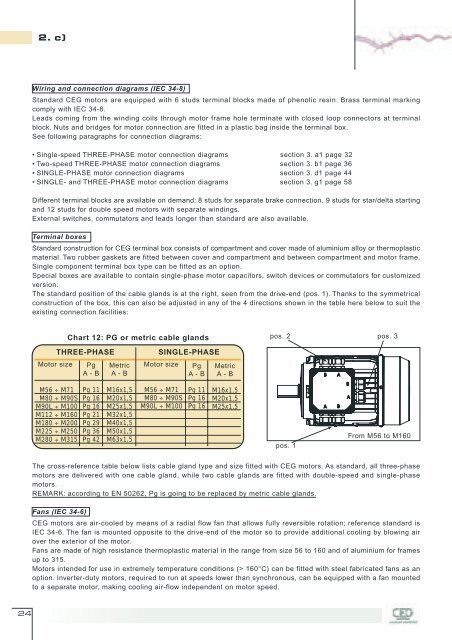
The standard position of the cable glands is at the right, seen from the drive-end (pos. 1). Thanks to the symmetrical<br />
construction of the box, this can also be adjusted in any of the 4 directions shown in the table here below to suit the<br />
existing connection facilities:<br />
M56 ÷ M71<br />
M80 ÷ M90S<br />
M90L ÷ M100<br />
M112 ÷ M160<br />
M180 ÷ M200<br />
M225 ÷ M250<br />
M280 ÷ M315<br />
Chart 12: PG or metric cable glands pos. 2 pos. 3<br />
THREE-PHASE<br />
Motor size Pg Metric<br />
A - B A - B<br />
Pg 11<br />
Pg 16<br />
Pg 16<br />
Pg 21<br />
Pg 29<br />
Pg 36<br />
Pg 42<br />
M16x1,5<br />
M20x1,5<br />
M25x1,5<br />
M32x1,5<br />
M40x1,5<br />
M50x1,5<br />
M63x1,5<br />
SINGLE-PHASE<br />
Motor size<br />
M56 ÷ M71<br />
M80 ÷ M90S<br />
M90L ÷ M100<br />
Pg<br />
A - B<br />
Pg 11<br />
Pg 16<br />
Pg 16<br />
Metric<br />
A - B<br />
M16x1,5<br />
M20x1,5<br />
M25x1,5<br />
pos. 1<br />
From M56 to M160<br />
The cross-reference table below lists cable gland type and size fitted with CEG motors. As standard, all three-phase<br />
motors are delivered with one cable gland, while two cable glands are fitted with double-speed and single-phase<br />
motors.<br />
REMARK: according to EN 50262, Pg is going to be replaced by metric cable glands.<br />
Fans (IEC 34-6)<br />
CEG motors are air-cooled by means of a radial flow fan that allows fully reversible rotation; reference standard is<br />
IEC 34-6. The fan is mounted opposite to the drive-end of the motor so to provide additional cooling by blowing air<br />
over the exterior of the motor.<br />
Fans are made of high resistance thermoplastic material in the range from size 56 to 160 and of aluminium for frames<br />
up to 315.<br />
Motors intended for use in extremely temperature conditions (> 160°C) can be fitted with steel fabricated fans as an<br />
option. Inverter-duty motors, required to run at speeds lower than synchronous, can be equipped with a fan mounted<br />
to a separate motor, making cooling air-flow independent on motor speed.