

KSL-286 | Installation Instructions for Mat Control Box
- No tags were found...

Create successful ePaper yourself
Turn your PDF publications into a flip-book with our unique Google optimized e-Paper software.
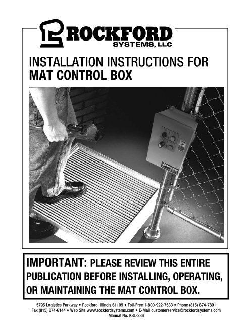
INSTALLATION INSTRUCTIONS FOR<br />
MAT CONTROL BOX<br />
IMPORTANT: PLEASE REVIEW THIS ENTIRE<br />
PUBLICATION BEFORE INSTALLING, OPERATING,<br />
OR MAINTAINING THE MAT CONTROL BOX.<br />
5795 Logistics Parkway • Rock<strong>for</strong>d, Illinois 61109 • Toll-Free 1-800-922-7533 • Phone (815) 874-7891<br />
Fax (815) 874-6144 • Web Site www.rock<strong>for</strong>dsystems.com • E-Mail customerservice@rock<strong>for</strong>dsystems.com<br />
Manual No. <strong>KSL</strong>-<strong>286</strong>
TABLE OF CONTENTS<br />
Safety Map <strong>Control</strong><br />
SECTION 1 - IN GENERAL........................................................................................ 2 - 7<br />
SECTION 2 - CONTROL BOX ......................................................................................... 8<br />
SECTION 2 - INSTALLATION .................................................................................. 9-10<br />
SECTION 4 - TROUBLESHOOTING .............................................................................. 11<br />
SECTION 5 - ORDER FORM & RMA Form................................................................... 12<br />
SECTION 1—IN GENERAL<br />
Safety Map <strong>Control</strong><br />
Safety Precautions<br />
DANGER<br />
DANGER indicates an imminently hazardous situation which, if not avoided, will<br />
result in death or serious injury.<br />
This safety alert symbol identifies important safety messages in this manual. When<br />
you see this symbol, be alert to the possibility of personal injury, and carefully read<br />
the message that follows.<br />
CAUTION<br />
CAUTION used without the safety alert symbol indicates a potentially hazardous situation<br />
which, if not avoided, may result in property damage.<br />
Efficient and safe machine operation depends on the development, implementation and en<strong>for</strong>cement of a safety program. This program requires,<br />
among other things, the proper selection of point-of-operation guards and safety devices <strong>for</strong> each particular job or operation, a thorough safety<br />
training program <strong>for</strong> all machine personnel, that includes instruction on the proper operation of the machine, the point-of-operation guards and<br />
safety devices on the machine, and a regularly scheduled inspection and maintenance program.<br />
Rules and procedures covering each aspect of your safety program should be developed and published both in an operator’s safety manual, as<br />
well as in prominent places throughout the plant and on each machine. Some rules or instructions which must be conveyed to your personnel and<br />
incorporated into your program include:<br />
DANGER<br />
DANGER<br />
Never place your hands or any part of your body in this machine.<br />
Never operate this machine without proper eye, face and body protection.<br />
Never operate this machine unless you are fully trained, instructed, and have read the instruction manual.<br />
Never operate this machine if it is not working properly – stop operating and advise your supervisor immediately.<br />
Never use a foot switch to operate this machine unless a point-of-operation guard or device is provided and properly<br />
maintained.<br />
Never operate this machine unless two-hand trip, two-hand control or presence sensing device is installed at the<br />
proper safety distance. Consult your supervisor should you have any questions regarding the proper safety distance.<br />
Never tamper with, rewire or bypass any control or component on this machine.<br />
A company’s safety program must involve everyone in the company, from top management to operators, since only as a group can any operational problems be<br />
identified and resolved. It is everyone’s responsibility to implement and communicate the in<strong>for</strong>mation and material contained in catalogs and instruction manuals to<br />
all persons involved in machine operation. If a language barrier or insufficient education would prevent a person from reading and understanding various literature<br />
available, it should be translated, read or interpreted to the person, with assurance that it is understood.<br />
FOR MAINTENANCE AND INSPECTION ALWAYS REFER TO THE OEM’s (ORIGINAL MACHINE MANUFACTURER’S)<br />
MAINTENANCE MANUAL OR OWNER’S MANUAL. If you do not have an owner’s manual, please contact the<br />
original equipment manufacturer.<br />
© 2019 Rock<strong>for</strong>d Systems, LLC All rights reserved. Not to be reproduced in whole or in part without written permission. Litho in U.S.A.<br />
(Continued on next page.)<br />
Rock<strong>for</strong>d Systems, LLC<br />
Call 1-800-922-7533 2
Safety References<br />
OSH ACT AND FEDERAL REGULATIONS<br />
Since the enclosed equipment can never overcome a mechanical<br />
deficiency, defect or malfunction in the machine itself, OSHA<br />
(Occupational Safety and Health Administration) has established certain<br />
safety regulations that the employers (users) must comply with so that<br />
the machines used in their plants, factories or facilities are thoroughly<br />
inspected and are in first-class operating condition be<strong>for</strong>e any of the<br />
enclosed equipment is installed.<br />
1. U.S. Government—An Act—Public Law 91-596, 91st Congress,<br />
S. 2193, December 29, 1970:<br />
Duties<br />
SEC. 5. (a) Each employer—<br />
(1) shall furnish to each of his employees employment<br />
and a place of employment which are free from recognized<br />
hazards that are causing or are likely to cause death or serious<br />
physical harm to his employees;<br />
(2) shall comply with occupational safety and health standards<br />
promulgated under this Act.<br />
(b) Each employee shall comply with occupational safety and<br />
health standards and all rules, regulations, and orders issued pursuant<br />
to this Act which are applicable to his own actions and conduct.<br />
2. OSHA 29 CFR Sections that an employer (user) must comply<br />
with include:<br />
1910.211 Definitions.<br />
1910.212 General requirements <strong>for</strong> all machines.<br />
1910.217 Mechanical power presses.<br />
1910.219 Mechanical power-transmission apparatus.<br />
3. OSHA 29 CFR 1910.147 The control of hazardous energy<br />
(lockout/tagout).<br />
4. OSHA Publication<br />
“General Industry Safety and Health Regulations Part 1910,” Code<br />
of Federal Regulations, Subpart O<br />
This publication can be obtained by contacting:<br />
U.S. Government Printing Office<br />
P.O. <strong>Box</strong> 979050<br />
St. Louis, MO 63197-9000<br />
(202) 512-1800<br />
SECTION 1—IN GENERAL<br />
ANSI SAFETY STANDARDS FOR MACHINES<br />
Safety <strong>Mat</strong> <strong>Control</strong><br />
The most complete safety standards <strong>for</strong> machine tools are published<br />
in the ANSI (American National Standards Institute) B11 series. The<br />
following is a list of each ANSI B11 Standard available at the printing<br />
of this publication.<br />
B11–2008 General Safety Requirements<br />
B11.1 Mechanical Power Presses<br />
B11.2 Hydraulic Power Presses<br />
B11.3 Power Press Brakes<br />
B11.4 Shears<br />
B11.5 Iron Workers<br />
B11.6 Lathes<br />
B11.7 Cold Headers and Cold Formers<br />
B11.8 Drilling, Milling, and Boring Machines<br />
B11.9 Grinding Machines<br />
B11.10 Metal Sawing Machines<br />
B11.11 Gear and Spline Cutting Machines<br />
B11.12 Roll Forming and Roll Bending Machines<br />
B11.13 Automatic Screw/Bar and Chucking Machines<br />
B11.14 Withdrawn (Now see ANSI B11.18)<br />
B11.15 Pipe, Tube and Shape Bending Machines<br />
B11.16 Metal Powder Compacting Presses<br />
B11.17 Horizontal Hydraulic Extrusion Presses<br />
B11.18 Coil Processing Systems<br />
B11.19 Per<strong>for</strong>mance Criteria <strong>for</strong> Safeguarding<br />
B11.20 Integrated Manufacturing Systems<br />
B11.21 Lasers<br />
B11.22 CNC Turning Machines<br />
B11.23 Machining Centers<br />
B11.24 Transfer Machines<br />
B11.TR1 Ergonomic Guidelines<br />
B11.TR2 Mist <strong>Control</strong> Considerations<br />
B11.TR3 Risk Assessment<br />
B11.TR4 Programmable Electronic Systems (PES/PLC)<br />
B11.TR5 Sound Level Measurement Guidelines<br />
B11.TR7 Risk Assessment<br />
R15.06 Robotic Safeguarding<br />
B15.1 Mechanical Power Transmission Apparatus<br />
B56.5 Guided Industrial Vehicles and Automated Function of<br />
Manned Industrial Vehicles<br />
B65.1 Printing Press Systems<br />
B65.2 Binding and Finishing Systems<br />
B65.5 Stand-Alone Patten Presses<br />
B151.1 Horizontal (Plastic) Injection Molding Machines<br />
B152.1 Hydraulic Die Casting Presses<br />
B154.1 Rivet Setting Machines<br />
B155.1 Packaging Machinery<br />
01.1 Woodworking Machinery<br />
These standards can be purchased by contacting:<br />
ANSI—American National Standards Institute<br />
25 West 43rd Street<br />
New York, New York 10036<br />
Phone: (212) 642-4900<br />
www.ansi.org<br />
(Continued on next page.)<br />
Rock<strong>for</strong>d Systems, LLC<br />
Call 1-800-922-7533 3
SECTION 1—IN GENERAL<br />
Safety <strong>Mat</strong> <strong>Control</strong><br />
NATIONAL SAFETY COUNCIL SAFETY MANUALS<br />
Other good references <strong>for</strong> safety on machine tools are the National<br />
Safety Council’s Safety Manuals. These manuals are written by various<br />
committees including the Power Press, Forging and Fabricating<br />
Executive Committee. Copies of the following publications are available<br />
from their library:<br />
• Power Press Safety Manual - 5th Edition<br />
• Safeguarding Concepts Illustrated - 7th Edition<br />
• Forging Safety Manual<br />
These manuals can be obtained by contacting:<br />
National Safety Council<br />
1121 Spring Lake Drive<br />
Itasca, IL 60143-3201<br />
1-800-621-7615<br />
www.nsc.org<br />
OTHER SAFETY SOURCES<br />
National Institute of Occupational Safety and Health (NIOSH)<br />
4676 Columbia Parkway<br />
Cincinnati, OH 45226<br />
Toll-Free: 1-800-35-NIOSH (1-800-356-4674)<br />
Phone: (513) 533-8328<br />
www.cdc.gov/niosh<br />
OTHER SAFETY SOURCES (continued)<br />
Robotic Industries Association (RIA)<br />
900 Victors Way, Suite 140<br />
P.O. <strong>Box</strong> 3724<br />
Ann Arbor, MI 48106<br />
Phone: (734) 994-6088<br />
www.roboticsonline.com<br />
NEMA (National Electrical Manufacturers Association)<br />
1300 North 17th Street, Suite 1847<br />
Rosslyn, VA 22209<br />
Phone: (703) 841-3200<br />
www.nema.org<br />
NFPA (National Fire Protection Association)<br />
1 Batterymarch Park<br />
Quincy, MA 02269-9101<br />
Phone: (617) 770-3000<br />
www.nfpa.org<br />
For additional safety in<strong>for</strong>mation and assistance in devising,<br />
implementing or revising your safety program, please contact the<br />
machine manufacturer, your state and local safety councils, insurance<br />
carriers, national trade associations and your state’s occupational<br />
safety and health administration.<br />
Warranty, Disclaimer and Limitation of Liability<br />
WARRANTY<br />
Rock<strong>for</strong>d Systems, LLC warrants that this product will be free from defects in material and workmanship <strong>for</strong> a period of 12 months from the date of shipment<br />
thereof. ROCKFORD SYSTEMS LLC’S OBLIGATION UNDER THIS WARRANTY IS EXPRESSLY AND EXCLUSIVELY LIMITED to repairing or replacing such products<br />
which are returned to it within the warranty period with shipping charges prepaid and which will be disclosed as defective upon examination by Rock<strong>for</strong>d<br />
Systems, LLC This warranty will not apply to any product which will have been subject to misuse, negligence, accident, restriction and use not in accordance<br />
with Rock<strong>for</strong>d Systems, LLC’s instructions or which will have been altered or repaired by persons other than the authorized agent or employees of Rock<strong>for</strong>d<br />
Systems, LLC Rock<strong>for</strong>d Systems, LLC’s warranties as to any component part is expressly limited to that of the manufacturer of the component part.<br />
DISCLAIMER<br />
The <strong>for</strong>egoing Warranty is made in lieu of all other warranties, expressed or<br />
implied, and of all other liabilities and obligations on the part of Rock<strong>for</strong>d<br />
Systems, LLC, including any liability <strong>for</strong> negligence, strict liability, or<br />
otherwise, and any implied warranty of merchantability or fitness <strong>for</strong> a<br />
particular purpose is expressly disclaimed.<br />
LIMITATION OF LIABILITY<br />
Under no circumstances, including any claim of negligence, strict liability, or otherwise,<br />
shall Rock<strong>for</strong>d Systems, LLC be liable <strong>for</strong> any incidental or consequential damages, or<br />
any loss or damage resulting from a defect in the product of Rock<strong>for</strong>d Systems, LLC<br />
(Continued on next page.)<br />
Rock<strong>for</strong>d Systems, LLC<br />
Call 1-800-922-7533 4
SECTION 1—IN GENERAL<br />
Safety <strong>Mat</strong> <strong>Control</strong><br />
Operator Safety Precautions Signs<br />
Accompanying this equipment are 8 1 ⁄2” x 11”<br />
operator safety precautions signs, Part Nos.<br />
KSC-000 and KSC-048, <strong>for</strong> anyone operating<br />
the machine where this equipment will be<br />
installed. These precautions signs are to be<br />
given to all operators, including setup people,<br />
maintenance personnel and supervisors.<br />
KSC-000 Front<br />
These signs should also be attached to the<br />
machine, readily accessible and visible to<br />
the operator. (A hole in the corner of these<br />
signs is provided <strong>for</strong> attaching purposes.)<br />
Additional copies of these precautions are<br />
available. Please call, write, fax, or use the<br />
order <strong>for</strong>m found on a later page in this<br />
manual.<br />
KSC-048 Front<br />
When a language barrier or insufficient<br />
education prevents a person from reading or<br />
understanding the contents of these operator<br />
safety precautions signs, you should either<br />
translate this in<strong>for</strong>mation or have it read or<br />
interpreted to the person. Make sure that<br />
the person understands the in<strong>for</strong>mation. To<br />
order these signs in Spanish, use Part No.<br />
KSC-000S or Part No. KSC-048S; in French,<br />
use Part No. KSC-000F or Part No. KSC-048F.<br />
These precautions must be reviewed daily.<br />
Safety Precautions On Reverse Side<br />
(Continued on next page.)<br />
Rock<strong>for</strong>d Systems, LLC<br />
Call 1-800-922-7533 5
SECTION 1—IN GENERAL<br />
Safety <strong>Mat</strong> <strong>Control</strong><br />
Danger Sign to be Mounted on Machine<br />
Accompanying this equipment is a 10” x 12” polyethylene danger sign, Part No. KSC-056. This sign MUST BE<br />
PERMANENTLY MOUNTED IN A PROMINENT LOCATION on the machine where this equipment is installed. This sign<br />
must be in a LOCATION THAT IS EASILY VISIBLE to the operator, setup person, or other personnel who work on<br />
or around this machine. ALWAYS mount this sign with bolts or rivets when installing the enclosed equipment.<br />
If any danger sign becomes destroyed or unreadable, the sign must be replaced immediately. Contact factory <strong>for</strong> replacement danger sign(s).<br />
Never operate this machine unless the danger sign(s) is in place.<br />
Operator Safety<br />
Precautions Sign<br />
Part No. KSC-056 Danger Sign—English<br />
Part No. KSC-056S Danger Sign—Spanish<br />
Part No. KSC-056F Danger Sign—French<br />
This control box and mat configuration are not intended <strong>for</strong> use without<br />
point-of-operation safeguarding. A mat is auxiliary safeguarding only.<br />
“Mechanical Power Press Safety” Booklet<br />
A copy of Booklet No. MPPS (Mechanical Power Press Safety) is available upon request. This booklet is copied verbatim from the CFR (Code of<br />
Federal Regulations) and contains all relevant sections of the OSHA standards concerning power presses with which an employer (user) must<br />
comply. The enclosed equipment must be installed, used and maintained to meet these standards. Specifically, any time a foot switch is used, a<br />
suitable point-of-operation safeguard or device must be used to prevent bodily injury. In addition, every press must be provided with a<br />
point-of-operation safeguard! Please review this booklet be<strong>for</strong>e installing the enclosed equipment. If you are unfamiliar with these detailed safety<br />
regulations, which include regulations on safeguarding the point of operation properly, you may want to attend our regularly scheduled machine<br />
safeguarding seminars. To obtain detailed in<strong>for</strong>mation about these training seminars, please call, fax, write, or check our Web site. Our telephone,<br />
fax number, Web site, and mailing address are on the front cover of this manual.<br />
(Continued on next page.)<br />
Rock<strong>for</strong>d Systems, LLC<br />
Call 1-800-922-7533 6
General Description of Components in the System<br />
The mat control box system includes the following items.<br />
SECTION 1—IN GENERAL<br />
Safety <strong>Mat</strong> <strong>Control</strong><br />
1. <strong>Installation</strong> manual, danger signs, and electrical control schematics<br />
2. Safety mat control box<br />
Individual packages may vary in contents. However, a packing list is always enclosed showing exactly what material was shipped on this order.<br />
Please check the components actually received against this packing list immediately.<br />
Safety <strong>Mat</strong>s<br />
Safety mats may have been included with your order. The mat consists of an electrical switch that is completely sealed inside of a molded vinyl mat.<br />
It is waterproof, highly resistant to wear, oils, grease, and most common chemicals. The surface of the mat is a slip-resistant corrugated material and<br />
the built-in switch is sensitive to foot pressure (3 lbs), yet durable enough to withstand the harsh industrial environment. Some mats are designed<br />
to accommodate aluminum hold-down ramp edging; others have a molded ramp edge.<br />
These types of mats are constructed <strong>for</strong> machines where operator safety is required. The mat has four wires. When they are connected to the mat<br />
control (see page 9 and the enclosed drawing), the control relay deenergizes when the mat leads are either shorted or broken open.<br />
NOTE: In the mat control box, one side of the mat control box must be connected between terminals 103 and 105; the other side of the mat contact<br />
must be connected between terminals 104 and 106. See the connection diagram on page 9 and the enclosed drawing.<br />
To install a safety mat, lay the mat in position on the floor where protection is required. Some mats have an aluminum ramp edging that can secure<br />
the mat to the floor. Depending of the area that the mats will cover, other edging and multiple mats may be furnished.<br />
Preliminary Steps Be<strong>for</strong>e <strong>Installation</strong><br />
Be<strong>for</strong>e proceeding with the installation of the enclosed equipment, you should undertake the following preliminary steps.<br />
1. Read and make sure you understand this entire instruction manual.<br />
2. Refer to the front cover, other line drawings and photos, then make a sketch of your installation to plan the location of the enclosed equipment<br />
on the machine.<br />
3. Please make sure the machine is in first-class condition. Be<strong>for</strong>e starting any installation, it is essential that the machine is thoroughly<br />
inspected. Be sure all mechanical components and all collateral equipment are in first-class operating condition. Your inspection should be<br />
done according to the machine manufacturer’s installation and maintenance instruction manual. If you have any doubts or questions concerning<br />
the condition of the machine, contact the machine manufacturer <strong>for</strong> assistance. Repair or replace all parts not operating properly be<strong>for</strong>e<br />
proceeding.<br />
Inspection and maintenance programs must be established and implemented to keep machines in first-class condition.<br />
Safety programs must include thorough inspections of each machine on a weekly basis and records kept of these<br />
inspections. Any part of the machine that is worn, damaged or is not operating properly must be replaced immediately or<br />
repaired be<strong>for</strong>e the machine is used.<br />
4. Verify that the machine is in first-class condition and operating properly; shut off all power to the machine. Padlock all electrical and pneumatic<br />
energy in the off position and do not actuate the machine again until the installation of all package components has been completed. Lockout/<br />
tagout energy isolation procedures must always be practiced and en<strong>for</strong>ced.<br />
(Continued on next page.)<br />
Rock<strong>for</strong>d Systems, LLC<br />
Call 1-800-922-7533 7
SECTION 2—CONTROL BOX<br />
Safety <strong>Mat</strong> <strong>Control</strong><br />
<strong>Control</strong> <strong>Box</strong><br />
This mat control box provides an interface between the safety mats and the existing<br />
machine control. The mat control is furnished in a dust- and oil-tight enclosure. It<br />
includes a mat control relay, two <strong>for</strong>ce-guided relays, a mat reset push button, a<br />
maintenance off/on selector switch, a red indicator light, and a green indicator light.<br />
The mat control will require a reset when the control box is first turned on. As long<br />
as the mat is clear when the reset button is pushed, the machine will be allowed to<br />
start—the green light will be on, thus indicating mat active. If the mat is stepped on,<br />
the green light will go off and the reset button must be pushed to allow the machine<br />
to restart.<br />
A maintenance off/on selector switch is furnished <strong>for</strong> use during maintenance of the<br />
machine. When the maintenance mode is set to on, the red light will illuminate—thus<br />
indicating maintenance mode on. This will allow the machine to run even if the mat is<br />
stepped on during maintenance. When the maintenance mode is set to off, the control<br />
will function as described above.<br />
Outside View of <strong>Control</strong> <strong>Box</strong><br />
Mount the control box in an accessible and readily visible location, either on or near the<br />
machine where the mats are to be located. Although operation of this control will not<br />
be adversely affected by normal machine operation, excessive shock or vibration may<br />
require shock mounting in specific applications.<br />
SPECIFICATIONS<br />
Part Number.........................................................................................RKR-162<br />
Enclosure................................................................ NEMA 12—12” x 10” x 8”<br />
Voltage........................................................................................ 120V AC 60Hz<br />
Machine Enable Circuit..........................................2 Sets of 2 NO Contacts @<br />
10A 120V AC<br />
Inside View of <strong>Control</strong> <strong>Box</strong><br />
1 MR & 2 MR<br />
Indicator Lights and<br />
Selector Switch<br />
<strong>Mat</strong> <strong>Control</strong><br />
(Continued on next page.)<br />
Rock<strong>for</strong>d Systems, LLC<br />
Call 1-800-922-7533 8
<strong>Installation</strong> Considerations<br />
Wiring<br />
SECTION 3—INSTALLATION<br />
Safety <strong>Mat</strong> <strong>Control</strong><br />
We recommend that National Electrical Code practices be followed <strong>for</strong> wiring, especially color coding and the use of numbered wire markers on<br />
both ends of every wire. Color coding is black <strong>for</strong> power circuits, red <strong>for</strong> 120V AC control circuits, white <strong>for</strong> current carrying ground (frequently<br />
referred to as the right hand common), and green <strong>for</strong> any equipment grounding conductor.<br />
Do not use solid wire.<br />
Input Connections<br />
Connect 120V AC three-wire service to the mat control box. Ground should be connected to the panel with the furnished ground screw. Connect<br />
the hot side (black) of the 120V AC to terminal 1. Connect the common (white) to terminal 2. If the 120V AC is not available on the machine, then<br />
a trans<strong>for</strong>mer must be incorporated to step down the line voltage. This trans<strong>for</strong>mer must be rated in accordance with the control load requirement.<br />
On most installations, the incoming power <strong>for</strong> the mat control is interfaced with the motor-starter circuit so that power is only applied to the mat<br />
control box when the drive motor is running. This does not apply to machine applications where the emergency-stop circuit is ahead or upstream<br />
of the motor-starter circuit.<br />
<strong>Mat</strong> Connections<br />
Connect the leads from one side of the mat to terminals 103 and 105. Connect the leads from the other side of the mat to terminals 104 and 106.<br />
See diagram below and refer to the enclosed RKR-162 drawing.<br />
Connection Diagram<br />
1 2<br />
103 104 105 106 200 201<br />
202 203<br />
GND B W<br />
120V 60 Hz<br />
Safety <strong>Mat</strong><br />
Machine Enable Circuit<br />
Output Connections<br />
The output relays (mat relays 1 & 2) are wired to the terminal. With power applied and the mat clear, circuits 200-201 and provide 2 NO contacts<br />
in series to be tied in to the machine enable circuit.<br />
(Continued on next page.)<br />
Rock<strong>for</strong>d Systems, LLC<br />
Call 1-800-922-7533 9
SECTION 3—INSTALLATION<br />
Safety <strong>Mat</strong> <strong>Control</strong><br />
Initial Checkout Procedure<br />
Be<strong>for</strong>e per<strong>for</strong>ming the initial checkout procedure, make certain all power is disconnected from the machine<br />
to be controlled. Always disconnect power to the machine control elements be<strong>for</strong>e opening the safety mat<br />
control box.<br />
If multiple mats are connected to the safety mat control, run this procedure individually <strong>for</strong> each mat.<br />
1. Remove power to the machine control elements.<br />
2. Apply <strong>for</strong>ce to the mat’s sensing area.<br />
3. Apply input power to the mat control relay at terminals A1 and A2, or B1 and B2. Verify that only the power indicator LED is on.<br />
4. Clear the mat sensing area.<br />
5. Manual Rest Mode: Ch1 and Ch2 indicators should be flashing. Manually reset the mat control.<br />
6. Verify that Ch1 and Ch2 indicators both come on. If only one indicator comes on or if any indicator is flashing, refer to the troubleshooting section<br />
on the next page <strong>for</strong> more in<strong>for</strong>mation. Return to step 2 after correcting the problem.<br />
7. Apply <strong>for</strong>ce in several locations to the mat’s sensing area. Verify that the Ch1 and Ch2 indicators turn off simultaneously. If either indicator<br />
does not go off, disconnect the input power and check all wiring. Return to step 2 after correcting the problem.<br />
8. Repeat <strong>for</strong> each safety mat individually if more than one mat is connected.<br />
9. Close and secure the safety mat control box. Apply power to the machine control elements and per<strong>for</strong>m the periodic checkout procedure below.<br />
Periodic Checkout Procedure<br />
If multiple mats are connected to the safety mat control, run this procedure individually <strong>for</strong> each mat.<br />
1. With the machine running, apply <strong>for</strong>ce to the mat’s sensing area. Verify that the machine stops within the expected time period.<br />
2. Remove <strong>for</strong>ce from the safety mat. Verify that the machine does not restart.<br />
3. Manually reset the mat control. Verify that the machine cycle can be restarted by normal initiation.<br />
4. Repeat <strong>for</strong> each safety mat individually if more than one mat is connected.<br />
(Continued on next page.)<br />
Rock<strong>for</strong>d Systems, LLC<br />
Call 1-800-922-7533 10
Troubleshooting<br />
SECTION 4—TROUBLESHOOTING<br />
Safety <strong>Mat</strong> <strong>Control</strong><br />
All troubleshooting, as well as installation, must be per<strong>for</strong>med by qualified and properly trained personnel.<br />
Furthermore, when a defective component is found, do not operate the machine until that component has been<br />
replaced with an exact replacement part.<br />
Condition Indicator Status Possible Causes or Solution<br />
Module will not reset<br />
No fault indicated<br />
No fault indicated<br />
No fault indicated<br />
Fault<br />
1 MR & 2 MR do not<br />
energize<br />
Power LED ON<br />
Fault LED OFF<br />
Ch 1 LED Flashing<br />
Ch 2 LED Flashing<br />
Power LED ON<br />
Fault LED OFF<br />
Ch 1 LED OFF<br />
Ch 2 LED OFF<br />
Power LED ON<br />
Fault LED OFF<br />
Ch 1 LED Flashing<br />
Ch 2 LED Flashing<br />
Power LED ON<br />
Fault LED OFF<br />
Ch 1 LED Flashing<br />
Ch 2 LED Flashing<br />
Power LED ON<br />
Fault LED ON<br />
Ch 1 LED ON<br />
Ch 2 LED ON<br />
All LEDs OFF<br />
Dim LEDs<br />
Fault LED Flickers<br />
Power LED ON<br />
Fault LED OFF<br />
Ch 1 LED ON<br />
Ch 2 LED ON<br />
Waiting <strong>for</strong> manual reset:<br />
• EDM monitoring contacts are not closed. Check 1 MR & 2 MR.<br />
• Check jumper at S32-S35 (auto reset) or S32-S33 (manual reset).<br />
• Check reset button connection.<br />
Safety mat appears actuated:<br />
• Check mat <strong>for</strong> damage or heavy debris.<br />
• Check <strong>for</strong> proper wiring.<br />
• Check <strong>for</strong> short in the wiring.<br />
Channel 1 open:<br />
• Check wiring to S11-S12.<br />
• Check connectors are properly seated.<br />
Channel 2 open:<br />
• Check wiring to S21-S22.<br />
• Check connectors are properly seated.<br />
Possible temporary fault:<br />
• Check <strong>for</strong> loose wiring.<br />
• Actuate the mat to clear the fault.<br />
Possible internal fault:<br />
• Return to factory <strong>for</strong> repair or replacement.<br />
Possible fault in the machine control or wiring to the module:<br />
• Check input power connections or external fuses.<br />
• Check connectors are properly seated.<br />
Power LED dim:<br />
• Check power supply capacity and load.<br />
Other LEDs dim:<br />
• May glow during power-up (normal).<br />
• Check power supply load and capacity.<br />
This is normal while the Fault LED is ON.<br />
Possible fault in machine control or an open circuit between machine control and<br />
mat relays:<br />
• Check continuity of safety outputs (e.g. between terminals 13 & 14).<br />
• Check control wires and connectors.<br />
• Check mat relays.<br />
(Continued on next page.)<br />
Rock<strong>for</strong>d Systems, LLC<br />
Call 1-800-922-7533 11
SECTION 5—ORDER FORM FOR SIGNS & LITERATURE—RMA FORM<br />
Safety <strong>Mat</strong> <strong>Control</strong><br />
ORDER FORM FOR SIGNS AND LITERATURE<br />
This instruction manual references signs and literature available <strong>for</strong> your machines. This order <strong>for</strong>m is <strong>for</strong> your convenience to order additional signs<br />
and/or literature as needed. (This order <strong>for</strong>m is part of your installation manual so please make a copy of it when ordering.)<br />
Company<br />
Address<br />
City State Zip<br />
Phone<br />
Fax<br />
Name Purchase Order No. Date<br />
Part No. Description Quantity Required<br />
<strong>KSL</strong>-<strong>286</strong><br />
Instruction Manual—<strong>Mat</strong> <strong>Control</strong> <strong>Box</strong><br />
KSC-000<br />
KSC-000S<br />
KSC-000F<br />
KSC-000<br />
KSC-000S<br />
KSC-000F<br />
KSC-056<br />
KSC-056S<br />
KSC-056F<br />
<strong>KSL</strong>-051<br />
Operator Safety Precautions Sign—Metal<strong>for</strong>ming (English)<br />
Operator Safety Precautions Sign—Metal<strong>for</strong>ming (Spanish)<br />
Operator Safety Precautions Sign—Metal<strong>for</strong>ming (French)<br />
Operator Safety Precautions Sign—Metal-Cutting (English)<br />
Operator Safety Precautions Sign—Metal-Cutting (Spanish)<br />
Operator Safety Precautions Sign—Metal-Cutting (French)<br />
Danger Sign (General Machine) 10” x 12” (English)<br />
Danger Sign (General Machine) 10” x 12” (Spanish)<br />
Danger Sign (General Machine) 10” x 12” (French)<br />
Mechanical Power Press Safety Booklet<br />
For prices and delivery, please use address, phone or fax number listed on the front cover of this manual.<br />
Your Signature<br />
Date<br />
RETURN MATERIALS AUTHORIZATION REQUEST FORM<br />
To return material <strong>for</strong> any reason contact the sales department in our organization at 1-800-922-7533 <strong>for</strong> an RMA Number. All return materials<br />
shipments must be prepaid. Complete this <strong>for</strong>m and send with material to 5795 Logistics Parkway, Rock<strong>for</strong>d, IL 61109. Make sure the RMA<br />
Number is plainly identified on the outside of the shipping container.<br />
Company<br />
Address<br />
City State Zip<br />
Phone<br />
Contact Name<br />
Fax<br />
Representative<br />
Items Authorized To Return on RMA No. Original Invoice No. Date<br />
Part No. Serial No. Description<br />
Service Requested: Full Credit 25% Restocking Repair & Return Warranty Replacement<br />
Reason <strong>for</strong> return (describe in detail):<br />
Return <strong>Mat</strong>erials Authorized By<br />
Date<br />
<strong>KSL</strong>-<strong>286</strong>/0619


