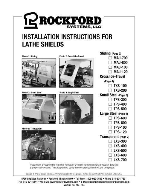
KSL-244 | Installation Instructions for Lathe Shields
You also want an ePaper? Increase the reach of your titles
YUMPU automatically turns print PDFs into web optimized ePapers that Google loves.
INSTALLATION INSTRUCTIONS FOR<br />
LATHE SHIELDS<br />
Photo 1: Sliding<br />
Photo 3: Small Steel<br />
Photo 5: Transparent<br />
Photo 2: Crosslide-Travel<br />
Photo 4: Large Steel<br />
Sliding (Page 2)<br />
n MAJ-700<br />
n MAJ-800<br />
n MAJ-100<br />
n MAJ-120<br />
Crosslide-Travel<br />
(Page 4)<br />
n TXS-100<br />
n TXS-200<br />
Small Steel (Page 5)<br />
n TPS-300<br />
n TPS-400<br />
n TPS-500<br />
Large Steel (Page 6)<br />
n TPS-600<br />
n TPS-800<br />
n TPS-100<br />
n TPS-120<br />
Transparent (Page 7)<br />
n LXS-300<br />
n LXS-400<br />
n LXS-500<br />
n LXS-600<br />
n LXS-700<br />
These shields are designed <strong>for</strong> machines that require protection from chips (swarf) and coolant generated<br />
at the point of operation. They also provide a barrier between the machine chuck and the operator.<br />
Copyright © 2019 by Rock<strong>for</strong>d Systems, LLC All rights reserved. Not to be reproduced in whole or in part without written permission. Litho in U.S.A.<br />
5795 Logistics Parkway • Rock<strong>for</strong>d, Illinois 61109 • Toll-Free 1-800-922-7533 • Phone 815-874-7891<br />
Fax 815-874-6144 • Web Site www.rock<strong>for</strong>dsystems.com • E-Mail customerservice@rock<strong>for</strong>dsystems.com<br />
Manual No. <strong>KSL</strong>-<strong>244</strong>
SECTION 1 —SLIDING<br />
<strong>Lathe</strong> Shield <strong>Installation</strong> Manual<br />
Introduction<br />
Figure 1.2<br />
Setscrews<br />
These shields are designed <strong>for</strong> lathes with chucks up to 48 inches.<br />
The ball-bearing carriage securely mounts to the headstock by four<br />
flanged mounting posts, as illustrated. The four mounting brackets<br />
are adjustable to provide easy mounting to the headstock. The<br />
mounting posts can be attached without interfering with any part of the<br />
equipment housed within the headstock.<br />
Cut Off<br />
to Suit<br />
Cast Boss Can<br />
Be Rotated<br />
The sliding shields slide out of the way over the headstock, allowing<br />
the operator access to the point of operation <strong>for</strong> loading and unloading<br />
workpieces, changing tooling, changing chucks, removing swarf, etc.<br />
Cast Boss<br />
DIMENSION CHART<br />
Part No. A B Chuck Diameter<br />
MAJ-700 26” 21” 28”<br />
MAJ-800 27-1/4” 23” 32”<br />
MAJ-100 29-1/2” 27” 40”<br />
MAJ-120 33-1/4” 30-3/4” 48”<br />
Smooth-Action<br />
Sliding Chassis<br />
Mounting<br />
Posts<br />
Cross-member<br />
This drawing illustrates how easily the four mounting posts<br />
attach to the headstock of the lathe. It also shows how the<br />
sliding shield mounts to the rails of the ball-bearing carriage.<br />
Frame<br />
Figure 1.1<br />
Dimensions<br />
12” Max.<br />
Can Be Cut to Length<br />
Figure 1.3<br />
Adj. From<br />
2” to 12”<br />
A<br />
15 3 ⁄4”<br />
Centers<br />
B<br />
Smooth-Action<br />
Sliding Chassis<br />
20”<br />
<strong>Installation</strong><br />
1. Remove all packing material from the shield and its mounting assembly.<br />
2. Select the mounting location of the shield by measuring the distance<br />
from the headstock of the lathe to the point the shield must travel.<br />
Make sure the underside of the shield clears the chuck. Cut<br />
the mounting posts to length, if required.<br />
3. Drill and tap holes <strong>for</strong> the mounting posts. Make sure the holes do<br />
not interfere with gears, shafts, etc., and the assembly is located<br />
so it allows the shield to slide back far enough to expose the chuck.<br />
4. The posts can be attached anywhere along the length of the<br />
crossmembers. They also can be mounted to the right or left by<br />
sliding or rotating the cast bosses. The cast bosses clamp to the<br />
crossmember and mounting posts (see Figure 1.2).<br />
5. Bolt the four mounting posts to the headstock. (Bolts not furnished.)<br />
6. Position the frame onto the posts.<br />
7. With the frame positioned on the posts, attach the shield to the<br />
frame using the six socket setscrews provided (see Figure 1.2).<br />
Make sure access to the machine controls is not blocked.<br />
REPLACEMENT WINDOW<br />
Part No.<br />
MAW001<br />
MAW-002<br />
MAW-003<br />
MAW-004<br />
Replacement Polycarbonate Window For:<br />
MAJ-700<br />
MAJ-800<br />
MAJ-100<br />
MAJ-120<br />
When installing, allow enough clearance to ensure<br />
the shield or any of its parts will not be hit by normal<br />
movements of the chuck, crosslide, workpiece, etc.<br />
Rock<strong>for</strong>d Systems, LLC<br />
2 Call: 1-800-922-7533
SECTION 2 —MOUNTING BRACKETS<br />
<strong>Lathe</strong> Shield <strong>Installation</strong> Manual<br />
Introduction<br />
Mounting brackets are supplied separately <strong>for</strong> any of the shields found<br />
on pages 5-7. These brackets mount to the headstock of the lathe.<br />
Fasteners are not furnished. The transparent and small steel shields<br />
are attached to a zinc-plated extension tube which fits into these<br />
mounting brackets.<br />
There are two principal types of mounting brackets available. Type A<br />
(Figure 2.1) is used <strong>for</strong> mounting to the top or the side of the headstock.<br />
Type B (Figure 2.2) is used <strong>for</strong> mounting to the face of the headstock.<br />
For difficult mounting conditions, the Type A1 bracket (Figure 2.3) may<br />
be used. This bracket incorporates a telescopic height adjustment and<br />
can be swivelled up to an angle of 90° as required.<br />
Figure 2.1<br />
Type A Bracket<br />
Part No. LXS-650<br />
For mounting to the top or<br />
side of the headstock.<br />
Figure 2.2<br />
Type B Bracket<br />
Part No. LXS-652<br />
<strong>for</strong> mounting to the face of the headstock.<br />
2 27 ⁄32”<br />
1 1 ⁄2”<br />
2”<br />
1<br />
⁄2”<br />
1 1 ⁄2”<br />
2 Holes .28” Dia.<br />
1”<br />
Bore<br />
1”<br />
Bore<br />
1”<br />
1 1 ⁄2” Dia.<br />
Figure 2.3<br />
Type A1 Bracket<br />
Part No. LXS-651<br />
<strong>for</strong> extended mounting to the<br />
top or side of the headstock.<br />
1” Bore<br />
1 5 ⁄16”<br />
Extends From 3 1 ⁄2”<br />
to 5”<br />
Shown Extended<br />
3”<br />
2 Holes .32” Dia.<br />
1 1 ⁄4”<br />
90° Movement of Center Piece<br />
if Required<br />
2 21 ⁄64”<br />
1 1 ⁄2”<br />
2”<br />
2 3 ⁄8”<br />
2 Holes .32” Dia.<br />
(Continued on next page.)<br />
Rock<strong>for</strong>d Systems, LLC<br />
Call: 1-800-922-7533 3<br />
3”
SECTION 2 —MOUNTING BRACKET<br />
<strong>Lathe</strong> Shield <strong>Installation</strong> Manual<br />
Introduction (continued)<br />
Figure 2.4<br />
Type B2 Bracket<br />
Part No. LXS-653<br />
<strong>for</strong> mounting to the face of the headstock<br />
when two different sized shields are used.<br />
The Type B2 bracket (Figures 2.4 and 2.5) has a two-socket mounting.<br />
It can be fastened to the face of the headstock where shields with<br />
different diameters are used. It accommodates 3-jaw and 4-jaw<br />
chucks. The inner socket is used <strong>for</strong> the 3-jaw, smaller chuck shield.<br />
When changing over to a larger, 4-jaw chuck, the shield is removed<br />
from the inner socket and replaced by a larger diameter shield inserted<br />
into the outer socket. This accommodates the 4-jaw chuck.<br />
Full dimensions, showing the shield in relation to the chuck, are<br />
illustrated in Figure 6.2 on page 8.<br />
Figure 2.5<br />
3-Jaw Chuck<br />
1<br />
⁄2”<br />
7 1 ⁄2”<br />
3”<br />
2”<br />
1<br />
⁄2” 2 3 ⁄8” 3 3 ⁄4”<br />
1<br />
⁄2”<br />
1 3 ⁄4”<br />
4-Jaw<br />
Chuck<br />
The electrical interlocking bracket assembly (Figure 2.6) includes the Type B bracket <strong>for</strong> mounting to the face of the headstock. This bracket<br />
assembly has an interlock switch that can be interlocked to the lathe’s motor starter circuit. In most cases, the normally open contact of the switch<br />
is used. The cam is then positioned on the mounting rod of the shield so it pushes the wheel of the switch and holds the contact closed while the<br />
shield is down in position. When the shield is lifted up, the contact of the switch is opened, which causes the machine to stop.<br />
Figure 2.6<br />
Part No. FKT-781<br />
Interlocking Bracket Assembly<br />
Interlock Switch Specifications<br />
Contacts..................................................................2 NO and 2 NC<br />
Actuating Directions........................................................................... 4<br />
Switching Ability........................ 3 A @ 230 V AC, 0.27 A @ 230 V DC<br />
Conduit Adapter...................................................................M20 to 1 ⁄2”<br />
Operating Temperature............................................. -13° to 176°F<br />
............................................................................... (-25° to 80°C)<br />
Rock<strong>for</strong>d Systems, LLC<br />
4 Call: 1-800-922-7533
SECTION 3 —CROSSLIDE-TRAVEL<br />
<strong>Lathe</strong> Shield <strong>Installation</strong> Manual<br />
Introduction<br />
These lathe shields mount and travel with the crosslide <strong>for</strong> protection<br />
when machining long workpieces. The steel structure provides<br />
protection from flying chips and coolant. The window permits visibility<br />
into the point of operation. The front portion of the shield hinges up <strong>for</strong><br />
access. This shield is ideal <strong>for</strong> lathes with long beds. Special sizes are<br />
available on request.<br />
<strong>Installation</strong><br />
1. Remove all packing material from the shield and its mounting assembly.<br />
2. Select the mounting bracket location on the crosslide of the<br />
machine and spot holes. Make sure the holes do not interfere with<br />
gears, shafts, etc. (A mounting bracket is not part of the assembly.<br />
It must be ordered separately—see pages 3-4 <strong>for</strong> choices.)<br />
3. Drill and tap two holes <strong>for</strong> the mounting bracket. (See pages 3-4 <strong>for</strong><br />
bracket dimensions or use the bracket as a template.)<br />
4. Fasten the mounting bracket to the crosslide of the lathe using<br />
Allen-head fasteners (not furnished).<br />
5. Assemble the shield to the mounting rod with the fasteners<br />
provided. See Figure 3.2.<br />
6. Slide the mounting rod into the mounting bracket and tighten at the<br />
desired height.<br />
DIMENSION CHART<br />
Part No. A B C D E<br />
TXS-100 17” 8” 10” 12” 12”<br />
TXS-200 23” 11” 12” 14-1/2” 13-3/4”<br />
Figure 3.1Dimensions<br />
A<br />
8 1 ⁄2”<br />
8 1 ⁄2” D<br />
4”<br />
3<br />
⁄4”<br />
E<br />
REPLACEMENT PARTS<br />
Part No. Description<br />
TXW-000 Replacement Polycaronate Window<br />
TXR-000 Mounting Rod and Support Bar<br />
B C<br />
Hinge<br />
20 1 ⁄4”<br />
When installing, allow enough clearance to ensure<br />
the shield or any of its parts will not be hit by normal<br />
movements of the chuck, crosslide, workpiece, etc.<br />
Figure 3.2<br />
Exploded View<br />
Fastener<br />
Support Bar<br />
Hinges up <strong>for</strong><br />
Access<br />
Washer<br />
Setscrew<br />
Fastener<br />
Mounting<br />
Rod<br />
Allen-Head<br />
Fasteners<br />
(not furnished)<br />
LXS-650 Mounting Bracket<br />
(supplied separately). See pages<br />
3-4 <strong>for</strong> other choices.<br />
Rock<strong>for</strong>d Systems, LLC<br />
Call: 1-800-922-7533 5
SECTION 14—SMALL —SLIDINGSTEEL<br />
<strong>Lathe</strong> Shield <strong>Installation</strong> Manual<br />
Introduction<br />
These small steel chuck shields are fabricated of 18-gauge steel and can be used on smaller lathes that have chucks up to 18 1 ⁄4” in diameter.<br />
Each shield is furnished with a 1” x 13” mounting rod which can be cut to length if required. This mounting rod is fastened to the headstock of the<br />
lathe using a mounting bracket (must be ordered separately—see pages 3-4). The mounting rod is also used to hinge the entire shield. The shield<br />
can be lifted and swung up from the operator <strong>for</strong> quick and easy access to the chuck and the part being machined.<br />
<strong>Installation</strong><br />
1. Remove all packing material from the shield and its mounting assembly.<br />
2. Select the mounting bracket location and spot holes on the<br />
machine. Make sure the holes do not interfere with gears, shafts,<br />
etc. (A mounting bracket is not part of the assembly. It must be<br />
ordered separately—see pages 3-4 <strong>for</strong> choices.)<br />
3. Drill and tap two holes <strong>for</strong> the mounting bracket. (See pages 3-4 <strong>for</strong><br />
bracket dimensions or use the bracket as a template.)<br />
4. Fasten the mounting bracket to the headstock of the lathe using<br />
Allen-head fasteners (not furnished).<br />
5. Slide the shield onto the mounting rod and tighten the setscrews.<br />
See Figure 4.1.<br />
6. Slide the mounting rod into the mounting bracket and tighten the<br />
knob. See Figure 4.1.<br />
Note: Maintenance instructions <strong>for</strong> the polycarbonate window are on page 9.<br />
Figure 4.2 Dimensions<br />
Figure 4.1<br />
Mounting<br />
Bracket<br />
1”<br />
C Max Dia.<br />
A<br />
B<br />
1” Bore<br />
1 3 ⁄8”<br />
Window<br />
Four 1 ⁄4-20<br />
Setscrews<br />
8” 7”<br />
D<br />
13” Rod<br />
DIMENSION CHART<br />
Part No. A B C D<br />
TPS-300 12” 7-1/2” 11” 14-3/4”<br />
TPS-400 15-1/2” 9-1/4” 14-1/2” 6-1/4”<br />
TPS-500 19-1/4” 11-1/2” 18-1/4” 8”<br />
When installing, allow enough clearance to ensure<br />
the shield or any of its parts will not be hit by normal<br />
movements of the chuck, crosslide, workpiece, etc.<br />
REPLACEMET PARTS<br />
Part No. Description<br />
FKT-160 13” Mounting Rod<br />
TPW-003 Replacement Window <strong>for</strong> TPS-300<br />
TPW-004 Replacement Window <strong>for</strong> TPS-400<br />
TPW-005 Replacement Window <strong>for</strong> TPS-500<br />
Rock<strong>for</strong>d Systems, LLC<br />
6 Call: 1-800-922-7533
Introduction<br />
SECTION 5—LARGE STEEL<br />
<strong>Lathe</strong> Shield <strong>Installation</strong> Manual<br />
These large steel chuck shields are double-hinged <strong>for</strong> access to the chuck. The front hinged portion can be swung up <strong>for</strong> workpiece changes and<br />
the entire shield can be hinged back <strong>for</strong> changing chucks. The rear mounting rod hinges the entire shield. This shield is furnished with a mounting<br />
rod, a mounting plate, and a support bar.<br />
<strong>Installation</strong><br />
1. Remove all packing material from the shield and its mounting assembly.<br />
2. Select the mounting bracket location on the machine. Make sure<br />
the holes do not interfere with gears, shafts, etc.<br />
3. Spot and drill holes in the mounting plate; spot, drill and tap holes<br />
in the headstock of the lathe.<br />
4. Fasten the mounting bracket to the headstock of the lathe.<br />
(Fasteners not furnished.)<br />
5. Remove the outside guide bushing from the mounting rod. See<br />
Figure 5.1.<br />
6. Slide the shield onto the mounting rod; return the guide bushing<br />
and tighten the setscrews.<br />
7. Spot, drill and tap holes <strong>for</strong> the support bar. Attach the support<br />
bar to the face of the headstock. When the shield is in its normal<br />
operating position, it rests on the support bar. Due to the variation<br />
in headstock dimensions, a specially fabricated support bar may<br />
be required.<br />
Figure 5.2 Dimensions<br />
13 3 ⁄4”<br />
When installing, allow enough clearance to ensure<br />
the shield or any of its parts will not be hit by normal<br />
movements of the chuck, crosslide, workpiece, etc.<br />
Hinge<br />
A<br />
Support Bar<br />
Mounting Rod and Plate<br />
Figure 5.1<br />
Top View of Shield Hinge Front of <strong>Lathe</strong><br />
Headstock<br />
Part No.<br />
A<br />
TPS-600 24”<br />
TPS-800 32”<br />
TPS-100 40”<br />
TPS-120 47-1/2”<br />
Shield<br />
Support Bar<br />
Chuck<br />
REPLACEMET PARTS<br />
Part No. Description<br />
LGR-000 Mounting Rod and Plate<br />
LGR-001 Support Rod<br />
Mounting<br />
Rod<br />
Mounting<br />
Plate<br />
Guide Bushings<br />
Back of <strong>Lathe</strong><br />
(Continued on next page.)<br />
Rock<strong>for</strong>d Systems, LLC<br />
Call: 1-800-922-7533 7
SECTION 6 —TRANSPARENT<br />
<strong>Lathe</strong> Shield <strong>Installation</strong> Manual<br />
Introduction<br />
These transparent chuck shields are mounted to a 1” x 13” mounting<br />
rod which is fastened to the headstock of the lathe using a mounting<br />
bracket (must be ordered separately—see pages 3-4). The semicircular<br />
shield covers half the circumference of the lathe chuck because it is<br />
mounted an equal distance from the chuck center.<br />
Access to the chuck and workpiece is quick and easy. The shield is<br />
lifted up and out of the way <strong>for</strong> the operator.<br />
Figure 6.1<br />
Impact-Resistant Clear<br />
Polycarbonate<br />
Swings up <strong>for</strong><br />
Access<br />
<strong>Installation</strong><br />
1. Remove all packing material from the shield and its mounting assembly.<br />
2. Select the mounting bracket location and spot holes on the machine.<br />
Make sure the holes do not interfere with gears, shafts, etc. (A<br />
mounting bracket must be ordered separately—see pages 3-4.)<br />
3. Drill and tap two holes <strong>for</strong> the mounting bracket. (See pages 3-4 <strong>for</strong> bracket dimensions.)<br />
4. Fasten the mounting bracket to the headstock of the lathe using Allen-head fasteners (not furnished).<br />
5. Slide the mounting rod of the shield into the mounting bracket and tighten the knob.<br />
Mounting Bracket<br />
(See Pages 3-4 <strong>for</strong> Choices)<br />
Note: Maintenance instructions <strong>for</strong> the polycarbonate shield are on page 9.<br />
When installing, allow enough clearance to ensure the shield or any of its parts<br />
will not be hit by normal movements of the chuck, crosslide, workpiece, etc.<br />
Figure 6.2<br />
Dimensions<br />
Type B<br />
Bracket<br />
DIMENSION CHART<br />
DIMENSIONS IN INCHES<br />
Part No. A B C D E<br />
LXS-300 10 12 7 6-1/2 10<br />
Dia. MaX.<br />
B<br />
Inside Dia.A<br />
H<br />
C<br />
H = 1 3 ⁄8”<br />
Type B2<br />
Bracket<br />
LXS-400 14 15-3/4 8-1/2 7-3/4 13<br />
LXS-500 18 19-1/2 10-1/2 7-3/4 13<br />
LXS-600 23-1/2 24-1/4 12-3/4 7-3/4 13<br />
LXS-700 26 28 14-3/4 7-3/4 13<br />
Note: The above part numbers do not include mounting<br />
brackets. See pages 3-4.<br />
REPLACEMENT PARTS<br />
Part No.<br />
DIMENSIONS IN INCHES<br />
LXS-301<br />
Shield <strong>for</strong> LXS-300<br />
2 3 ⁄4”<br />
LXS-401<br />
LXS-501<br />
Shield <strong>for</strong> LXS-400<br />
Shield <strong>for</strong> LXS-500<br />
LXS-601<br />
Shield <strong>for</strong> LXS-600<br />
D<br />
1”<br />
Rod<br />
E<br />
LXS-701<br />
LXS-302<br />
Shield <strong>for</strong> LXS-700<br />
Support Assembly <strong>for</strong> LXS-300<br />
LXS-402 Support Assembly <strong>for</strong> LXS-400, -500, -600 & -700<br />
Support assembly<br />
Support Assembly<br />
FKT-159<br />
10” Mounting Rod <strong>for</strong> LXS-300<br />
FKT-160 13” Mounting Rod <strong>for</strong> LXS-400, -500, -600 & -700<br />
(Continued on next page.)<br />
Rock<strong>for</strong>d Systems, LLC<br />
8 Call: 1-800-922-7533
Using the <strong>Shields</strong><br />
SECTION 7—OTHER CONSIDERATIONS<br />
<strong>Lathe</strong> Shield <strong>Installation</strong> Manual<br />
These shields are intended to deflect objects such as chips and coolant. For protection, position the shield between the point of operation and the<br />
operator. Make sure the shield will not be hit by normal movements of the chuck, crosslide, workpieces, etc. During loading or setup of workpieces,<br />
the shield can be swung out of the way.<br />
Note: Always make sure the shield is installed and maintained in first-class condition to meet the applicable OSHA (Occupational Safety and Health<br />
Administration) or ANSI (American National Standards Institute) standards.<br />
Maintenance of the Polycarbonate<br />
The transparent portions of these shields are made of polycarbonate which was selected <strong>for</strong> its strength and durability under impact. Although it<br />
will scratch if mistreated, it can be kept clear with the following appropriate care.<br />
1. Remove coolant, chips, or debris periodically.<br />
2. Using a clean sponge or soft clean cloth, wash with mild soap or<br />
detergent and lukewarm water.<br />
3. Rinse well with clean water.<br />
4. Hairline scratches or minor abrasions can be removed or minimized<br />
using a mild car polish such as paste wax. A wax coating also makes<br />
cleaning easier.<br />
Do Not rub or wipe with dirty shop towels or scrape with a blade.<br />
Do Not use gasoline, benzine, acetone, or carbon tetrachloride<br />
on the shield.<br />
Do Not use cleaners or powders that contain abrasives, or “dry<br />
rub” abrasive dust to remove coolant, lubricant and chips.<br />
When many shields are used in a plant, spare shields can be kept on hand and exchanged periodically. The shields can be removed from the<br />
machines, carefully washed, and exchanged at a later date.<br />
When operating any turning machine (lathe), the operator must be properly trained and must wear proper<br />
personal protective equipment such as safety glasses with side shields, safety clothing, and safety shoes. The<br />
operator must not wear loose clothing, must not have unrestrained long hair, and must not wear jewelry.<br />
When installing any shield, allow enough clearance to ensure the shield or any of its parts will not be hit by<br />
normal movements of the chuck, crosslide, workpiece, etc.<br />
Warranty, Disclaimer and Limitation of Liability<br />
WARRANTY<br />
Rock<strong>for</strong>d Systems, LLC warrants that this product will be free from defects in material and workmanship <strong>for</strong> a period of 12 months from the date of shipment<br />
thereof. ROCKFORD SYSTEMS LLC’S OBLIGATION UNDER THIS WARRANTY IS EXPRESSLY AND EXCLUSIVELY LIMITED to repairing or replacing such products<br />
which are returned to it within the warranty period with shipping charges prepaid and which will be disclosed as defective upon examination by Rock<strong>for</strong>d<br />
Systems, LLC This warranty will not apply to any product which will have been subject to misuse, negligence, accident, restriction and use not in accordance<br />
with Rock<strong>for</strong>d Systems, LLC’s instructions or which will have been altered or repaired by persons other than the authorized agent or employees of Rock<strong>for</strong>d<br />
Systems, LLC Rock<strong>for</strong>d Systems, LLC’s warranties as to any component part is expressly limited to that of the manufacturer of the component part.<br />
DISCLAIMER<br />
The <strong>for</strong>egoing Warranty is made in lieu of all other warranties, expressed or<br />
implied, and of all other liabilities and obligations on the part of Rock<strong>for</strong>d<br />
Systems, LLC, including any liability <strong>for</strong> negligence, strict liability, or<br />
otherwise, and any implied warranty of merchantability or fitness <strong>for</strong> a<br />
particular purpose is expressly disclaimed.<br />
LIMITATION OF LIABILITY<br />
Under no circumstances, including any claim of negligence, strict liability, or otherwise,<br />
shall Rock<strong>for</strong>d Systems, LLC be liable <strong>for</strong> any incidental or consequential damages, or<br />
any loss or damage resulting from a defect in the product of Rock<strong>for</strong>d Systems, LLC<br />
Rock<strong>for</strong>d Systems, LLC<br />
Call: 1-800-922-7533 9
SECTION 8—RETURN MATERIALS AUTHORIZATION REQUEST FORM<br />
<strong>Lathe</strong> Shield <strong>Installation</strong> Manual<br />
To return material <strong>for</strong> any reason contact the sales department in our organization at 1-800-922-7533 <strong>for</strong> an RMA Number. All return materials<br />
shipments must be prepaid. Complete this <strong>for</strong>m and send with material to Rock<strong>for</strong>d Systems, LLC, 5795 Logistics Parkway, Rock<strong>for</strong>d, IL 61109.<br />
Make sure the RMA Number is plainly identified on the outside of the shipping container.<br />
Company<br />
Address<br />
City State Zip<br />
Phone<br />
Contact Name<br />
Fax<br />
Representative<br />
Items Authorized To Return on RMA No. Original Invoice No. Date<br />
Part No. Serial No. Description<br />
Service Requested Full Credit 25% Restocking Repair & Return Warranty Replacement<br />
Reason <strong>for</strong> return (describe in detail):<br />
Return Materials Authorized by<br />
Date<br />
<strong>KSL</strong><strong>244</strong>/0319


