

KSL-244 | Installation Instructions for Lathe Shields

Create successful ePaper yourself
Turn your PDF publications into a flip-book with our unique Google optimized e-Paper software.
SECTION 1 —SLIDING<br />
<strong>Lathe</strong> Shield <strong>Installation</strong> Manual<br />
Introduction<br />
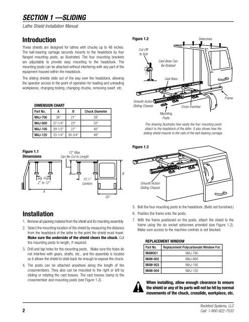
Figure 1.2<br />
Setscrews<br />
These shields are designed <strong>for</strong> lathes with chucks up to 48 inches.<br />
The ball-bearing carriage securely mounts to the headstock by four<br />
flanged mounting posts, as illustrated. The four mounting brackets<br />
are adjustable to provide easy mounting to the headstock. The<br />
mounting posts can be attached without interfering with any part of the<br />
equipment housed within the headstock.<br />
Cut Off<br />
to Suit<br />
Cast Boss Can<br />
Be Rotated<br />
The sliding shields slide out of the way over the headstock, allowing<br />
the operator access to the point of operation <strong>for</strong> loading and unloading<br />
workpieces, changing tooling, changing chucks, removing swarf, etc.<br />
Cast Boss<br />
DIMENSION CHART<br />
Part No. A B Chuck Diameter<br />
MAJ-700 26” 21” 28”<br />
MAJ-800 27-1/4” 23” 32”<br />
MAJ-100 29-1/2” 27” 40”<br />
MAJ-120 33-1/4” 30-3/4” 48”<br />
Smooth-Action<br />
Sliding Chassis<br />
Mounting<br />
Posts<br />
Cross-member<br />
This drawing illustrates how easily the four mounting posts<br />
attach to the headstock of the lathe. It also shows how the<br />
sliding shield mounts to the rails of the ball-bearing carriage.<br />
Frame<br />
Figure 1.1<br />
Dimensions<br />
12” Max.<br />
Can Be Cut to Length<br />
Figure 1.3<br />
Adj. From<br />
2” to 12”<br />
A<br />
15 3 ⁄4”<br />
Centers<br />
B<br />
Smooth-Action<br />
Sliding Chassis<br />
20”<br />
<strong>Installation</strong><br />
1. Remove all packing material from the shield and its mounting assembly.<br />
2. Select the mounting location of the shield by measuring the distance<br />
from the headstock of the lathe to the point the shield must travel.<br />
Make sure the underside of the shield clears the chuck. Cut<br />
the mounting posts to length, if required.<br />
3. Drill and tap holes <strong>for</strong> the mounting posts. Make sure the holes do<br />
not interfere with gears, shafts, etc., and the assembly is located<br />
so it allows the shield to slide back far enough to expose the chuck.<br />
4. The posts can be attached anywhere along the length of the<br />
crossmembers. They also can be mounted to the right or left by<br />
sliding or rotating the cast bosses. The cast bosses clamp to the<br />
crossmember and mounting posts (see Figure 1.2).<br />
5. Bolt the four mounting posts to the headstock. (Bolts not furnished.)<br />
6. Position the frame onto the posts.<br />
7. With the frame positioned on the posts, attach the shield to the<br />
frame using the six socket setscrews provided (see Figure 1.2).<br />
Make sure access to the machine controls is not blocked.<br />
REPLACEMENT WINDOW<br />
Part No.<br />
MAW001<br />
MAW-002<br />
MAW-003<br />
MAW-004<br />
Replacement Polycarbonate Window For:<br />
MAJ-700<br />
MAJ-800<br />
MAJ-100<br />
MAJ-120<br />
When installing, allow enough clearance to ensure<br />
the shield or any of its parts will not be hit by normal<br />
movements of the chuck, crosslide, workpiece, etc.<br />
Rock<strong>for</strong>d Systems, LLC<br />
2 Call: 1-800-922-7533


