KSL-244 | Installation Instructions for Lathe Shields
Create successful ePaper yourself
Turn your PDF publications into a flip-book with our unique Google optimized e-Paper software.
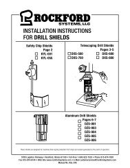
INSTALLATION INSTRUCTIONS FOR<br />
LATHE SHIELDS<br />
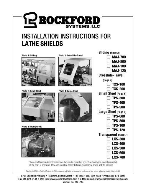
Photo 1: Sliding<br />
Photo 3: Small Steel<br />
Photo 5: Transparent<br />
Photo 2: Crosslide-Travel<br />
Photo 4: Large Steel<br />
Sliding (Page 2)<br />
n MAJ-700<br />
n MAJ-800<br />
n MAJ-100<br />
n MAJ-120<br />
Crosslide-Travel<br />
(Page 4)<br />
n TXS-100<br />
n TXS-200<br />
Small Steel (Page 5)<br />
n TPS-300<br />
n TPS-400<br />
n TPS-500<br />
Large Steel (Page 6)<br />
n TPS-600<br />
n TPS-800<br />
n TPS-100<br />
n TPS-120<br />
Transparent (Page 7)<br />
n LXS-300<br />
n LXS-400<br />
n LXS-500<br />
n LXS-600<br />
n LXS-700<br />
These shields are designed <strong>for</strong> machines that require protection from chips (swarf) and coolant generated<br />
at the point of operation. They also provide a barrier between the machine chuck and the operator.<br />
Copyright © 2019 by Rock<strong>for</strong>d Systems, LLC All rights reserved. Not to be reproduced in whole or in part without written permission. Litho in U.S.A.<br />
5795 Logistics Parkway • Rock<strong>for</strong>d, Illinois 61109 • Toll-Free 1-800-922-7533 • Phone 815-874-7891<br />
Fax 815-874-6144 • Web Site www.rock<strong>for</strong>dsystems.com • E-Mail customerservice@rock<strong>for</strong>dsystems.com<br />
Manual No. <strong>KSL</strong>-<strong>244</strong>
SECTION 1 —SLIDING<br />
<strong>Lathe</strong> Shield <strong>Installation</strong> Manual<br />
Introduction<br />
Figure 1.2<br />
Setscrews<br />
These shields are designed <strong>for</strong> lathes with chucks up to 48 inches.<br />
The ball-bearing carriage securely mounts to the headstock by four<br />
flanged mounting posts, as illustrated. The four mounting brackets<br />
are adjustable to provide easy mounting to the headstock. The<br />
mounting posts can be attached without interfering with any part of the<br />
equipment housed within the headstock.<br />
Cut Off<br />
to Suit<br />
Cast Boss Can<br />
Be Rotated<br />
The sliding shields slide out of the way over the headstock, allowing<br />
the operator access to the point of operation <strong>for</strong> loading and unloading<br />
workpieces, changing tooling, changing chucks, removing swarf, etc.<br />
Cast Boss<br />
DIMENSION CHART<br />
Part No. A B Chuck Diameter<br />
MAJ-700 26” 21” 28”<br />
MAJ-800 27-1/4” 23” 32”<br />
MAJ-100 29-1/2” 27” 40”<br />
MAJ-120 33-1/4” 30-3/4” 48”<br />
Smooth-Action<br />
Sliding Chassis<br />
Mounting<br />
Posts<br />
Cross-member<br />
This drawing illustrates how easily the four mounting posts<br />
attach to the headstock of the lathe. It also shows how the<br />
sliding shield mounts to the rails of the ball-bearing carriage.<br />
Frame<br />
Figure 1.1<br />
Dimensions<br />
12” Max.<br />
Can Be Cut to Length<br />
Figure 1.3<br />
Adj. From<br />
2” to 12”<br />
A<br />
15 3 ⁄4”<br />
Centers<br />
B<br />
Smooth-Action<br />
Sliding Chassis<br />
20”<br />
<strong>Installation</strong><br />
1. Remove all packing material from the shield and its mounting assembly.<br />
2. Select the mounting location of the shield by measuring the distance<br />
from the headstock of the lathe to the point the shield must travel.<br />
Make sure the underside of the shield clears the chuck. Cut<br />
the mounting posts to length, if required.<br />
3. Drill and tap holes <strong>for</strong> the mounting posts. Make sure the holes do<br />
not interfere with gears, shafts, etc., and the assembly is located<br />
so it allows the shield to slide back far enough to expose the chuck.<br />
4. The posts can be attached anywhere along the length of the<br />
crossmembers. They also can be mounted to the right or left by<br />
sliding or rotating the cast bosses. The cast bosses clamp to the<br />
crossmember and mounting posts (see Figure 1.2).<br />
5. Bolt the four mounting posts to the headstock. (Bolts not furnished.)<br />
6. Position the frame onto the posts.<br />
7. With the frame positioned on the posts, attach the shield to the<br />
frame using the six socket setscrews provided (see Figure 1.2).<br />
Make sure access to the machine controls is not blocked.<br />
REPLACEMENT WINDOW<br />
Part No.<br />
MAW001<br />
MAW-002<br />
MAW-003<br />
MAW-004<br />
Replacement Polycarbonate Window For:<br />
MAJ-700<br />
MAJ-800<br />
MAJ-100<br />
MAJ-120<br />
When installing, allow enough clearance to ensure<br />
the shield or any of its parts will not be hit by normal<br />
movements of the chuck, crosslide, workpiece, etc.<br />
Rock<strong>for</strong>d Systems, LLC<br />
2 Call: 1-800-922-7533
SECTION 2 —MOUNTING BRACKETS<br />
<strong>Lathe</strong> Shield <strong>Installation</strong> Manual<br />
Introduction<br />
Mounting brackets are supplied separately <strong>for</strong> any of the shields found<br />
on pages 5-7. These brackets mount to the headstock of the lathe.<br />
Fasteners are not furnished. The transparent and small steel shields<br />
are attached to a zinc-plated extension tube which fits into these<br />
mounting brackets.<br />
There are two principal types of mounting brackets available. Type A<br />
(Figure 2.1) is used <strong>for</strong> mounting to the top or the side of the headstock.<br />
Type B (Figure 2.2) is used <strong>for</strong> mounting to the face of the headstock.<br />
For difficult mounting conditions, the Type A1 bracket (Figure 2.3) may<br />
be used. This bracket incorporates a telescopic height adjustment and<br />
can be swivelled up to an angle of 90° as required.<br />
Figure 2.1<br />
Type A Bracket<br />
Part No. LXS-650<br />
For mounting to the top or<br />
side of the headstock.<br />
Figure 2.2<br />
Type B Bracket<br />
Part No. LXS-652<br />
<strong>for</strong> mounting to the face of the headstock.<br />
2 27 ⁄32”<br />
1 1 ⁄2”<br />
2”<br />
1<br />
⁄2”<br />
1 1 ⁄2”<br />
2 Holes .28” Dia.<br />
1”<br />
Bore<br />
1”<br />
Bore<br />
1”<br />
1 1 ⁄2” Dia.<br />
Figure 2.3<br />
Type A1 Bracket<br />
Part No. LXS-651<br />
<strong>for</strong> extended mounting to the<br />
top or side of the headstock.<br />
1” Bore<br />
1 5 ⁄16”<br />
Extends From 3 1 ⁄2”<br />
to 5”<br />
Shown Extended<br />
3”<br />
2 Holes .32” Dia.<br />
1 1 ⁄4”<br />
90° Movement of Center Piece<br />
if Required<br />
2 21 ⁄64”<br />
1 1 ⁄2”<br />
2”<br />
2 3 ⁄8”<br />
2 Holes .32” Dia.<br />
(Continued on next page.)<br />
Rock<strong>for</strong>d Systems, LLC<br />
Call: 1-800-922-7533 3<br />
3”
SECTION 2 —MOUNTING BRACKET<br />
<strong>Lathe</strong> Shield <strong>Installation</strong> Manual<br />
Introduction (continued)<br />
Figure 2.4<br />
Type B2 Bracket<br />
Part No. LXS-653<br />
<strong>for</strong> mounting to the face of the headstock<br />
when two different sized shields are used.<br />
The Type B2 bracket (Figures 2.4 and 2.5) has a two-socket mounting.<br />
It can be fastened to the face of the headstock where shields with<br />
different diameters are used. It accommodates 3-jaw and 4-jaw<br />
chucks. The inner socket is used <strong>for</strong> the 3-jaw, smaller chuck shield.<br />
When changing over to a larger, 4-jaw chuck, the shield is removed<br />
from the inner socket and replaced by a larger diameter shield inserted<br />
into the outer socket. This accommodates the 4-jaw chuck.<br />
Full dimensions, showing the shield in relation to the chuck, are<br />
illustrated in Figure 6.2 on page 8.<br />
Figure 2.5<br />
3-Jaw Chuck<br />
1<br />
⁄2”<br />
7 1 ⁄2”<br />
3”<br />
2”<br />
1<br />
⁄2” 2 3 ⁄8” 3 3 ⁄4”<br />
1<br />
⁄2”<br />
1 3 ⁄4”<br />
4-Jaw<br />
Chuck<br />
The electrical interlocking bracket assembly (Figure 2.6) includes the Type B bracket <strong>for</strong> mounting to the face of the headstock. This bracket<br />
assembly has an interlock switch that can be interlocked to the lathe’s motor starter circuit. In most cases, the normally open contact of the switch<br />
is used. The cam is then positioned on the mounting rod of the shield so it pushes the wheel of the switch and holds the contact closed while the<br />
shield is down in position. When the shield is lifted up, the contact of the switch is opened, which causes the machine to stop.<br />
Figure 2.6<br />
Part No. FKT-781<br />
Interlocking Bracket Assembly<br />
Interlock Switch Specifications<br />
Contacts..................................................................2 NO and 2 NC<br />
Actuating Directions........................................................................... 4<br />
Switching Ability........................ 3 A @ 230 V AC, 0.27 A @ 230 V DC<br />
Conduit Adapter...................................................................M20 to 1 ⁄2”<br />
Operating Temperature............................................. -13° to 176°F<br />
............................................................................... (-25° to 80°C)<br />
Rock<strong>for</strong>d Systems, LLC<br />
4 Call: 1-800-922-7533
SECTION 3 —CROSSLIDE-TRAVEL<br />
<strong>Lathe</strong> Shield <strong>Installation</strong> Manual<br />
Introduction<br />
These lathe shields mount and travel with the crosslide <strong>for</strong> protection<br />
when machining long workpieces. The steel structure provides<br />
protection from flying chips and coolant. The window permits visibility<br />
into the point of operation. The front portion of the shield hinges up <strong>for</strong><br />
access. This shield is ideal <strong>for</strong> lathes with long beds. Special sizes are<br />
available on request.<br />
<strong>Installation</strong><br />
1. Remove all packing material from the shield and its mounting assembly.<br />
2. Select the mounting bracket location on the crosslide of the<br />
machine and spot holes. Make sure the holes do not interfere with<br />
gears, shafts, etc. (A mounting bracket is not part of the assembly.<br />
It must be ordered separately—see pages 3-4 <strong>for</strong> choices.)<br />
3. Drill and tap two holes <strong>for</strong> the mounting bracket. (See pages 3-4 <strong>for</strong><br />
bracket dimensions or use the bracket as a template.)<br />
4. Fasten the mounting bracket to the crosslide of the lathe using<br />
Allen-head fasteners (not furnished).<br />
5. Assemble the shield to the mounting rod with the fasteners<br />
provided. See Figure 3.2.<br />
6. Slide the mounting rod into the mounting bracket and tighten at the<br />
desired height.<br />
DIMENSION CHART<br />
Part No. A B C D E<br />
TXS-100 17” 8” 10” 12” 12”<br />
TXS-200 23” 11” 12” 14-1/2” 13-3/4”<br />
Figure 3.1Dimensions<br />
A<br />
8 1 ⁄2”<br />
8 1 ⁄2” D<br />
4”<br />
3<br />
⁄4”<br />
E<br />
REPLACEMENT PARTS<br />
Part No. Description<br />
TXW-000 Replacement Polycaronate Window<br />
TXR-000 Mounting Rod and Support Bar<br />
B C<br />
Hinge<br />
20 1 ⁄4”<br />
When installing, allow enough clearance to ensure<br />
the shield or any of its parts will not be hit by normal<br />
movements of the chuck, crosslide, workpiece, etc.<br />
Figure 3.2<br />
Exploded View<br />
Fastener<br />
Support Bar<br />
Hinges up <strong>for</strong><br />
Access<br />
Washer<br />
Setscrew<br />
Fastener<br />
Mounting<br />
Rod<br />
Allen-Head<br />
Fasteners<br />
(not furnished)<br />
LXS-650 Mounting Bracket<br />
(supplied separately). See pages<br />
3-4 <strong>for</strong> other choices.<br />
Rock<strong>for</strong>d Systems, LLC<br />
Call: 1-800-922-7533 5
SECTION 14—SMALL —SLIDINGSTEEL<br />
<strong>Lathe</strong> Shield <strong>Installation</strong> Manual<br />
Introduction<br />
These small steel chuck shields are fabricated of 18-gauge steel and can be used on smaller lathes that have chucks up to 18 1 ⁄4” in diameter.<br />
Each shield is furnished with a 1” x 13” mounting rod which can be cut to length if required. This mounting rod is fastened to the headstock of the<br />
lathe using a mounting bracket (must be ordered separately—see pages 3-4). The mounting rod is also used to hinge the entire shield. The shield<br />
can be lifted and swung up from the operator <strong>for</strong> quick and easy access to the chuck and the part being machined.<br />
<strong>Installation</strong><br />
1. Remove all packing material from the shield and its mounting assembly.<br />
2. Select the mounting bracket location and spot holes on the<br />
machine. Make sure the holes do not interfere with gears, shafts,<br />
etc. (A mounting bracket is not part of the assembly. It must be<br />
ordered separately—see pages 3-4 <strong>for</strong> choices.)<br />
3. Drill and tap two holes <strong>for</strong> the mounting bracket. (See pages 3-4 <strong>for</strong><br />
bracket dimensions or use the bracket as a template.)<br />
4. Fasten the mounting bracket to the headstock of the lathe using<br />
Allen-head fasteners (not furnished).<br />
5. Slide the shield onto the mounting rod and tighten the setscrews.<br />
See Figure 4.1.<br />
6. Slide the mounting rod into the mounting bracket and tighten the<br />
knob. See Figure 4.1.<br />
Note: Maintenance instructions <strong>for</strong> the polycarbonate window are on page 9.<br />
Figure 4.2 Dimensions<br />
Figure 4.1<br />
Mounting<br />
Bracket<br />
1”<br />
C Max Dia.<br />
A<br />
B<br />
1” Bore<br />
1 3 ⁄8”<br />
Window<br />
Four 1 ⁄4-20<br />
Setscrews<br />
8” 7”<br />
D<br />
13” Rod<br />
DIMENSION CHART<br />
Part No. A B C D<br />
TPS-300 12” 7-1/2” 11” 14-3/4”<br />
TPS-400 15-1/2” 9-1/4” 14-1/2” 6-1/4”<br />
TPS-500 19-1/4” 11-1/2” 18-1/4” 8”<br />
When installing, allow enough clearance to ensure<br />
the shield or any of its parts will not be hit by normal<br />
movements of the chuck, crosslide, workpiece, etc.<br />
REPLACEMET PARTS<br />
Part No. Description<br />
FKT-160 13” Mounting Rod<br />
TPW-003 Replacement Window <strong>for</strong> TPS-300<br />
TPW-004 Replacement Window <strong>for</strong> TPS-400<br />
TPW-005 Replacement Window <strong>for</strong> TPS-500<br />
Rock<strong>for</strong>d Systems, LLC<br />
6 Call: 1-800-922-7533
Introduction<br />
SECTION 5—LARGE STEEL<br />
<strong>Lathe</strong> Shield <strong>Installation</strong> Manual<br />
These large steel chuck shields are double-hinged <strong>for</strong> access to the chuck. The front hinged portion can be swung up <strong>for</strong> workpiece changes and<br />
the entire shield can be hinged back <strong>for</strong> changing chucks. The rear mounting rod hinges the entire shield. This shield is furnished with a mounting<br />
rod, a mounting plate, and a support bar.<br />
<strong>Installation</strong><br />
1. Remove all packing material from the shield and its mounting assembly.<br />
2. Select the mounting bracket location on the machine. Make sure<br />
the holes do not interfere with gears, shafts, etc.<br />
3. Spot and drill holes in the mounting plate; spot, drill and tap holes<br />
in the headstock of the lathe.<br />
4. Fasten the mounting bracket to the headstock of the lathe.<br />
(Fasteners not furnished.)<br />
5. Remove the outside guide bushing from the mounting rod. See<br />
Figure 5.1.<br />
6. Slide the shield onto the mounting rod; return the guide bushing<br />
and tighten the setscrews.<br />
7. Spot, drill and tap holes <strong>for</strong> the support bar. Attach the support<br />
bar to the face of the headstock. When the shield is in its normal<br />
operating position, it rests on the support bar. Due to the variation<br />
in headstock dimensions, a specially fabricated support bar may<br />
be required.<br />
Figure 5.2 Dimensions<br />
13 3 ⁄4”<br />
When installing, allow enough clearance to ensure<br />
the shield or any of its parts will not be hit by normal<br />
movements of the chuck, crosslide, workpiece, etc.<br />
Hinge<br />
A<br />
Support Bar<br />
Mounting Rod and Plate<br />
Figure 5.1<br />
Top View of Shield Hinge Front of <strong>Lathe</strong><br />
Headstock<br />
Part No.<br />
A<br />
TPS-600 24”<br />
TPS-800 32”<br />
TPS-100 40”<br />
TPS-120 47-1/2”<br />
Shield<br />
Support Bar<br />
Chuck<br />
REPLACEMET PARTS<br />
Part No. Description<br />
LGR-000 Mounting Rod and Plate<br />
LGR-001 Support Rod<br />
Mounting<br />
Rod<br />
Mounting<br />
Plate<br />
Guide Bushings<br />
Back of <strong>Lathe</strong><br />
(Continued on next page.)<br />
Rock<strong>for</strong>d Systems, LLC<br />
Call: 1-800-922-7533 7
SECTION 6 —TRANSPARENT<br />
<strong>Lathe</strong> Shield <strong>Installation</strong> Manual<br />
Introduction<br />
These transparent chuck shields are mounted to a 1” x 13” mounting<br />
rod which is fastened to the headstock of the lathe using a mounting<br />
bracket (must be ordered separately—see pages 3-4). The semicircular<br />
shield covers half the circumference of the lathe chuck because it is<br />
mounted an equal distance from the chuck center.<br />
Access to the chuck and workpiece is quick and easy. The shield is<br />
lifted up and out of the way <strong>for</strong> the operator.<br />
Figure 6.1<br />
Impact-Resistant Clear<br />
Polycarbonate<br />
Swings up <strong>for</strong><br />
Access<br />
<strong>Installation</strong><br />
1. Remove all packing material from the shield and its mounting assembly.<br />
2. Select the mounting bracket location and spot holes on the machine.<br />
Make sure the holes do not interfere with gears, shafts, etc. (A<br />
mounting bracket must be ordered separately—see pages 3-4.)<br />
3. Drill and tap two holes <strong>for</strong> the mounting bracket. (See pages 3-4 <strong>for</strong> bracket dimensions.)<br />
4. Fasten the mounting bracket to the headstock of the lathe using Allen-head fasteners (not furnished).<br />
5. Slide the mounting rod of the shield into the mounting bracket and tighten the knob.<br />
Mounting Bracket<br />
(See Pages 3-4 <strong>for</strong> Choices)<br />
Note: Maintenance instructions <strong>for</strong> the polycarbonate shield are on page 9.<br />
When installing, allow enough clearance to ensure the shield or any of its parts<br />
will not be hit by normal movements of the chuck, crosslide, workpiece, etc.<br />
Figure 6.2<br />
Dimensions<br />
Type B<br />
Bracket<br />
DIMENSION CHART<br />
DIMENSIONS IN INCHES<br />
Part No. A B C D E<br />
LXS-300 10 12 7 6-1/2 10<br />
Dia. MaX.<br />
B<br />
Inside Dia.A<br />
H<br />
C<br />
H = 1 3 ⁄8”<br />
Type B2<br />
Bracket<br />
LXS-400 14 15-3/4 8-1/2 7-3/4 13<br />
LXS-500 18 19-1/2 10-1/2 7-3/4 13<br />
LXS-600 23-1/2 24-1/4 12-3/4 7-3/4 13<br />
LXS-700 26 28 14-3/4 7-3/4 13<br />
Note: The above part numbers do not include mounting<br />
brackets. See pages 3-4.<br />
REPLACEMENT PARTS<br />
Part No.<br />
DIMENSIONS IN INCHES<br />
LXS-301<br />
Shield <strong>for</strong> LXS-300<br />
2 3 ⁄4”<br />
LXS-401<br />
LXS-501<br />
Shield <strong>for</strong> LXS-400<br />
Shield <strong>for</strong> LXS-500<br />
LXS-601<br />
Shield <strong>for</strong> LXS-600<br />
D<br />
1”<br />
Rod<br />
E<br />
LXS-701<br />
LXS-302<br />
Shield <strong>for</strong> LXS-700<br />
Support Assembly <strong>for</strong> LXS-300<br />
LXS-402 Support Assembly <strong>for</strong> LXS-400, -500, -600 & -700<br />
Support assembly<br />
Support Assembly<br />
FKT-159<br />
10” Mounting Rod <strong>for</strong> LXS-300<br />
FKT-160 13” Mounting Rod <strong>for</strong> LXS-400, -500, -600 & -700<br />
(Continued on next page.)<br />
Rock<strong>for</strong>d Systems, LLC<br />
8 Call: 1-800-922-7533
Using the <strong>Shields</strong><br />
SECTION 7—OTHER CONSIDERATIONS<br />
<strong>Lathe</strong> Shield <strong>Installation</strong> Manual<br />
These shields are intended to deflect objects such as chips and coolant. For protection, position the shield between the point of operation and the<br />
operator. Make sure the shield will not be hit by normal movements of the chuck, crosslide, workpieces, etc. During loading or setup of workpieces,<br />
the shield can be swung out of the way.<br />
Note: Always make sure the shield is installed and maintained in first-class condition to meet the applicable OSHA (Occupational Safety and Health<br />
Administration) or ANSI (American National Standards Institute) standards.<br />
Maintenance of the Polycarbonate<br />
The transparent portions of these shields are made of polycarbonate which was selected <strong>for</strong> its strength and durability under impact. Although it<br />
will scratch if mistreated, it can be kept clear with the following appropriate care.<br />
1. Remove coolant, chips, or debris periodically.<br />
2. Using a clean sponge or soft clean cloth, wash with mild soap or<br />
detergent and lukewarm water.<br />
3. Rinse well with clean water.<br />
4. Hairline scratches or minor abrasions can be removed or minimized<br />
using a mild car polish such as paste wax. A wax coating also makes<br />
cleaning easier.<br />
Do Not rub or wipe with dirty shop towels or scrape with a blade.<br />
Do Not use gasoline, benzine, acetone, or carbon tetrachloride<br />
on the shield.<br />
Do Not use cleaners or powders that contain abrasives, or “dry<br />
rub” abrasive dust to remove coolant, lubricant and chips.<br />
When many shields are used in a plant, spare shields can be kept on hand and exchanged periodically. The shields can be removed from the<br />
machines, carefully washed, and exchanged at a later date.<br />
When operating any turning machine (lathe), the operator must be properly trained and must wear proper<br />
personal protective equipment such as safety glasses with side shields, safety clothing, and safety shoes. The<br />
operator must not wear loose clothing, must not have unrestrained long hair, and must not wear jewelry.<br />
When installing any shield, allow enough clearance to ensure the shield or any of its parts will not be hit by<br />
normal movements of the chuck, crosslide, workpiece, etc.<br />
Warranty, Disclaimer and Limitation of Liability<br />
WARRANTY<br />
Rock<strong>for</strong>d Systems, LLC warrants that this product will be free from defects in material and workmanship <strong>for</strong> a period of 12 months from the date of shipment<br />
thereof. ROCKFORD SYSTEMS LLC’S OBLIGATION UNDER THIS WARRANTY IS EXPRESSLY AND EXCLUSIVELY LIMITED to repairing or replacing such products<br />
which are returned to it within the warranty period with shipping charges prepaid and which will be disclosed as defective upon examination by Rock<strong>for</strong>d<br />
Systems, LLC This warranty will not apply to any product which will have been subject to misuse, negligence, accident, restriction and use not in accordance<br />
with Rock<strong>for</strong>d Systems, LLC’s instructions or which will have been altered or repaired by persons other than the authorized agent or employees of Rock<strong>for</strong>d<br />
Systems, LLC Rock<strong>for</strong>d Systems, LLC’s warranties as to any component part is expressly limited to that of the manufacturer of the component part.<br />
DISCLAIMER<br />
The <strong>for</strong>egoing Warranty is made in lieu of all other warranties, expressed or<br />
implied, and of all other liabilities and obligations on the part of Rock<strong>for</strong>d<br />
Systems, LLC, including any liability <strong>for</strong> negligence, strict liability, or<br />
otherwise, and any implied warranty of merchantability or fitness <strong>for</strong> a<br />
particular purpose is expressly disclaimed.<br />
LIMITATION OF LIABILITY<br />
Under no circumstances, including any claim of negligence, strict liability, or otherwise,<br />
shall Rock<strong>for</strong>d Systems, LLC be liable <strong>for</strong> any incidental or consequential damages, or<br />
any loss or damage resulting from a defect in the product of Rock<strong>for</strong>d Systems, LLC<br />
Rock<strong>for</strong>d Systems, LLC<br />
Call: 1-800-922-7533 9
SECTION 8—RETURN MATERIALS AUTHORIZATION REQUEST FORM<br />
<strong>Lathe</strong> Shield <strong>Installation</strong> Manual<br />
To return material <strong>for</strong> any reason contact the sales department in our organization at 1-800-922-7533 <strong>for</strong> an RMA Number. All return materials<br />
shipments must be prepaid. Complete this <strong>for</strong>m and send with material to Rock<strong>for</strong>d Systems, LLC, 5795 Logistics Parkway, Rock<strong>for</strong>d, IL 61109.<br />
Make sure the RMA Number is plainly identified on the outside of the shipping container.<br />
Company<br />
Address<br />
City State Zip<br />
Phone<br />
Contact Name<br />
Fax<br />
Representative<br />
Items Authorized To Return on RMA No. Original Invoice No. Date<br />
Part No. Serial No. Description<br />
Service Requested Full Credit 25% Restocking Repair & Return Warranty Replacement<br />
Reason <strong>for</strong> return (describe in detail):<br />
Return Materials Authorized by<br />
Date<br />
<strong>KSL</strong><strong>244</strong>/0319


