

KSL-280 | Installation Manual for Adjustable Stroke Detect-A-Finger Drop-Probe Device

Create successful ePaper yourself
Turn your PDF publications into a flip-book with our unique Google optimized e-Paper software.
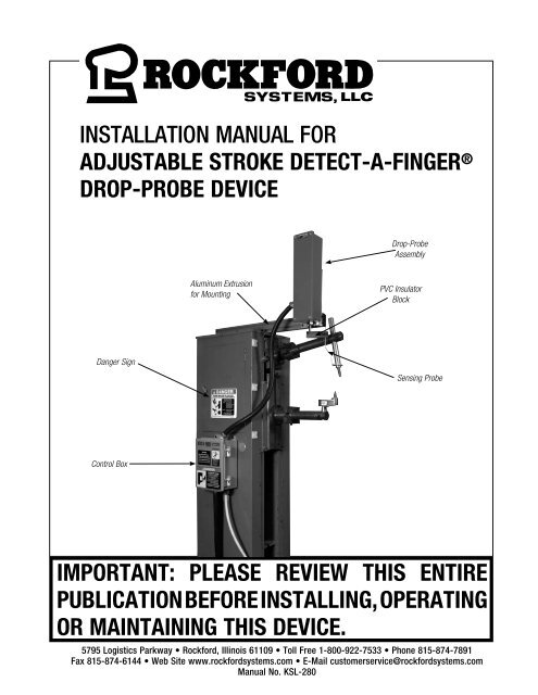
INSTALLATION MANUAL FOR<br />
ADJUSTABLE STROKE DETECT-A-FINGER ®<br />
DROP-PROBE DEVICE<br />
<strong>Drop</strong>-<strong>Probe</strong><br />
Assembly<br />
Aluminum Extrusion<br />
<strong>for</strong> Mounting<br />
PVC Insulator<br />
Block<br />
Danger Sign<br />
Sensing <strong>Probe</strong><br />
Control Box<br />
IMPORTANT: PLEASE REVIEW THIS ENTIRE<br />
PUBLICATION BEFORE INSTALLING, OPERATING<br />
OR MAINTAINING THIS DEVICE.<br />
5795 Logistics Parkway • Rock<strong>for</strong>d, Illinois 61109 • Toll Free 1-800-922-7533 • Phone 815-874-7891<br />
Fax 815-874-6144 • Web Site www.rock<strong>for</strong>dsystems.com • E-Mail customerservice@rock<strong>for</strong>dsystems.com<br />
<strong>Manual</strong> No. <strong>KSL</strong>-<strong>280</strong>
SECTION 1—IN GENERAL<br />
<strong>Adjustable</strong> <strong>Stroke</strong> <strong>Detect</strong>-A-<strong>Finger</strong> ® <strong>Drop</strong>-<strong>Probe</strong> <strong>Device</strong><br />
SECTION 1 - IN GENERAL........................................................................................ 2 - 8<br />
SECTION 2 - INSTALLATION OF COMPONENTS.................................................... 9 - 15<br />
Control Box............................................................................................................... 9<br />
Mini Filter-Regulator Assembly................................................................................ 10<br />
<strong>Drop</strong>-<strong>Probe</strong> Assembly, PVC Insulator Block, and Sensing <strong>Probe</strong>.......................... 10-11<br />
Wiring and Air Tube Connection............................................................................... 12<br />
Other Components That May Be Required.......................................................... 13-14<br />
<strong>Installation</strong> Considerations........................................................................................15<br />
SECTION 3 - POWER-UP PROCEDURES...................................................................... 16<br />
SECTION 4 - TROUBLESHOOTING ........................................................................ 17-18<br />
SECTION 5 - REPLACEMENT PARTS........................................................................... 19<br />
ORDER FORM.............................................................................................................. 20<br />
RETURN AUTHORIZATION FORM................................................................................. 20<br />
Safety Precautions<br />
DANGER<br />
DANGER indicates an imminently hazardous situation which, if not avoided, will<br />
result in death or serious injury.<br />
This safety alert symbol identifies important safety messages in this manual. When<br />
you see this symbol, be alert to the possibility of personal injury, and carefully read<br />
the message that follows.<br />
CAUTION<br />
CAUTION used without the safety alert symbol indicates a potentially hazardous situation<br />
which, if not avoided, may result in property damage.<br />
Efficient and safe machine operation depends on the development, implementation and en<strong>for</strong>cement of a safety program. This program requires,<br />
among other things, the proper selection of point-of-operation guards and safety devices <strong>for</strong> each particular job or operation, a thorough safety<br />
training program <strong>for</strong> all machine personnel, that includes instruction on the proper operation of the machine, the point-of-operation guards and<br />
safety devices on the machine, and a regularly scheduled inspection and maintenance program.<br />
Rules and procedures covering each aspect of your safety program should be developed and published both in an operator’s safety manual, as<br />
well as in prominent places throughout the plant and on each machine. Some rules or instructions which must be conveyed to your personnel and<br />
incorporated into your program include:<br />
DANGER<br />
DANGER<br />
Never place your hands or any part of your body in this machine.<br />
Never operate this machine without proper eye, face and body protection.<br />
Never operate this machine unless you are fully trained, instructed, and have read the instruction manual.<br />
Never operate this machine if it is not working properly – stop operating and advise your supervisor immediately.<br />
Never use a foot switch to operate this machine unless a point-of-operation guard or device is provided and properly<br />
maintained.<br />
Never operate this machine unless two-hand trip, two-hand control or presence sensing device is installed at the proper<br />
safety distance. Consult your supervisor should you have any questions regarding the proper safety distance.<br />
Never tamper with, rewire or bypass any control or component on this machine.<br />
A company’s safety program must involve everyone in the company, from top management to operators, since only as a group can any operational<br />
problems be identified and resolved. It is everyone’s responsibility to implement and communicate the in<strong>for</strong>mation and material contained in catalogs<br />
and instruction manuals to all persons involved in machine operation. If a language barrier or insufficient education would prevent a person from<br />
reading and understanding various literature available, it should be translated, read or interpreted to the person, with assurance that it is understood.<br />
FOR MAINTENANCE AND INSPECTION ALWAYS REFER TO THE OEM’s (ORIGINAL MACHINE MANUFACTURER’S) MAINTENANCE MANUAL<br />
OR OWNER’S MANUAL. If you do not have an owner’s manual, please contact the original equipment manufacturer.<br />
© 2019 Rock<strong>for</strong>d Systems, LLC. All rights reserved. Not to be reproduced in whole or in part without written permission. Litho in U.S.A.<br />
Rock<strong>for</strong>d Systems, LLC<br />
2 Call: 1-800-922-7533
SECTION 1—IN GENERAL<br />
<strong>Adjustable</strong> <strong>Stroke</strong> <strong>Detect</strong>-A-<strong>Finger</strong> ® <strong>Drop</strong>-<strong>Probe</strong> <strong>Device</strong><br />
OSHA’s Act and Federal Regulations<br />
Since the enclosed equipment can never overcome a mechanical<br />
deficiency, defect or malfunction in the machine itself, OSHA<br />
(Occupational Safety and Health Administration) has established certain<br />
safety regulations that the employers (users) must comply with so that<br />
the machines used in their plants, factories or facilities are thoroughly<br />
inspected and are in first-class operating condition be<strong>for</strong>e any of the<br />
enclosed equipment is installed.<br />
1. An Act – Public Law 91 - 596, 91st Congress, S. 2193,<br />
December 29, 1970<br />
Duties:<br />
Sec. 5. (a) Each employer —<br />
(1) shall furnish to each of his employees employment and a place<br />
of employment which are free from recognized hazards that are<br />
causing or are likely to cause death or serious physical harm to<br />
his employees;<br />
(2) shall comply with occupational safety and health standards<br />
promulgated under this Act.<br />
(b) Each employee shall comply with occupational safety and<br />
health standards and all rules, regulations, and orders issued<br />
pursuant to this Act which are applicable to his own actions<br />
and conduct.<br />
2. OSHA’s Code of Federal Regulations, Subpart O, that an<br />
employer (user) must comply with include:<br />
Section 1910.211 Definitions<br />
Section 1910.212 (a) General Requirements <strong>for</strong> all Machines<br />
Section 1910.217 Mechanical Power Presses<br />
Section 1910.219 (b)(1) Mechanical Power-Transmission<br />
Apparatus (Flywheel and Gear Covers)<br />
3. OSHA’s 29 Code of Federal Regulations, Subpart J 1910.147<br />
The Control of Hazardous Energy (Lockout / Tagout)<br />
4. OSHA’s Publications<br />
a. “General Industry Safety and Health Regulations Part 1910,”<br />
Code of Federal Regulations, Subpart O<br />
b. “Concepts and Techniques of Machine Safeguarding,” OSHA<br />
3067, Revised 1992<br />
These publications can be acquired by contacting:<br />
US Department of Labor<br />
Occupational Safety and Health Administration<br />
Washington, DC 20210<br />
ANSI Safety Standards <strong>for</strong> Machines<br />
The most complete safety standards <strong>for</strong> machine tools are published<br />
in the ANSI (American National Standards Institute) B11 series. The<br />
following is a list of ANSI B11 Standards available at the printing of this<br />
publication.<br />
B11.1 Mechanical Presses<br />
B11.2 Hydraulic Presses<br />
B11.3 Power Press Brakes<br />
B11.4 Shears<br />
B11.5 Ironworkers<br />
B11.6 Lathes<br />
B11.7 Cold Headers and Cold Formers<br />
B11.8 Drilling, Milling and Boring<br />
B11.9 Grinding Machines<br />
B11.10 Sawing Machines<br />
B11.11 Gear Cutting Machines<br />
B11.12 Roll Forming and Roll Bending<br />
B11.13 Automatic Screw/Bar and Chucking<br />
B11.14 Coil Slitting Machines<br />
B11.15 Pipe, Tube and Shape Bending<br />
B11.16 Metal Powder Compacting Presses<br />
B11.17 Horizontal Hydraulic Extrusion Presses<br />
B11.18 Coil Processing Systems<br />
B11.19 Per<strong>for</strong>mance Criteria <strong>for</strong> the Design,<br />
Construction, Care and Operation of Safeguards<br />
as Referenced in the Other B11<br />
Machine Tool Safety Standards<br />
B11.20 Safety Requirements <strong>for</strong> Manufacturing<br />
Systems/Cells<br />
B11/TR1 Ergonomic Considerations <strong>for</strong> the Design,<br />
<strong>Installation</strong> and Use of Machine Tools<br />
R15.06 Robotic Safeguarding<br />
These standards can be purchased by contacting:<br />
American National Standards Institute, Inc.<br />
11 West 42nd Street<br />
New York, New York 10036<br />
(212) 642-4900<br />
OR<br />
AMT-The Association of Manufacturing Technology<br />
7901 Westpark Drive<br />
McLean, Virginia 22102-4269<br />
(703) 827-5211<br />
(Continued on next page.)<br />
Rock<strong>for</strong>d Systems, LLC<br />
Call: 1-800-922-7533 3
SECTION 1—IN GENERAL<br />
<strong>Adjustable</strong> <strong>Stroke</strong> <strong>Detect</strong>-A-<strong>Finger</strong> ® <strong>Drop</strong>-<strong>Probe</strong> <strong>Device</strong><br />
National Safety Council Safety<br />
<strong>Manual</strong>s and Data Sheets<br />
Other good references <strong>for</strong> safety on machine tools are the National<br />
Safety Council’s Safety <strong>Manual</strong>s and Data Sheets. These manuals and<br />
data sheets are written by various committees including the Power<br />
Press, Forging and Fabricating Executive Committee. The following<br />
publications are available <strong>for</strong> all types of machines:<br />
MANUALS<br />
Power Press Safety <strong>Manual</strong> - 4th Edition<br />
Safeguarding Concept Illustrations - 6th Edition<br />
Forging Safety <strong>Manual</strong><br />
DATA SHEETS<br />
Bench and Pedestal Grinding Wheel Operations<br />
12304-0705<br />
Boring Mills, Horizontal Metal 12304-0269<br />
Boring Mills, Vertical 12304-0347<br />
Coated Abrasives 12304-0452<br />
Cold Shearing Billets and Bars in the Forging Industry<br />
12304-0739<br />
Degreasing (Liquid), Small Metal Parts 12304-0537<br />
Dies, Setup and Removal of Forging Hammer<br />
12304-0716<br />
Drill Presses, Metalworking 12304-0335<br />
Drills, Portable Reamer 12304-0497<br />
<strong>Drop</strong> Hammers, Steam 12304-0720<br />
Electrical Controls <strong>for</strong> Mechanical Power Presses<br />
12304-0624<br />
Forging Hammer Dies, Setup and Removal of<br />
12304-0716<br />
Forging Presses, Mechanical 12304-0728<br />
Gear-Hobbing Machines 12304-0362<br />
Handling Materials in the Forging Industry 12304-0551<br />
Kick (Foot) Presses 12304-0363<br />
Lathes, Engine 12304-0264<br />
Milling Machines, Metalworking 12304-0364<br />
Planers, Metal 12304-0383<br />
Power Press (Mechanical) Point-of-Operation<br />
Safeguarding, Concepts of 12304-0710<br />
Power Press Point-of-Operation<br />
Safeguarding: Two-Hand Control and<br />
Two-Hand Tripping <strong>Device</strong>s 12304-0714<br />
Power Press Point-of-Operation Safeguarding: Type A<br />
and B Movable Barrier <strong>Device</strong>s 12304-0712<br />
Power Press Point-of-Operation Safeguarding:<br />
Point-of-Operation Guards 12304-0715<br />
Power Press Point-of-Operation Safeguarding:<br />
Presence Sensing <strong>Device</strong>s 12304-0711<br />
Power Press Point-of-Operation Safeguarding:<br />
Pullbacks and Restraint <strong>Device</strong>s 12304-0713<br />
Power Presses (Mechanical), Inspection and<br />
Maintenance of 12304-0603<br />
Power Presses (Mechanical), Removing Pieceparts<br />
from Dies in 12304-0534<br />
Power Press, Setting Up and Removing Dies<br />
12304-0211<br />
Press Brakes 12304-0419<br />
Robots 12304-0717<br />
Saws, Metal (Cold Working) 12304-0584<br />
Shapers, Metal 12304-0216<br />
Shears, Alligator 12304-0213<br />
Shears, Squaring, Metal 12304-0328<br />
Upsetters, 12304-0721<br />
These manuals and data sheets can be purchased by contacting:<br />
National Safety Council<br />
1121 Spring Lake Drive<br />
Itasca, IL 60143-3201<br />
1-800-621-7615 • www.nsc.org<br />
For additional safety in<strong>for</strong>mation and assistance in devising,<br />
implementing or revising your safety program, please contact the<br />
machine manufacturer, your state and local safety councils, insurance<br />
carriers, national trade associations and your state’s occupational<br />
safety and health administration.<br />
Warranty, Disclaimer and Limitation of Liability<br />
WARRANTY<br />
Rock<strong>for</strong>d Systems, LLC. warrants that this product will be free from defects in material and workmanship <strong>for</strong> a period of 12 months from the date<br />
of shipment thereof. ROCKFORD SYSTEMS LLC’S OBLIGATION UNDER THIS WARRANTY IS EXPRESSLY AND EXCLUSIVELY LIMITED to repairing or<br />
replacing such products which are returned to it within the warranty period with shipping charges prepaid and which will be disclosed as defective<br />
upon examination by Rock<strong>for</strong>d Systems, LLC. This warranty will not apply to any product which will have been subject to misuse, negligence,<br />
accident, restriction and use not in accordance with Rock<strong>for</strong>d Systems, LLC.’s instructions or which will have been altered or repaired by persons<br />
other than the authorized agent or employees of Rock<strong>for</strong>d Systems, LLC. Rock<strong>for</strong>d Systems, LLC.’s warranties as to any component part is expressly<br />
limited to that of the manufacturer of the component part.<br />
DISCLAIMER<br />
The <strong>for</strong>egoing Warranty is made in lieu of all other warranties, expressed or<br />
implied, and of all other liabilities and obligations on the part of Rock<strong>for</strong>d<br />
Systems, LLC., including any liability <strong>for</strong> negligence, strict liability, or<br />
otherwise, and any implied warranty of merchantability or fitness <strong>for</strong> a<br />
particular purpose is expressly disclaimed.<br />
LIMITATION OF LIABILITY<br />
Under no circumstances, including any claim of negligence, strict liability, or otherwise,<br />
shall Rock<strong>for</strong>d Systems, LLC. be liable <strong>for</strong> any incidental or consequential damages, or<br />
any loss or damage resulting from a defect in the product of Rock<strong>for</strong>d Systems, LLC.<br />
Rock<strong>for</strong>d Systems, LLC<br />
4 Call: 1-800-922-7533
out <strong>for</strong> Anyone Operating This Machine<br />
<strong>for</strong>e You Operate This Machine<br />
ou Must Read and Understand<br />
These Safety Precautions<br />
Place Your Hands<br />
or Any Part of<br />
Your Body in This<br />
Machine<br />
verse Side <strong>for</strong> Other Safety Precautions.<br />
C-000<br />
OVER<br />
OPERATOR<br />
FETY PRECAUTIONS<br />
DANGER<br />
Operator Safety Precautions Sign<br />
OPERATOR<br />
SAFETY PRECAUTIONS<br />
Handout <strong>for</strong> Anyone Operating This Machine<br />
Be<strong>for</strong>e You Operate This Machine<br />
You Must Read and Understand<br />
These Safety Precautions<br />
SECTION 1—IN GENERAL<br />
<strong>Adjustable</strong> <strong>Stroke</strong> <strong>Detect</strong>-A-<strong>Finger</strong> ® <strong>Drop</strong>-<strong>Probe</strong> <strong>Device</strong><br />
Accompanying this equipment is an 8 1 ⁄2” x<br />
11” operator safety precautions sign, Part No.<br />
KSC-000, <strong>for</strong> anyone operating the machine<br />
where this equipment will be installed. This<br />
precautions sign is to be given to all operators,<br />
including setup people, maintenance<br />
personnel and supervisors.<br />
Place Your Hands<br />
or Any Part of<br />
Your Body in This<br />
Machine<br />
See Reverse Side <strong>for</strong> Other Safety Precautions.<br />
Sign No. KSC-000<br />
OVER<br />
This sign should also be attached to the<br />
machine, readily accessible and visible to<br />
the operator. (A hole in the corner of this<br />
precautions sign is provided <strong>for</strong> attaching<br />
purposes.) Additional copies of these<br />
precautions are available. Please call, write,<br />
fax, or use the order <strong>for</strong>m found on a later<br />
page in this manual.<br />
Front<br />
1<br />
2<br />
3<br />
4<br />
5<br />
6<br />
7<br />
8<br />
Do Not Operate This Machine<br />
Until You Read and Understand the<br />
Following Safety Precautions.<br />
Never operate this machine until you understand that this<br />
machine is dangerous and if you place your hands, or any<br />
part of your body in this machine it could result in the loss of<br />
fingers, limbs or even death.<br />
Never operate this machine without the use of a guard or<br />
safety device that will always protect you from bodily injury.<br />
Never use a foot switch to operate this machine unless<br />
a point-of-operation guard or device is provided and<br />
properly maintained.<br />
Never “ride” the foot pedal or foot switch. Never rest your<br />
foot on top of the foot pedal or inside the foot switch. Always<br />
remove your foot completely from the foot pedal or foot<br />
switch after each cycle and any time you are not intending<br />
to trip the machine.<br />
Always use hand tools <strong>for</strong> feeding or retrieving material<br />
from the point of operation or any other hazardous part of the<br />
machine. Never reach through or into die area <strong>for</strong> any reason.<br />
Never operate this machine unless you feel you have been<br />
fully trained and have received and understand all operating<br />
instructions. Make sure you know how the machine works<br />
and how it is controlled.<br />
Never operate this machine until you test the machine with its<br />
guard or safety device be<strong>for</strong>e you start or restart production.<br />
Do not begin operating the machine unless you are sure the<br />
safeguarding is adjusted properly and working correctly. If you<br />
are not sure call your supervisor.<br />
Never operate this machine if it is not working properly or if<br />
you notice any unusual noise or change in the per<strong>for</strong>mance<br />
of the machine. Stop operating the machine immediately and<br />
advise your supervisor.<br />
9<br />
10<br />
11<br />
12<br />
13<br />
14<br />
15<br />
16<br />
Never operate this machine with pullbacks unless they are<br />
adjusted properly <strong>for</strong> you. Have your supervisor show you<br />
manually that when the ram descends the pullbacks will<br />
pull your fingers clear of any pinch points. Always wear your<br />
wristlets properly and securely.<br />
Never operate this machine with pullbacks without reading<br />
and understanding the instructions. Instructions must be kept<br />
with the pullback device at all times and made available to<br />
you. Obtain, read and follow these instructions.<br />
Never operate this machine unless two-hand trip, two-hand<br />
control or presence sensing device are installed correctly and<br />
at the proper safety distance. Consult your supervisor should<br />
you have any questions regarding the proper safety distance.<br />
Never tamper with, rewire or bypass any control, component<br />
or safeguard on this machine.<br />
Always wear safety glasses, ear protection and any other<br />
personal protection equipment needed when operating this<br />
machine.<br />
Be sure all persons are clear of the machine be<strong>for</strong>e it is<br />
cycled, especially when multiple operators are present. Do<br />
not operate machine unless you and every operator and/or<br />
helper are protected from injury by a guard or safety device.<br />
Always stay alert (don’t daydream) and never operate this<br />
machine while under the influence of alcohol or any other drug<br />
including prescription medications.<br />
Maintenance and Die Set-Up Personnel: Never work on<br />
this machine unless power is off, flywheel is at rest, safety<br />
blocks are used between dies, ram and bolster plate and<br />
all energy (electrical, air, hydraulic, etc.) are in a zero state.<br />
When a language barrier or insufficient<br />
education prevents a person from reading or<br />
understanding the contents of this operator<br />
safety precautions sign, you should either<br />
translate this in<strong>for</strong>mation or have it read or<br />
interpreted to the person. Make sure that<br />
the person understands the in<strong>for</strong>mation. To<br />
order this sign in Spanish, use Part No.<br />
KSC-000S; in French, use Part No. KSC-000F.<br />
These precautions must be reviewed daily.<br />
NOTICE TO EMPLOYER: A copy of this “Operator Safety Precautions” must be given to all operators (including die setup<br />
people, maintenance personnel and supervisors) of this machine. A copy should also be hung on the machine<br />
readily accessible and visible to the operator. Additional copies of this precaution are available upon request.<br />
Just call or write.<br />
IMPORTANT: Where a language barrier or insufficient schooling would prevent a person from reading and understanding<br />
the contents of this Operator Safety Precaution, you should either translate this in<strong>for</strong>mation or have it read or<br />
interpreted to the person, with assurance that it is understood.<br />
THIS PRECAUTION MUST BE REVIEWED DAILY.<br />
Back<br />
Rock<strong>for</strong>d Systems, LLC<br />
Call: 1-800-922-7533 5
Handout <strong>for</strong> Anyone Operating This Machine<br />
Be<strong>for</strong>e You Operate This Machine<br />
You Must Read and Understand<br />
These Safety Precautions<br />
See Reverse Side <strong>for</strong> Other Safety Precautions.<br />
SIGN NO. KSC-000<br />
OVER<br />
SECTION 1—IN GENERAL<br />
<strong>Adjustable</strong> <strong>Stroke</strong> <strong>Detect</strong>-A-<strong>Finger</strong> ® <strong>Drop</strong>-<strong>Probe</strong> <strong>Device</strong><br />
Danger Sign(s) to be Mounted on Machine<br />
Accompanying this equipment is a 5” x 6” polyethylene danger sign, Part No. KSC-055. This sign MUST BE PERMANENTLY<br />
MOUNTED IN A PROMINENT LOCATION on the machine where this equipment is installed. This sign must be in a LOCATION<br />
THAT IS EASILY VISIBLE to the operator, setup person, or other personnel who work on or around this machine. ALWAYS<br />
mount this sign with bolts or rivets when installing the enclosed equipment.<br />
If any danger sign becomes destroyed or unreadable, the sign must be replaced immediately. Contact factory <strong>for</strong> replacement danger sign(s).<br />
Never operate this machine unless danger signs are in place.<br />
Part No. KSC-000 Operator<br />
Safety Precations Sign<br />
OPERATOR<br />
SAFETY PRECAUTIONS<br />
DANGER<br />
Place Your Hands<br />
or Any Part of<br />
Your Body in This<br />
Machine<br />
Front Side<br />
Part No. KSC-055 Danger Sign<br />
(Foot) - Standard<br />
Part No. KSC-055S - Spanish<br />
Part No. KSC-055F - French<br />
OPERATOR<br />
SUGGESTED PROCEDURE FOR<br />
MOUNTING THIS SIGN<br />
SAFETY PRECAUTIONS<br />
THE PURPOSE OF THIS SIGN IS TO<br />
ADEQUATELY WARN ALL PERSONNEL OF THE DANGER<br />
OF BODILY INJURY OR DEATH.<br />
To accomplish this purpose - ALWAYS mount this<br />
sign in the following manner:<br />
(1) Clearly visible to the operator<br />
and other personnel<br />
Handout <strong>for</strong> Anyone (2) At or near Operating eye level This Machi<br />
(3) PERMANENTLY fastened with<br />
bolts or rivets<br />
NEVER OPERATE MACHINE WITHOUT THIS<br />
Be<strong>for</strong>e You DANGER Operate SIGN VISIBLE TO ALL PERSONNEL. This Machine<br />
You Must Read and Understand<br />
These Safety<br />
Reverse Side<br />
Precautions<br />
“Mechanical Power Press Safety” Booklet<br />
A copy of Booklet No. MPPS (Mechanical Power Press Safety) is available upon request. This booklet is copied verbatim from the CFR (Code of<br />
Federal Regulations) and contains all relevant sections of the OSHA standards concerning power presses with which an employer (user) must<br />
comply. The enclosed equipment must be installed, used and maintained to meet these standards. Specifically, any time a foot switch is used, a<br />
suitable point-of-operation safeguard or device must be used to prevent bodily injury. In addition, every press must be provided with a<br />
Place Your Hands<br />
or Any Part of<br />
Your Body in This<br />
Machine<br />
point-of-operation safeguard! Please review this booklet be<strong>for</strong>e installing the enclosed equipment. If you are unfamiliar with these detailed safety<br />
regulations, which include regulations on safeguarding the point of operation properly, you may want to attend our regularly scheduled machine<br />
safeguarding seminars. To obtain detailed in<strong>for</strong>mation about these training seminars, please call, fax, write, or check our Web site. Our telephone,<br />
fax number, Web site, and mailing address are on the front cover of this manual.<br />
See Reverse Side <strong>for</strong> Other Safety Precautio<br />
Rock<strong>for</strong>d Systems, OVER LLC<br />
Sign No. KSC-000<br />
6 Call: 1-800-922-7533
Components in the System<br />
• Control box<br />
• <strong>Drop</strong>-probe assembly<br />
• Mini filter-regulator assembly<br />
• Air tubing (5⁄32” x 25’ PVC tubing)<br />
ADDITIONAL COMPONENTS THAT MAY BE REQUIRED<br />
• Foot switch<br />
• Air cylinder—<strong>for</strong> mechanical to electrical conversion<br />
• Dual-solenoid or single-solenoid air valve assembly<br />
• Air lockout valve<br />
SECTION 1—IN GENERAL<br />
<strong>Adjustable</strong> <strong>Stroke</strong> <strong>Detect</strong>-A-<strong>Finger</strong> ® <strong>Drop</strong>-<strong>Probe</strong> <strong>Device</strong><br />
• Sensing probe<br />
• Aluminum extrusion <strong>for</strong> mounting<br />
• Danger signs<br />
Preliminary Steps Be<strong>for</strong>e <strong>Installation</strong><br />
Be<strong>for</strong>e proceeding with the installation of the enclosed equipment, you should undertake the following preliminary steps.<br />
1. Read and make sure you understand this entire installation manual.<br />
2. Refer to the front cover, other line drawings and photos, then make a sketch of your installation to plan the location of the enclosed equipment<br />
on the machine.<br />
3. Please make sure the machine is in first-class condition. Be<strong>for</strong>e starting any installation, it is essential that the machine is thoroughly<br />
inspected. Be sure all mechanical components and all collateral equipment are in first-class operating condition. Your inspection should<br />
be done according to the machine manufacturer’s installation and maintenance instruction manual. If you have any doubts or questions<br />
concerning the condition of the machine, contact the machine manufacturer <strong>for</strong> assistance. Repair or replace all parts not operating<br />
properly be<strong>for</strong>e proceeding.<br />
Inspection and maintenance programs must be established and implemented to keep machines in first-class condition.<br />
Safety programs must include thorough inspections of each machine on a weekly basis and records kept of these<br />
inspections. Any part of the machine that is worn, damaged or is not operating properly must be replaced immediately or<br />
repaired be<strong>for</strong>e the machine is used.<br />
4. Verify that the machine is in first-class condition and operating properly; shut off all power to the machine. Padlock all electrical and pneumatic<br />
energy in the off position and do not actuate the machine again until the installation of all package components has been completed. Lockout/<br />
tagout energy isolation procedures must always be practiced and en<strong>for</strong>ced.<br />
General Overview<br />
The adjustable stroke DAF-100 <strong>Detect</strong>-A-<strong>Finger</strong> ® drop-probe device is an air/electric system. It is designed to effectively eliminate accidents that<br />
may arise when machine operators must have their fingers in close proximity to the point of operation on welder/riveter machines.<br />
The DAF-100 is a safety device operated by air and cannot function without it.<br />
SYSTEM REQUIREMENTS<br />
Air..............................................30 psi @ 5 cfm minimum<br />
Electrical.....................................100-240 V AC, 47-63 Hz @ 1 Amp<br />
Relay output contacts...................5 Amps @ 250 V (Terminals 15-16 and 17-18)<br />
SEQUENCE OF OPERATION<br />
Upon actuation of the foot switch, the sensing probe travels downward toward the workpiece. As long as there are no obstructions detected by the<br />
sensing probe, the machine will complete its cycle. If the sensing probe detects an obstruction (down to 1⁄4” above the workpiece), the machine<br />
will not be allowed to complete its cycle. Clear the obstruction and reactuate the foot switch to complete the machine cycle.<br />
The sensing probe must be set to the proper safety distance— 1 ⁄4” above the workpiece.<br />
Note: For two-stage machine operation, actuating the foot switch beyond first-stage operation will initiate second-stage operation once the sensing<br />
probe detects that it is free from obstructions.<br />
Rock<strong>for</strong>d Systems, LLC<br />
Call: 1-800-922-7533 7
SECTION 1—IN GENERAL SECTION 2—INSTALLATION OF COMPONENTS<br />
<strong>Adjustable</strong> <strong>Stroke</strong> <strong>Detect</strong>-A-<strong>Finger</strong> ® <strong>Drop</strong>-<strong>Probe</strong> <strong>Device</strong> <strong>Adjustable</strong> <strong>Stroke</strong> <strong>Detect</strong>-A-<strong>Finger</strong> ® <strong>Drop</strong>-<strong>Probe</strong> <strong>Device</strong><br />
Control Box<br />
The DAF-100 system control box consists of an FTL-071 complete PC board<br />
which includes safety relays and pin-type plug-in terminals housed in an 8”<br />
x 6” NEMA enclosure. The control box should be mounted in a convenient<br />
location and should be mounted within two feet of the mini filter-regulator<br />
assembly. The area around the control box should be kept clear and be<br />
easily accessible <strong>for</strong> wiring and maintenance.<br />
Outside View of DAF-100 Control Box<br />
All electrical power and air supply to the machine must be<br />
off be<strong>for</strong>e mounting, wiring, or servicing the control box.<br />
Air Tube<br />
Bulkheads<br />
Inside View of DAF-100 Control Box<br />
4-Pole Safety<br />
Relay<br />
FTF-071<br />
PC Board (Complete)<br />
24-V DC Power<br />
Supply<br />
6-Pole<br />
Safety Relay<br />
Fuse<br />
3 Pole Power Plug<br />
(100-240V AC)<br />
Input/Output<br />
Plug<br />
Rock<strong>for</strong>d Systems, LLC<br />
8 Call: 1-800-922-7533
SECTION 2—INSTALLATION OF COMPONENTS<br />
<strong>Adjustable</strong> <strong>Stroke</strong> <strong>Detect</strong>-A-<strong>Finger</strong> ® <strong>Drop</strong>-<strong>Probe</strong> <strong>Device</strong><br />
SECTION 1—IN GENERAL<br />
<strong>Adjustable</strong> <strong>Stroke</strong> <strong>Detect</strong>-A-<strong>Finger</strong> ® <strong>Drop</strong>-<strong>Probe</strong> <strong>Device</strong><br />
Mini Filter-Regulator Assembly<br />
The mini filter-regulator assembly consists of one mini air filter and two mini air regulators. Each mini filter-regulator assembly is furnished with 25’<br />
of 5⁄32” air tubing (PVC). This mini filter-regulator assembly is used to adjust the air pressure <strong>for</strong> the air cylinder inside the drop-probe assembly.<br />
INSTALLING THE MINI FILTER-REGULATOR<br />
ASSEMBLY<br />
1. Drill and tap holes on the machine where the mini filter-regulator<br />
assembly is to be located (within 2 feet of the control box). Be careful<br />
when drilling holes into the frame of the machine. Avoid internal<br />
components that could affect machine operation.<br />
2. Place one bolt and two 1⁄4” flat washers (not furnished) to each of<br />
the four mounting feet on the mini filter-regulator assembly. These<br />
washers provide the necessary spacing <strong>for</strong> the tubing connectors on<br />
the back of the assembly. (See photo at right.)<br />
3. Measure, cut, and connect two lengths of 5⁄32” air tubing from the<br />
mini filter-regulator assembly to the air tube bulkheads on the outside<br />
of the control box. Make sure the air tube from the left side regulator<br />
is attached to the left air tube bulkhead.<br />
4. Secure the mini filter-regulator assembly to the machine.<br />
<strong>Drop</strong>-<strong>Probe</strong> Assembly, PVC Insulator Block, and Sensing <strong>Probe</strong><br />
The drop-probe assembly consists of an air cylinder and solenoid operated air valve with an adjustable down stop locking collar, limit witch, and<br />
magnetic proximity switch inside a 31⁄4” x 133⁄16” enclosure. A PVC insulator block is also furnished with the assembly.<br />
<strong>Drop</strong> <strong>Probe</strong> Assembly<br />
Air Pressue Gauges<br />
Inside View of <strong>Drop</strong>-<strong>Probe</strong> Assembly<br />
Bolt and<br />
Washers<br />
Space <strong>for</strong><br />
Tubing<br />
Connectors<br />
<strong>Adjustable</strong> Down<br />
Stop Locking Collar<br />
Bottom of <strong>Stroke</strong><br />
Limit Switch<br />
Top of <strong>Stroke</strong><br />
Magnetic Sensor<br />
24-V DC<br />
Pneumatic Valve<br />
Air Tube Fittings<br />
PVC Insulator Block<br />
(Continued on next page.)<br />
Rock<strong>for</strong>d Systems, LLC<br />
Call: 1-800-922-7533 9
SECTION 1—IN GENERAL<br />
<strong>Adjustable</strong> <strong>Stroke</strong> <strong>Detect</strong>-A-<strong>Finger</strong> ® <strong>Drop</strong>-<strong>Probe</strong> <strong>Device</strong><br />
SECTION 2—INSTALLATION OF COMPONENTS<br />
<strong>Adjustable</strong> <strong>Stroke</strong> <strong>Detect</strong>-A-<strong>Finger</strong> ® <strong>Drop</strong>-<strong>Probe</strong> <strong>Device</strong><br />
INSTALLING THE DROP-PROBE ASSEMBLY, PVC INSULATOR BLOCK, AND SENSING PROBE<br />
1. Loosely connect the PVC insulator block to the end of the cylinder rod on the bottom of the drop-probe box. Do not tighten all the way at<br />
this time.<br />
2. Determine vertical or horizontal placement of the drop-probe box. Keep in mind that horizontal mounting will result in the 1” x 2” extrusion<br />
being mounted on the bottom rear of the drop-probe box. Mount the extrusion to the drop-probe box. (See photo below, left.)<br />
NOTE: For welder applications, do not mount the drop-probe box parallel to the upper armature plane. Fabricate a mounting bracket that will<br />
attach to the welder frame and run parallel to the bottom stationary armature instead. Mount the drop-probe box to this fabricated bracket.<br />
For riveter applications, make sure the drop-probe box is mounted parallel to the vertical plane of the top riveting punch.<br />
3. While holding the drop-probe box with the extrusion to the mounting spot on the machine, angle the PVC insulator block towards the work<br />
surface. Make sure the air cylinder rod is fully retracted (up).<br />
4. Secure the drop-probe box assembly to the machine (as close to the work surface as possible).<br />
NOTE: The sensing probe will add additional height to the overall mounting dimensions. If necessary, the PVC insulator block may be shortened<br />
by cutting off the first (outer) position where the sensing probe slides into the PVC block. Do not cut off the third hole between the outer and inner<br />
sensing probe mounting holes—the probe will not be able to be clamped tight!<br />
5. Choose the sensing probe that best suits your application. (See example of sensing probe in photo below, right.) Shape (if using the aluminum<br />
probe) and install the sensing probe. To position the sensing probe, loosen the screw on the down stop locking collar and position the sensing<br />
probe so it is 1⁄4” or less above the point of operation. Tighten the screw on the lock collar.<br />
6. Tie off all wires and air tubes when finished so they do not come in contact with the adjustable down stop locking collar on the air cylinder.<br />
Aluminum<br />
Mounting<br />
Extrusion<br />
Sensing<br />
<strong>Probe</strong><br />
Rock<strong>for</strong>d Systems, LLC<br />
10 Call: 1-800-922-7533
SECTION 2—INSTALLATION OF COMPONENTS<br />
<strong>Adjustable</strong> <strong>Stroke</strong> <strong>Detect</strong>-A-<strong>Finger</strong> ® <strong>Drop</strong>-<strong>Probe</strong> <strong>Device</strong><br />
Wiring and Air Tube Connection<br />
SECTION 1—IN GENERAL<br />
<strong>Adjustable</strong> <strong>Stroke</strong> <strong>Detect</strong>-A-<strong>Finger</strong> ® <strong>Drop</strong>-<strong>Probe</strong> <strong>Device</strong><br />
1. Remove the cover from the drop-probe assembly. Open the door of the control box. Measure and install 1⁄2” flexible conduit between<br />
the control box and drop-probe assembly.<br />
2. Thread the magnetic sensor cable, 18-guage blue stranded wire, and two 5⁄32” air tubes through the flexible conduit to the control<br />
box. Leave enough length out of each box to make it easier <strong>for</strong> connection. Number the blue wires according to the enclosed<br />
electrical schematics.<br />
3. Trim and install all wires to the input/output plug (P2) on the circuit board in the control box.<br />
4. Trim and connect the two air tubes to the two bulkheads on the outside of the control box.<br />
5. Trim and connect all wires in the drop-probe assembly according to the enclosed electrical schematics.<br />
CAUTION<br />
Turn the valves on the two mini regulators down be<strong>for</strong>e turning the main air valve on.<br />
6. Turn on the main air valve and slowly increase the air pressure on the left mini regulator. Note which air tube in the drop-probe<br />
assembly is blowing the air and connect this tube to the bottom air fitting of the air cylinder.<br />
7. Turn the main air supply valve off.<br />
8. Trim and connect the remaining air tube to the air fitting located on the electrical air valve.<br />
9. Tie off all wires and air tubes when finished so they do not come in contact with the adjustable down stop locking collar on the air cylinder.<br />
10. Disconnect the existing foot switch from the machine making note of its location. Wire the foot switch to the input/output plug (P2) on the<br />
circuit board in the control box according to the enclosed electrical schematics.<br />
11. In the vacated spot on the machine where the foot switch was originally connected, run new wires from this point on the machine to the<br />
input/output plug (P2) at terminals 15 and 16 on the circuit board of the control box. If the machine has a second-stage operation, run<br />
the necessary wires from the machine to the input/output plug (P2) at terminals 17 and 18 on the circuit board of the control box. Refer<br />
to the enclosed electrical schematics.<br />
Note: For welder applications, jumper “JMP” should be installed on pins 2 and 3.<br />
For riveter applications, jumper “JMP” should be installed on pins 1 and 2.<br />
12. Run the appropriate machine power (100-240 V AC) and the ground wire into the <strong>Detect</strong>-A-<strong>Finger</strong>® control box. Connect these wires to<br />
plug P1 according to the enclosed electrical schematics.<br />
Rock<strong>for</strong>d Systems, LLC<br />
Call: 1-800-922-7533 11
SECTION 1—IN GENERAL<br />
<strong>Adjustable</strong> <strong>Stroke</strong> <strong>Detect</strong>-A-<strong>Finger</strong> ® <strong>Drop</strong>-<strong>Probe</strong> <strong>Device</strong><br />
SECTION 2—INSTALLATION OF COMPONENTS<br />
<strong>Adjustable</strong> <strong>Stroke</strong> <strong>Detect</strong>-A-<strong>Finger</strong> ® <strong>Drop</strong>-<strong>Probe</strong> <strong>Device</strong><br />
Other Components That May Be Required<br />
If the machine being safeguarded with a DAF-series drop-probe <strong>Detect</strong>-A-<strong>Finger</strong>® has single-stroke capability, the following additional components<br />
may be required to trip or cycle the machine.<br />
AIR CYLINDER (If furnished—See enclosed manual <strong>KSL</strong>-096)<br />
An air cylinder can be used to convert mechanical operation of the machine to electro-pneumatic operation. The cylinder bore and stroke (pull- or<br />
push-type) can be determined from actual machine measurements and the location of attachment to the machine’s linkage. The air cylinder is<br />
controlled by a dual-solenoid air valve; an air lockout valve is used to employ smooth arm movement; and a filter-regulator-lubricator assembly is<br />
also needed.<br />
An RCL-series single-acting, spring-return air cylinder has a standard swivel-clevis mount. Mount the air cylinder in the most logical position so<br />
the yoke can be attached to the machine linkage, with the air inlet oriented toward the dual-solenoid air valve. The main requirement <strong>for</strong> the air<br />
cylinder mounting location is that the piston rod will have a straight, inline pull (or push) when attached to the operating linkage. Adjust<br />
so the air cylinder bottoms at the end of each stroke. Be sure the rod stroke is not too long because it could cause jackknifing of the cylinder. Also,<br />
too much air pressure may damage the operating linkage.<br />
Make certain that the drive yoke and lock nut are located approximately halfway down on the threaded portion of the piston rod in order to provide<br />
up or down adjustment when necessary. Attach one end of the flexible rubber hose from the dual-solenoid air valve into the threaded inlet port on<br />
the air cylinder and tighten firmly.<br />
RCL-Series Air Cylinders<br />
Part<br />
Number<br />
Bore<br />
(Inches)<br />
<strong>Stroke</strong><br />
(Inches)<br />
Lbs. Pull<br />
(@ 75 PSI)<br />
Overall<br />
Length<br />
Pull<br />
RCL-001<br />
1.125<br />
1.0<br />
50<br />
10.25”<br />
RCL-002<br />
1.500<br />
1.0<br />
100<br />
15.75”<br />
Overall Length<br />
RCL-003<br />
2.000<br />
2.0<br />
200<br />
19.75”<br />
MONITORED DUAL-SOLENOID AIR VALVE (If furnished—See enclosed manual <strong>KSL</strong>-285)<br />
Monitored<br />
Dual-Solenoid<br />
Air Valve<br />
Part No.<br />
RCD-140<br />
This three-way, 1⁄4” monitored dual-solenoid air valve is pneumatically checked and is used to operate an air<br />
cylinder. This dual-solenoid air valve should be mounted as close to the air cylinder as possible.<br />
The exhaust air muffler must be kept clean at all times. Never operate the machine unless the<br />
muffler is clean. The muffler must be cleaned on a regular basis.<br />
For safety reasons, do not install any pneumatic devices between the dual-solenoid air valve<br />
and the air cylinder.<br />
SINGLE-SOLENOID AIR VALVE ASSEMBLY (If furnished—See enclosed manual <strong>KSL</strong>-151)<br />
Single-solenoid Air<br />
Valve Assembly Part<br />
No. RCD-006<br />
This single-solenoid air valve is a three-way, normally closed, quick-exhaust type. This assembly consists of the<br />
electric air solenoid valve, exhaust air muffler, steel mounting bracket, and flexible hose.<br />
The exhaust air muffler must be kept clean at all times. Never operate the machine unless the<br />
muffler is clean. The muffler must be cleaned on a regular basis.<br />
Rock<strong>for</strong>d Systems, LLC<br />
12 Call: 1-800-922-7533
SECTION 2—INSTALLATION OF COMPONENTS<br />
<strong>Adjustable</strong> <strong>Stroke</strong> <strong>Detect</strong>-A-<strong>Finger</strong> ® <strong>Drop</strong>-<strong>Probe</strong> <strong>Device</strong><br />
FILTER-REGULATOR-LUBRICATOR (FRL) ASSEMBLY<br />
(If furnished—See enclosed manual <strong>KSL</strong>-208)<br />
SECTION 1—IN GENERAL<br />
<strong>Adjustable</strong> <strong>Stroke</strong> <strong>Detect</strong>-A-<strong>Finger</strong> ® <strong>Drop</strong>-<strong>Probe</strong> <strong>Device</strong><br />
The filter cleans air that goes to the dual-solenoid air valve and air cylinder. The regulator and gauge are used to<br />
adjust air pressure. The lubricator keeps the dual-solenoid air valve and the air cylinder properly lubricated. The FRL<br />
assembly should be mounted in a convenient location on the machine, and if possible, it should be accessible from<br />
floor level. The lubricator should be filled with a good quality lubricant (see OEM’s specifications) to the level indicated<br />
by the maximum fill line on the transparent reservoir. Do not overfill.<br />
Never apply more than 130 psi.<br />
Filter-Regulator-<br />
Lubricator Assembly<br />
Part No. RCL-043<br />
The filter must be kept clean at all times. Never operate the machine unless the air filter is clean.<br />
The lubricator must not be filled while under pressure.<br />
It is recommended that a manual shut-off valve be installed in the main line ahead of the filterregulator-lubricator<br />
assembly and close to the machine <strong>for</strong> convenience and <strong>for</strong> locking out air.<br />
AIR LOCKOUT VALVE (If furnished—See enclosed manual <strong>KSL</strong>-098)<br />
This 1⁄4” air lockout valve is usually attached to the inlet end of an FRL assembly. This three-way valve is<br />
operated with the manual movement of a slide that opens and closes the valve. The valve can only be locked out<br />
when the slide is in the closed position. Downstream air is automatically exhausted when the valve is locked out.<br />
Air Lockout Valve<br />
Part No. RCD-071<br />
FOOT SWITCH (If furnished—See enclosed manual <strong>KSL</strong>-001)<br />
To meet OSHA and ANSI safety requirements, a foot switch must be protected from unintentional<br />
operation. This foot switch pedal is protected on the top and both sides by the cast cover and<br />
the front is protected by the hinged flap. Always follow the wiring schematics <strong>for</strong> proper wiring<br />
connection and be sure to maintain the foot switch in first-class condition.<br />
It is the responsibility of the employer (user) to always provide an appropriate<br />
guard and/or device to prevent bodily injury whenever a foot switch is used to<br />
initiate a machine cycle.<br />
Foot Switch<br />
Part No. CTD-011<br />
The guard and/or device must be properly installed, used, and maintained. The<br />
safeguard must prevent personnel from receiving bodily injuries.<br />
Rock<strong>for</strong>d Systems, LLC<br />
Call: 1-800-922-7533 13
SECTION 1—IN GENERAL<br />
<strong>Adjustable</strong> <strong>Stroke</strong> <strong>Detect</strong>-A-<strong>Finger</strong> ® <strong>Drop</strong>-<strong>Probe</strong> <strong>Device</strong><br />
<strong>Installation</strong> Considerations<br />
PIPING<br />
SECTION 2—INSTALLATION OF COMPONENTS<br />
<strong>Adjustable</strong> <strong>Stroke</strong> <strong>Detect</strong>-A-<strong>Finger</strong> ® <strong>Drop</strong>-<strong>Probe</strong> <strong>Device</strong><br />
1. An air lockout valve must be installed in the air line usually just be<strong>for</strong>e the filter-regulator-lubricator assembly to meet OSHA 29 CFR<br />
1910.147 Lockout/tagout requirements.<br />
2. From the lockout valve, connect at the In threaded opening of the filter-regulator. Try to maintain an appropriate pipe size throughout <strong>for</strong><br />
proper air flow. Connect the piping to the ports using teflon tape on the male threads only. Do not allow tape to enter the interior of the<br />
filter-regulator-lubricator, valve, or air cylinder. Be<strong>for</strong>e applying air pressure, make sure the filter and regulator bowls are at least hand<br />
tight.<br />
3. Most approved pipe or hose can be used on the machine. Make sure the size is consistent throughout the system in order to avoid<br />
restriction. Keep air runs as short as possible.<br />
4. See enclosed filter-regulator-lubricator (FRL) assembly <strong>Manual</strong> No. <strong>KSL</strong>-208 <strong>for</strong> additional details.<br />
CAUTION<br />
All air components require clean air. Blow all lines clean of water, dirt, scale, etc., be<strong>for</strong>e making final connection.<br />
Drain water from filter bowl regularly. Should this bowl refill in a short period of time, it may indicate the need <strong>for</strong> a<br />
larger filter in the main air supply line or an air line dryer system. The air filter must be kept clean at all times. Never<br />
operate the machine unless the air filter is clean and water is drained.<br />
WIRING<br />
National Electrical Code and NFPA 79 practices are usually followed <strong>for</strong> wiring the control system, which includes color-coding and the use of numbered<br />
wire markers on both ends of every wire. Color-coding is black <strong>for</strong> power circuits, red <strong>for</strong> 120-V AC control circuits, white <strong>for</strong> current-carrying ground<br />
(commonly referred to as the neutral), and green <strong>for</strong> any equipment grounding conductor.<br />
The size of wire depends on local ordinances. Number 14 stranded copper wire with an approved insulation is recommended. Do not use solid wire.<br />
Rigid, Sealtite, or any tubular connection media that complies with local ordinance is satisfactory. Complete wiring diagrams are provided <strong>for</strong> connecting<br />
the control and components.<br />
Rock<strong>for</strong>d Systems, LLC<br />
14 Call: 1-800-922-7533
SECTION 3—POWER-UP PROCEDURES<br />
<strong>Adjustable</strong> <strong>Stroke</strong> <strong>Detect</strong>-A-<strong>Finger</strong> ® <strong>Drop</strong>-<strong>Probe</strong> <strong>Device</strong><br />
SECTION 1—IN GENERAL<br />
<strong>Adjustable</strong> <strong>Stroke</strong> <strong>Detect</strong>-A-<strong>Finger</strong> ® <strong>Drop</strong>-<strong>Probe</strong> <strong>Device</strong><br />
Power-Up Procedures<br />
Proceed with caution when per<strong>for</strong>ming the power-up procedures. The machine may cycle unexpectedly.<br />
1. Turn the main electrical power and the main air valve to the machine on.<br />
2. On the mini filter-regulator assembly, set the air pressure on the left regulator to about 15 PSI and the right regulator to 0. The air cylinder<br />
in the drop-probe assembly should be fully retracted (up). If the air cylinder is not in the retracted position, turn off the air supply and<br />
reverse the two air tubes going into the air bulkheads on the outside of the control box. Turn the air supply back on and verify the air<br />
cylinder is in the up position.<br />
3. Actuate the foot switch. The machine should not cycle at this time. If the machine cycles unexpectedly, verify the air pressure on the<br />
right regulator is turned all the way off and that the air cylinder in the drop-probe assembly is in the up position. If the air cylinder in<br />
the drop-probe assembly does not move when the foot switch is actuated, recheck all wiring and air connections. Correct any<br />
mistakes be<strong>for</strong>e proceeding.<br />
4. While actuating the foot switch (and the machine not cycling), slowly increase the air pressure on the right regulator of the mini filter<br />
regulator assembly until the air cylinder extends. The machine should cycle at this time.<br />
NOTE: For welder applications, the sensing probe should extend down to the preset stop position and then immediately return to top.<br />
For riveter applications, the sensing probe should extend down to the preset stop position and remain down through the entire<br />
machine cycle.<br />
5. Verify that all is functioning correctly and then adjust the air pressure on the left and right regulators to increase the speed of air cylinder<br />
operation. Use small increments when adjusting the regulators.<br />
CAUTION<br />
Always try to use the least amount of air pressure on the drop-probe assembly air cylinder. Excessive air<br />
pressure could cause the sensor wire to bend out of shape.<br />
6. Insert the workpiece into the machine and actuate the foot switch. Verify that the sensing probe is stopping at the mandatory 1⁄4” above<br />
the point of operation. Make adjustments to the lock collar if necessary.<br />
7. After all adjustments are made, verify that the <strong>Detect</strong>-A-<strong>Finger</strong>® drop-probe device is working properly. Place an inanimate object—<br />
NOT A FINGER—between the workpiece and sensing probe. Actuate the foot switch and verify that the machine does not cycle.<br />
Do not use a finger as a test object—always use an inanimate object. Do not place the test object under the moving part<br />
of the machine.<br />
8. When verification is complete, you are now ready <strong>for</strong> production.<br />
Rock<strong>for</strong>d Systems, LLC<br />
Call: 1-800-922-7533 15
SECTION 1—IN GENERAL<br />
<strong>Adjustable</strong> <strong>Stroke</strong> <strong>Detect</strong>-A-<strong>Finger</strong> ® <strong>Drop</strong>-<strong>Probe</strong> <strong>Device</strong><br />
SECTION 4—TROUBLESHOOTING<br />
<strong>Adjustable</strong> <strong>Stroke</strong> <strong>Detect</strong>-A-<strong>Finger</strong> ® <strong>Drop</strong>-<strong>Probe</strong> <strong>Device</strong><br />
SYMPTOM 1<br />
After turning on the air supply (but not the electrical power), the sensing probe travels to bottom of stroke.<br />
SOLUTION<br />
Verify all electrical power to the machine is turned off and verify this by using an electrical volt meter. Verify the air supply to the machine<br />
is turned on.<br />
Make sure the right-hand side of the mini air filter-regulator assembly (feeding the drop-probe assembly) is adjusted down to 0 PSI and<br />
the left-hand side is set to around 15 PSI. (Turn adjustment knob counterclockwise to decrease air pressure and clockwise to increase<br />
air pressure.) Verify the air tubes are going to the proper locations on the air cylinder in the drop-probe assembly. Depress the tubing<br />
release ring of the bottom 90º air-tube fitting on the air cylinder and remove the air tube. Depress the tubing release ring of the top 90º<br />
air-tube fitting on the air valve and remove the air tube. Install the tube that is blowing air to the bottom 90º air-tube fitting on the air<br />
cylinder. Install the remaining air tube to the top 90º air-tube fitting on the air valve.<br />
SYMPTOM 2<br />
After turning on electrical power (without actuating the foot switch), the sensing probe travels to bottom of stroke.<br />
SOLUTION<br />
Verify SYMPTOM 1 is not the cause of the problem be<strong>for</strong>e proceeding.<br />
Open the door on the main control box. Using a volt meter set on DC scale, check the DC voltage on terminal 4 (FTS NO) on the P2<br />
connector plug in reference to any terminal 9, 12, or 14 on this same plug (refer to electrical schematics). The meter should read 0 DC<br />
volts. If not, remove electrical power to the machine and recheck the wiring connections on the foot switch limit switch contacts to the<br />
P2 connector plug.<br />
The ‘com’ terminal on the foot switch limit switch must be wired to terminal 3 on P2 connector (FTS COM), the NO contact on the foot<br />
switch limit switch must be wired to terminal 4 on P2 connector (FTS NO). The NC contact on this limit switch must be wired to terminal<br />
5 on P2 connector (FTS NC). Verify that the wiring from the air valve is connected to terminals 12 and 13 on P2 connector.<br />
Turn on the electrical power again (do not actuate the foot switch). Does the air cylinder still travel to bottom of stroke? If YES, check the<br />
voltage on terminals 12 and 13 on P2 connector. The meter should read 0 DC volts. If the meter reads 0 DC volts, replace the electrical<br />
air-solenoid valve in the drop-probe assembly.<br />
SYMPTOM 3<br />
After turning on the electrical power and air supply, the sensing probe does not go to bottom of stroke when the foot switch is actuated.<br />
SOLUTION<br />
Be<strong>for</strong>e proceeding, verify SYMPTOMS 1 and 2 are not the cause of this problem. Open the door on the control box. Actuate the foot<br />
switch to the middle position if the machine has a two-stage operation, or all the way down <strong>for</strong> single-stage operation. Check the DC<br />
voltage on terminal 12 and 13 on P2 connector. The meter should read +24 volts DC. If the meter reads +24 volts DC, turn off electrical<br />
power to the machine and check the wiring again or replace the air-solenoid valve in the drop-probe assembly.<br />
Rock<strong>for</strong>d Systems, LLC<br />
16 Call: 1-800-922-7533
SECTION 4—TROUBLESHOOTING<br />
<strong>Adjustable</strong> <strong>Stroke</strong> <strong>Detect</strong>-A-<strong>Finger</strong> ® <strong>Drop</strong>-<strong>Probe</strong> <strong>Device</strong><br />
SECTION 1—IN GENERAL<br />
<strong>Adjustable</strong> <strong>Stroke</strong> <strong>Detect</strong>-A-<strong>Finger</strong> ® <strong>Drop</strong>-<strong>Probe</strong> <strong>Device</strong><br />
SYMPTOM 4<br />
After depressing the foot switch, the sensing probe goes to bottom of stroke but the machine will not cycle.<br />
SOLUTION<br />
Open the door of the control box. Actuate the foot switch to the middle position if the machine has a two-stage operation, or all the way<br />
down <strong>for</strong> single-stage operation. Check the DC voltage on terminal 9 and 11 on P2 connector. The voltage on terminal 11 should read<br />
+24 volts DC. If not, completely release the foot switch and check the voltage on terminal 11 again. If the meter now reads +24 volts<br />
DC when the probe is in the up position, one of the wires on the mini limit switch inside the drop-probe assembly is connected to the<br />
NC contact. Turn off all electrical power to the machine, remove the door of the drop-probe assembly, and connect the mini limit switch<br />
wire to the proper NO contact.<br />
Once the above problem is corrected, actuate the foot switch to the middle position or all the way down. The device should now be<br />
at the bottom of the stroke. Verify that the down stop locking collar is completely down and resting against the top of the air cylinder.<br />
The down stop locking collar must be down against the top of the air cylinder be<strong>for</strong>e the machine can cycle. If the down<br />
stop locking collar is all the way down and touching the air cylinder, the mini limit switch may need to be adjusted slightly. Note: This<br />
adjustment is very sensitive and should not require much movement. Slightly loosen the two 10-32 hex head screws on the back of<br />
the drop-probe assembly and move the limit switch mounting block closer towards the clamp collar. Retighten the two 10-32 hex head<br />
screws. When the limit switch mounting bracket is properly adjusted, you should hear a slight click sound just be<strong>for</strong>e the clamp collar is<br />
completely down against the top of the air cylinder. If the limit switch is adjusted too far in, it will cause the normal cycle of the machine<br />
to begin be<strong>for</strong>e the sensing probe is at its lowest point. This may be an unsafe condition <strong>for</strong> the operator.<br />
If the machine still does not cycle, check that outputs (terminals 15-16 and 17-18 on P2 connector) are properly interfaced into your<br />
machine cycle control circuit. These outputs are dry contacts and may be used with 24 V DC or 115/240 V AC.<br />
Rock<strong>for</strong>d Systems, LLC<br />
Call: 1-800-922-7533 17
SECTION 1—IN GENERAL<br />
<strong>Adjustable</strong> <strong>Stroke</strong> <strong>Detect</strong>-A-<strong>Finger</strong> ® <strong>Drop</strong>-<strong>Probe</strong> <strong>Device</strong><br />
SECTION 5—REPLACEMENT PARTS<br />
<strong>Adjustable</strong> <strong>Stroke</strong> <strong>Detect</strong>-A-<strong>Finger</strong> ® <strong>Drop</strong>-<strong>Probe</strong> <strong>Device</strong><br />
Main Control Box<br />
Part Number Description<br />
CCM-037 3-Pin Power Plug<br />
CCM-058 20-Pin 10 Plug<br />
FTL-071 PC Board, Complete<br />
RTY-026 Fuse, .500ma<br />
RYC-041 2-Pin Shunt<br />
Part No—FTL-071<br />
PC Board, Complete<br />
Part No—RTY-026<br />
Fuse, .500ma<br />
Part No—RYC-041<br />
2-Pin Shunt<br />
Part No—CCM-037<br />
3-Pin Power Plug<br />
Part No—CCM-058<br />
20-Pin IO Plug<br />
<strong>Drop</strong>-<strong>Probe</strong> Assembly and<br />
Mini Air Filter/Regulator<br />
Part Number<br />
DAF983<br />
DAF984<br />
DAF985<br />
DAF100-03<br />
DAF100-04<br />
DAF100-19<br />
DAF100-20<br />
DAF100-21<br />
FCT-030<br />
FKT009-20<br />
DAF982<br />
DAF973<br />
DAF974<br />
Description<br />
3⁄32” T-Handle Hex Wrench<br />
Mini Limit Switch<br />
Bimba Double Ended Air Cylinder<br />
Limit Switch Mounting Bracket<br />
PVC Insulator Block<br />
Top of <strong>Stroke</strong> Magnetic Sensor<br />
Air Pressure Gauge, Center Mount<br />
Pneumatic Valve<br />
Sensing <strong>Probe</strong>, 5⁄32 x 18” L<br />
20’ of ¼” Air Tubing<br />
Lock Collar<br />
Mini Air Filter<br />
Mini Air Regulator (each)<br />
Part No—DAF100-03<br />
Limit Switch<br />
Mounting Bracket<br />
Part No—DAF984<br />
Mini Limit Switch<br />
Part No—DAF100-19<br />
Top of <strong>Stroke</strong> Magnetic<br />
Sensor<br />
Part No—DAF985<br />
Bimba Double Ended Air<br />
Cylinder<br />
Part No—<br />
DAF982<br />
Lock Collar<br />
Part No—DAF100-21<br />
Pneumatic Valve<br />
Part No—DAF100-04<br />
PVC Insulator Block<br />
Part No—FKT009-20<br />
25’ of 5 ⁄32” Air Tubing<br />
Mini Air Filter and Air Regulators<br />
Part No—DAF100-20<br />
Air Pressure Gauge<br />
Part No—FCT-030<br />
Sensing <strong>Probe</strong>,<br />
5/32 x 18” L<br />
Part No—DAF973<br />
Mini Air Filter<br />
Part No—DAF974<br />
Mini Air Regulator<br />
Rock<strong>for</strong>d Systems, LLC<br />
18 Call: 1-800-922-7533
ORDER FORM FOR SIGNS AND LITERATURE<br />
SECTION 1—IN GENERAL<br />
<strong>Adjustable</strong> <strong>Stroke</strong> <strong>Detect</strong>-A-<strong>Finger</strong> ® <strong>Drop</strong>-<strong>Probe</strong> <strong>Device</strong><br />
This instruction manual references signs and literature available <strong>for</strong> your machines. This order <strong>for</strong>m is <strong>for</strong> your convenience to order additional signs<br />
and/or literature as needed. (This order <strong>for</strong>m is part of your installation manual so please make a copy of it when ordering.)<br />
Company<br />
Address<br />
City State Zip<br />
Phone<br />
Fax<br />
Name Purchase Order No. Date<br />
Part No. Description Quantity Required<br />
<strong>KSL</strong>-<strong>280</strong><br />
<strong>Installation</strong> <strong>Manual</strong><br />
KSC-000<br />
Operator Safety Precaution Sign (English)<br />
KSC-000S Operator Safety Precaution Sign (Spanish)<br />
KSC-000F Operator Safety Precaution Sign (French)<br />
KSC-055<br />
Danger Sign (Foot Switch) 5” x 6” (English)<br />
KSC-055S Danger Sign (Foot Switch) 5” x 6” (Spanish)<br />
KSC-055F Danger Sign (Foot Switch) 5” x 6” (French)<br />
<strong>KSL</strong>-051<br />
Mechanical Power Press Safety Booklet<br />
KST-346<br />
<strong>Detect</strong>-A-<strong>Finger</strong> ® Label (Front Cover)<br />
For prices and delivery, please use address, phone or fax number listed on the front cover of this manual.<br />
Your Signature<br />
Date<br />
To return material <strong>for</strong> any reason contact the sales department in our organization at 1-800-922-7533 <strong>for</strong> an R.M.A. Number. All returned materials<br />
shipments must be prepaid. Complete this <strong>for</strong>m and send with material to 5795 Logistics Parkway, Rock<strong>for</strong>d, IL 61109. Make sure the R.M.A.<br />
Number is plainly identified on the outside of the shipping container.<br />
Company<br />
Address<br />
City State Zip<br />
Phone<br />
Contact Name<br />
Fax<br />
Representative<br />
Items Authorized To Return on R.M.A. No. Original Invoice No. Date<br />
Part No. Serial No. Description<br />
Service Requested: q Full Credit q 25% Restocking q Repair & Return q Warranty Replacement<br />
Reason <strong>for</strong> return (describe in detail):<br />
Return Materials Authorized by<br />
Date<br />
<strong>KSL</strong><strong>280</strong>/0619


