
Create successful ePaper yourself
Turn your PDF publications into a flip-book with our unique Google optimized e-Paper software.
General Information Brake Discs<br />
INTRODUCTION.<br />
The AP Racing range of Ventilated and<br />
Solid Brake Discs have been developed<br />
with the benefi t of unparalleled experience<br />
in brake technology, to meet the severe<br />
demands encountered under Race, Rally<br />
and Road conditions.<br />
RACE:<br />
Our extensive range includes discs to<br />
suit all of the most demanding series in<br />
the world. Teams competing in F1, F3,<br />
WRC, GT and Sports Prototypes, Nascar<br />
and Touring Car Championships use<br />
AP Racing discs.<br />
ROAD:<br />
As well as our successes on the circuits<br />
and stages of the world, AP Racing<br />
develop Disc Braking systems for many<br />
leading volume and specialist High<br />
Performance Vehicle Manufacturers<br />
including Aston Martin, Bentley, Caterham,<br />
HSV, Lotus, Noble and TVR etc...<br />
RESEARCH AND<br />
DEVELOPMENT.<br />
Over the last three years AP Racing has<br />
placed increased emphasis on advanced<br />
research and simulation to complement<br />
the existing technology, test and manufacturing<br />
processes of our Competition<br />
and Road Discs. Product improvement is<br />
continuous using feedback from our new<br />
state of the art dynomometer and track<br />
testing AP Racing are able to offer brake<br />
discs with optimum performance and<br />
cooling characteristics for any applications.<br />
DESIGN.<br />
AP Racing share innovations in the R&D<br />
processes between Race and Road<br />
projects, the basic function is the same for<br />
both although each has different service<br />
requirements.<br />
- Race Discs are submitted to high<br />
braking and thermal loads. These loads<br />
are repeated frequently over many laps<br />
or stages. The service life is short and<br />
noise and comfort are not really an issue.<br />
Race Discs normally employ a separate<br />
disc and bell assembly which are<br />
generally available in two types:<br />
- Light Duty - 2 piece bolted assemblies.<br />
- Heavy Duty - 2 piece fl oating assemblies.<br />
A given disc has to fi t many different<br />
customer cars, so they require custom<br />
mounting bells.<br />
- Road Discs however have relatively<br />
low and infrequent loads, although mass<br />
increases compared to race cars which<br />
generates high braking torques. Road<br />
Discs have comfort and long service life<br />
requirements. Costs of each item also<br />
have to remain low for the OEM and the<br />
end user when replacement time arrives.<br />
Of course there are exceptions, Big<br />
Brake upgrades kits can be fi tted, these<br />
kits are closer to race disc’s than road.<br />
For road cars however, many applications<br />
use 1 piece disc and bell assemblies,<br />
this is due to high volume production on<br />
one type of upright. High performance<br />
vehicles use 2 piece bolted assemblies,<br />
enabling to fi t a heavy duty race disc.<br />
- Light Duty - 1 piece disc and bell<br />
assembly.<br />
- Heavy Duty - 2 piece bolted assemblies.<br />
DEVELOPMENT TOOLS.<br />
AP Racing is now equipped with state of<br />
the art design tools which have enabled<br />
us to study disc performance to a level<br />
not hitherto possible.<br />
- FEA: CFD AND THERMAL STRESS<br />
ANALYSIS.<br />
Thermal simulation enables assessment<br />
of brake disc cooling without having to<br />
build costly prototypes.<br />
AP Racing has reached a high degree of<br />
confi dence using these methods and has<br />
adopted FEA as the base of our design<br />
process, this enables AP Racing to tailor<br />
disc design to a given application.<br />
- DYNOMOMETER TESTING.<br />
Not everything can be modelled yet, so<br />
validation testing is essential. Our proven<br />
dynamometer, has been supplemented<br />
by a second, more powerful machine<br />
equipped with state of the art features.<br />
Two fully operational dyno’s to give us<br />
even more signifi cant test capabilities<br />
and help us demonstrate that AP Racing<br />
Brake Discs are the best. Fig 1, shows 2<br />
Fig 1.<br />
Dynomometer plots which are examples<br />
of the data we can extract: Temperature<br />
and Friction Co-effi cient comparison.<br />
NUMERICAL SIMULATION.<br />
AP Racing has developed unique thermal<br />
simulation software, in order to predict<br />
overall brake system temperatures on a<br />
real life cycle.<br />
This simulation is particularly useful for<br />
selection of brake specifi cations, and<br />
wear predictions for endurance races. It is<br />
able to calculate bulk temperatures and<br />
compare different brake system solutions<br />
for various vehicles and race tracks.<br />
R&D EXAMPLES<br />
Three examples of how this simulation<br />
software has already benefi ted the<br />
AP Racing Disc range.<br />
- ‘J HOOK’ Face Design<br />
One of the most instantly recognisable<br />
features of our new generation of brake<br />
discs is the ‘J Hook’ groove pattern.<br />
Grooves have to perform several tasks:<br />
- Face Cleaning.<br />
- Increase abrasive<br />
friction.<br />
- Cover whole<br />
braking face.<br />
- Avoid creating<br />
stress raisers.<br />
Traditional groove<br />
designs achieve this with straight or<br />
curved groove running from the braking<br />
www.apracing.com +44 (0)24 7663 9595<br />
49
50<br />
Brake Discs<br />
face inside diameter to its outside diameter.<br />
This is very effective, however when<br />
the disc face heats up the groove acts a<br />
like a cold spot. This creates a thermal<br />
distortion on the braking face, which<br />
reduces braking effi ciency. The ‘J hook’<br />
design provides for a constant path of<br />
evenly distorted material on the braking<br />
face, the pad never loses contact with<br />
the braking face, improving the friction<br />
characteristics and brake performance.<br />
- Wide Disc<br />
Technology.<br />
In order<br />
for a disc<br />
to perform<br />
consistently<br />
the disc<br />
must effi ciently transfer heat to the<br />
surrounding atmosphere. This is particularly<br />
true in a racing situation where the<br />
braking events are extreme and frequent.<br />
Numerical simulation using both CFD<br />
and FEA techniques backed up by<br />
extensive dynamometer testing has<br />
allowed AP Racing to arrive at a new<br />
level of understanding of brake thermal<br />
performance and redefi ne disc design<br />
parameters to optimise cooling. We call<br />
this “Wide Disc Technology”.<br />
Wide Disc Technology is in fact a design<br />
tool that allows AP Racing to optimise<br />
disc performance. By redistributing the<br />
material in the disc, the cooling performance<br />
can be signifi cantly improved<br />
without increasing weight or stress.<br />
Dynamometer and vehicle testing have<br />
demonstrated actual temperature<br />
reductions of up to 150°C on some<br />
applications. The Wide Disc Technology<br />
can be applied to any disc brake<br />
application and will show worthwhile<br />
temperature reductions even where the<br />
overall width of the brake package is<br />
limited.<br />
- Strap Drive<br />
Disc<br />
Technology.<br />
This Strap<br />
Drive System<br />
has been<br />
developed by<br />
AP Racing<br />
both for Road and Race applications.<br />
The standard fi tment discs on many<br />
performance cars can suffer from brake<br />
vibrations caused by disc distortion. This<br />
generally occurs on fast road and track<br />
installations.<br />
On many performance cars the typical<br />
standard disc will be a heavy duty<br />
ventilated single piece casting. Couple<br />
this type of rigid disc to a standard hub<br />
and wheel bearing and the result is any<br />
hub distortion / run out will transfer onto<br />
the disc brake faces. This eventually<br />
results in brake vibrations, usually picked<br />
up through the steering wheel.<br />
The strap drive system offers a new take<br />
on the fl oating systems already in the<br />
market place. Strap drive uses a series<br />
of stainless steel straps to locate the disc<br />
to the mounting bell, producing a fl exible<br />
coupling between the hub and the disc<br />
faces. This allows the disc to run true in<br />
the caliper under all conditions and also<br />
permits the disc to expand and contract<br />
without being restricted.<br />
Some current replacement discs in the<br />
market place have evolved from<br />
Motorsport applications, they typically<br />
use a drive bobbin to provide some disc<br />
fl oat and were devised to reduce pad<br />
knock off on race cars. This system can<br />
work on a road application but there are<br />
some major drawbacks that the Strap<br />
Drive has overcome with its simplicity.<br />
Bobbin fl oat discs rely on a series of<br />
drive bobbins moving freely in drive<br />
slots. This movement can create wear<br />
during service and promote noise. The<br />
slots can fi ll up with road / brake debris<br />
causing them to seize. AP Racings strap<br />
couplings can’t suffer from any of these<br />
drawbacks. Therefore Service life, brake<br />
noise and also brake pedal travel are all<br />
improved.<br />
AP Racing has also introduced the strap<br />
drive system into a number of our current<br />
brake kit range.<br />
The key points with strap drive discs.<br />
- Compared with single piece discs the<br />
disc is de-coupled from hub, this allows<br />
disc to align itself perfectly within the<br />
caliper.<br />
- Improved pedal feel and brake response<br />
as a result of improved disc alignment<br />
within caliper.<br />
- Improved pedal feel at elevated<br />
temperatures as disc rotor is able to<br />
expand in a controlled manner with little<br />
infl uence from the disc mounting. This<br />
greatly reduces disc coning.<br />
- Controlled axial fl oat of disc rotor reduces<br />
brake ‘knock-off’ which can result in an<br />
inconsistent pedal feel.<br />
- No free moving parts means that the<br />
wear problems normally associated with<br />
fl oating disc designs is not present.<br />
- No free moving parts means that there<br />
are no clearances to become clogged<br />
with debris and corrosion which would<br />
prevent a conventional fl oating disc from<br />
operating correctly.<br />
- No free moving parts means no<br />
unwanted mechanical noise from discs.<br />
- Disc rotor and strap sub assembly<br />
available as service item for cost effective<br />
servicing.<br />
- Successfully used in race applications.<br />
Important note: When replacing brake<br />
pads with strap drive discs fi tted, do not<br />
push the pistons back in to the caliper<br />
by use of a lever against the discs. If<br />
this is done then the disc straps may be<br />
distorted and this can cause disc runout,<br />
resulting in possible brake vibration<br />
General Information<br />
DISC CHOICE<br />
The choice of a particular size and type<br />
of disc will depend on the characteristics<br />
of the vehicle. Experience with the type<br />
of installation or Racing format is very<br />
important.<br />
AP Racing has a wealth of experience<br />
of all types of Racing and our Technical<br />
Section will be pleased to advise on disc<br />
choice. Some of the main considerations in<br />
this choice are:<br />
HOMOLOGATION AND<br />
REGULATION<br />
In Group A and certain other classes of<br />
Racing, Brake equipment is restricted<br />
to that Homologated by the manufacturer<br />
with the FIA. Where applicable you must<br />
therefore choose a disc size / type which<br />
has been Homologated. E.g. only 4<br />
grooves are allowed in Formula 3.<br />
DISC DIAMETER AND<br />
THICKNESS<br />
Disc diameter and thickness are major<br />
factors in basic stopping power. Usually<br />
the largest diameter disc that can be<br />
installed in a particular wheel profi le is<br />
chosen to maximise braking power unless<br />
low weight, poor tyre adhesion or required<br />
brake balance dictate otherwise.<br />
Disc thicknesses normally increase with<br />
disc diameter and in proportion to vehicle<br />
weight and hence work done and cooling<br />
required. Standard disc sizes should be<br />
used wherever possible as this improves<br />
availability.<br />
NOTES<br />
www.apracing.com +44 (0)24 7663 9595
Disc Castings & Face Types Brake Discs<br />
DISC CASTING TYPES<br />
Details of the various disc castings<br />
types available from AP Racing are<br />
given below to help you choose the<br />
correct disc for your application.<br />
NB. AP Racing do not supply<br />
unmachined castings, as all disc go<br />
through special heat treatments<br />
processes during manufacture.<br />
CP2222<br />
Solid with Int/Bell<br />
Max Dia = Ø280mm<br />
Max Thickness = 22mm<br />
CP3580<br />
Ventilated Curved Vane.<br />
No. of Vanes = 48<br />
Air Gap = 14mm<br />
Max Dia = Ø330mm<br />
Max Thickness = 28mm<br />
CP3781<br />
Ventilated Curved Vane.<br />
No. of Vanes = 48<br />
Air Gap = 17.5mm<br />
Max Dia = Ø356mm<br />
Max Thickness = 36mm<br />
CP3847<br />
Ventilated Curved Vane.<br />
No. of Vanes = 36<br />
Air Gap = 20mm<br />
Max Dia = Ø328mm<br />
Max Thickness = 32mm<br />
CP3930<br />
Ventilated Curved Vane.<br />
No. of Vanes = 30<br />
Air Gap = 15.5mm<br />
Max Dia = Ø343mm<br />
Max Thickness = 36mm<br />
CP4284<br />
Ventilated Curved Vane.<br />
No. of Vanes = 84<br />
Air Gap = 21mm<br />
Max Dia = Ø410mm<br />
Max Thickness = 36mm<br />
CP4448<br />
Ventilated Curved Vane.<br />
No. of Vanes = 48<br />
Air Gap = 10.5mm<br />
Max Dia = Ø295mm<br />
Max Thickness = 36mm<br />
CP4914<br />
Ventilated Curved Vane.<br />
No. of Vanes = 48<br />
Air Gap = 13.5mm<br />
Max Dia = Ø378mm<br />
Max Thickness = 36mm<br />
CP5254<br />
Ventilated Curved Vane.<br />
No. of Vanes = 54<br />
Air Gap = 15.25mm<br />
Max Dia = Ø334mm<br />
Max Thickness = 32mm<br />
CP2589<br />
Ventilated with Int/Bell.<br />
No. of Vanes = 30<br />
Air Gap = 15.25mm<br />
Max Dia = Ø280mm<br />
Max Thickness = 21mm<br />
<strong>CP3581</strong><br />
Ventilated Curved Vane.<br />
No. of Vanes = 48<br />
Air Gap = 19.5mm<br />
Max Dia = Ø356mm<br />
Max Thickness = 36mm<br />
CP3784<br />
Ventilated Curved Vane.<br />
No. of Vanes = 48<br />
Air Gap = 16mm<br />
Max Dia = Ø378mm<br />
Max Thickness = 36mm<br />
CP3860<br />
Ventilated Curved Vane.<br />
No. of Vanes = 60<br />
Air Gap = 18mm<br />
Max Dia = Ø310mm<br />
Max Thickness = 36mm<br />
CP3948<br />
Ventilated Curved Vane.<br />
No. of Vanes = 48<br />
Air Gap = 21mm<br />
Max Dia = Ø330mm<br />
Max Thickness = 36mm<br />
CP4348<br />
Ventilated Curved Vane.<br />
No. of Vanes = 48<br />
Air Gap = 9mm<br />
Max Dia = Ø315mm<br />
Max Thickness = 28mm<br />
CP4540<br />
Ventilated Curved Vane.<br />
No. of Vanes = 28<br />
Air Gap = 9.0mm<br />
Max Dia = Ø315mm<br />
Max Thickness = 28mm<br />
CP5125<br />
Ventilated with Int/Bell.<br />
No. of Vanes = 36<br />
Air Gap = 8mm<br />
Max Dia = Ø282mm<br />
Max Thickness = 23mm<br />
CP5772<br />
Ventilated Curved Vane.<br />
No. of Vanes = 72<br />
Air Gap = 19.5mm<br />
Max Dia = Ø378mm<br />
Max Thickness = 36mm<br />
CP3047<br />
Ventilated Curved Vane.<br />
No. of Vanes = 24<br />
Air Gap = 15.5mm<br />
Max Dia = Ø343mm<br />
Max Thickness = 32mm<br />
CP3718<br />
Ventilated Curved Vane.<br />
No. of Vanes = 48<br />
Air Gap = 17.5mm<br />
Max Dia = Ø378mm<br />
Max Thickness = 36mm<br />
CP3836<br />
Ventilated Curved Vane.<br />
No. of Vanes = 36<br />
Air Gap = 19.5mm<br />
Max Dia = Ø378mm<br />
Max Thickness = 36mm<br />
CP3870<br />
Ventilated Curved Vane.<br />
No. of Vanes = 70<br />
Air Gap = 16.5mm<br />
Max Dia = Ø330mm<br />
Max Thickness = 36mm<br />
CP4054<br />
Ventilated Curved Vane.<br />
No. of Vanes = 54<br />
Air Gap = 19mm<br />
Max Dia = Ø410mm<br />
Max Thickness = 36mm<br />
CP4378<br />
Ventilated Int/Bell.<br />
No. of Vanes = 44<br />
Air Gap = 18mm<br />
Max Dia = Ø378mm<br />
Max Thickness = 40mm<br />
RP4542<br />
Ventilated Curved Vane.<br />
No. of Vanes = 48<br />
Air Gap = 17.5mm<br />
Max Dia = Ø366mm<br />
Max Thickness = 32mm<br />
CP5150<br />
Ventilated with Int/Bell.<br />
No. of Vanes = 40<br />
Air Gap = 18mm<br />
Max Dia = Ø340mm<br />
Max Thickness = 38mm<br />
CP6072<br />
Ventilated Curved Vane.<br />
No. of Vanes = 72<br />
Air Gap = 25.5mm<br />
Max Dia = Ø380mm<br />
Max Thickness = 42mm<br />
Disc Vane<br />
Air Gap<br />
Max<br />
Thickness<br />
CP3575<br />
Ventilated with Int/Bell.<br />
No. of Vanes = 36<br />
Air Gap = 16mm<br />
Max Dia = Ø330mm<br />
Max Thickness = 36mm<br />
CP3770<br />
Ventilated Curved Vane.<br />
No. of Vanes = 24<br />
Air Gap = 6.5mm<br />
Max Dia = Ø280mm<br />
Max Thickness = 17mm<br />
CP3837<br />
Ventilated Curved Vane.<br />
No. of Vanes = 36<br />
Air Gap = 15.25mm<br />
Max Dia = Ø330mm<br />
Max Thickness = 28mm<br />
CP3928<br />
Ventilated Curved Vane.<br />
No. of Vanes = 28<br />
Air Gap = 8.15mm<br />
Max Dia = Ø300mm<br />
Max Thickness = 22mm<br />
CP4136<br />
Ventilated Straight Vane.<br />
No. of Vanes = 36<br />
Air Gap = 9.3mm<br />
Max Dia = Ø276mm<br />
Max Thickness = 28mm<br />
CP4470<br />
Ventilated Curved Vane.<br />
No. of Vanes = 70<br />
Air Gap = 26mm<br />
Max Dia = Ø330mm<br />
Max Thickness = 42mm<br />
CP4670<br />
Ventilated Curved Vane.<br />
No. of Vanes = 70<br />
Air Gap = 22mm<br />
Max Dia = Ø330mm<br />
Max Thickness = 38mm<br />
CP5154<br />
Ventilated Curved Vane.<br />
No. of Vanes = 54<br />
Air Gap = 20.5mm<br />
Max Dia = Ø334mm<br />
Max Thickness = 36mm<br />
DISC FACE TYPES<br />
Disc Grooves and sometimes cross drilling<br />
are frequently used on all racing brake<br />
discs to clean the surface of the pad &<br />
allow gases produced to escape. In doing<br />
so the friction characteristics are modifi ed<br />
different groove and drilling patterns<br />
affect the friction characteristic in different<br />
ways, some affect overall friction and<br />
others the bite or release characteristics &<br />
therefore the best solution is not necessarily<br />
the same for each application. AP Racing is<br />
constantly developing and refi ning disc<br />
face patterns and new variations will be<br />
introduced from time to time. The most<br />
popular face types are detailed below.<br />
P = Plain.<br />
(No grooves or holes).<br />
Mainly used for road<br />
cars where low noise<br />
is vital.<br />
G4,8,12&24 = Grooved.<br />
(Straight forward<br />
facing). The number<br />
specifi es grooves<br />
per face. Traditional<br />
style groove<br />
CG4, 8, 12 & 24 =<br />
Curved Grooves.<br />
(Backward facing)<br />
The number specifi es<br />
grooves per face.<br />
Standard pattern.<br />
CR4, 8, 12 & 24 =<br />
Curved Grooves.<br />
(Backward facing running<br />
out on O/D to clear<br />
debris. Only used on<br />
thick wall discs). The<br />
number specifi es grooves per face.<br />
RD = Radiused<br />
Drilled.<br />
(Cross drilled but with<br />
radiused run out to reduce<br />
noise & improve life compared<br />
with standard cross drilling. Usually used on<br />
Road applications.<br />
D = Cross Drilled.<br />
(Drilled holes chamfered).<br />
Still preferred<br />
with some pad materials<br />
but can compromise<br />
disc life.<br />
GD = Grooved &<br />
Drilled.<br />
Usually used on Road<br />
applications.<br />
RA = J Hook Design.<br />
Gives improved bite<br />
and debris clearance<br />
and reduces distortion /<br />
vibration, outer grooves<br />
run out to O/D.<br />
GA = J Hook Design.<br />
Latest design gives<br />
improved bite & debris<br />
clearance & reduces<br />
distortion / vibration,<br />
outer grooves do not run<br />
out to O/D.<br />
RC = J Hook Design.<br />
As RA design but with 3<br />
hooks across face. This<br />
design gives improved<br />
bite & debris clearance<br />
& reduces distortion /<br />
vibration.<br />
www.apracing.com +44 (0)24 7663 9595<br />
51
52<br />
Brake Discs<br />
DISC MOUNTING<br />
Most racing and many high performance<br />
road brake discs are designed to be<br />
mounted on to the hub or stub axle by<br />
means of a mounting bell. Mounting<br />
bells are usually made from high grade<br />
Aluminium alloy although other materials<br />
can be used. This arrangement is much<br />
lighter than a one piece disc and bell, but<br />
more importantly allows some compliance<br />
to reduce the risk of distortion due to heat<br />
expansion of the disc.<br />
This becomes more important the larger<br />
the disc and is considered essential above<br />
Ø330mm diameter.<br />
There are essentially two methods of<br />
attaching the disc to the bell,‘Bolted’ and<br />
‘Floating’. The method to be used will<br />
depend on the particular application.<br />
BOLTED<br />
For lower duty applications and on smaller<br />
discs a bolted mounting is sometimes<br />
preferred for strength and simplicity<br />
especially for off-road application (e.g.<br />
Rallies) where debris may clog a fl oating<br />
mechanism leading to run-out and disc<br />
vibration. Stiff fl at bells should be avoided<br />
with a bolted mounting.<br />
Standard AP Racing disc mounting hole<br />
size is 6.40 / 6.45mm diameter.<br />
AP Racing offer a range of bolts, nuts<br />
and washers to suit. These are also<br />
available in wheel set kits, see below for<br />
details.<br />
Disc<br />
Mounting<br />
Bell<br />
0.80<br />
7.25<br />
BOLT KITS<br />
Bolt kits available for AP Racing discs<br />
are given in the table below. Bolts, nuts<br />
and washers are also available separately.<br />
AP Racing recommend a bolt/nut<br />
tightening torque for a disc and bell of<br />
14Nm (10.5Lb/ft).<br />
Bolt kit<br />
Part No.<br />
No. of<br />
Bolts<br />
in kit.<br />
Bolt Part No.<br />
(All Bolts ¼”<br />
UNF).<br />
CP2494-24 8 CP2494-116<br />
CP2494-6 12 - .875” long.<br />
CP2494-18 12<br />
CP2494-718<br />
- 1.0” long.<br />
CP2494-22 12<br />
CP2491-331<br />
- 1.0625” long.<br />
Nut Part Number.<br />
CP2494-117 x No of Bolts.<br />
Stainless Steel Washer Part Number.<br />
CP2494-1305- 2 x No of Bolts.<br />
11.05<br />
FLOATING<br />
Discs for heavy duty applications, especially<br />
larger discs, should be mounted to<br />
allow some axial & radial fl oat between<br />
disc & bell. This may be achieved by either<br />
of two methods:- ‘Float in the disc’ ,<br />
‘Float in the bell’ or ‘Strap Drive’..<br />
Radial fl oat allows differential expansion<br />
of disc and bell thus reducing stresses<br />
in the disc and minimising disc cracking<br />
and distortion. The idea of axial fl oat is to<br />
compensate for a certain amount of stub<br />
axle / upright fl ex by allowing the disc to<br />
take up its ideal position within the range<br />
of fl oat thus avoiding ‘Knockback’ of the<br />
caliper pistons. However the fl oat should<br />
not be excessive as disc gyroscopic loads<br />
can cause the same effect that the fl oat<br />
is meant to alleviate.<br />
The amount of axial fl oat will depend<br />
somewhat on the application. In a ‘perfect’<br />
system with minimal disc movement<br />
relative to the Caliper the amount of fl oat<br />
need only be around 0.15 - 0.25mm.<br />
‘FLOAT IN THE DISC’<br />
The AP Racing ‘Float in the Disc’ system<br />
uses a disc with an elongated fl at sided<br />
mounting hole. The harder disc is less<br />
prone to wear than the bell but regular<br />
maintenance / cleaning is required if fl oat<br />
is to be maintained at the original level.<br />
9.55<br />
9.50<br />
15.13<br />
15.00<br />
- Float in the disc Bobbins.<br />
The fl oat in the disc bobbins available for<br />
AP Racing fl oating discs are given in the<br />
table opposite.<br />
- All bobbin kits comprises 12 each of the<br />
following, CP2494-718 bolt, CP2494-117<br />
nut and CP2494-1305 washer and the<br />
specifi ed bobbin.<br />
- The exception to this is CP2494-504K10<br />
which has 10 each of CP2494-331 bolt,<br />
CP2494-117 nut and CP2494-1305<br />
washer.)<br />
- Tightening torque for bolts is 14Nm<br />
(10.5lb/ft).<br />
IDENTIFICATION LETTER<br />
TO BE CLEARLY MARKED<br />
WHERE SHOWN AS LARGE<br />
AS POSSIBLE<br />
Ø14.00<br />
6.45<br />
1 HOLE Ø6.40 THRU<br />
11.10<br />
Ø10.90<br />
Disc Mounting<br />
www.apracing.com +44 (0)24 7663 9595<br />
Disc<br />
Bell<br />
R0.10 MAX<br />
ALL ROUND<br />
Float<br />
‘L’ 2.50<br />
9.45<br />
9.40<br />
Bobbin Part Numbers for ‘Float in Disc’<br />
Mounting. (all Dimensions in mm)<br />
Flange<br />
Thickness.<br />
Bobbin<br />
Part No.<br />
Dim’n<br />
‘L’.<br />
Nom<br />
Float.<br />
Bobbin<br />
Kit Part<br />
No.<br />
4.30 /<br />
4.35.<br />
CP2494-<br />
595MA<br />
4.70 /<br />
4.75<br />
0.4<br />
CP2494-<br />
595K12<br />
4.80 /<br />
4.85.<br />
CP2494-<br />
593MB<br />
5.20 /<br />
5.25<br />
0.4<br />
CP2494-<br />
593K12<br />
5.00 /<br />
5.05.<br />
CP2494-<br />
592MC<br />
5.40 /<br />
5.45<br />
0.4<br />
CP2494-<br />
592K12<br />
5.60 /<br />
5.65.<br />
CP2494-<br />
1341MD<br />
5.80 /<br />
5.85<br />
0.2<br />
CP2494-<br />
1341K12<br />
5.50 /<br />
5.55.<br />
CP2494-<br />
591MH<br />
5.90 /<br />
5.95<br />
0.4<br />
CP2494-<br />
591K12<br />
5.60 /<br />
5.65.<br />
CP2494-<br />
589MJ<br />
6.00 /<br />
6.05<br />
0.4<br />
CP2494-<br />
589K12<br />
5.60 /<br />
5.65.<br />
CP2494-<br />
626ML<br />
6.30 /<br />
6.35<br />
0.7<br />
CP2494-<br />
626K12<br />
6.30 /<br />
6.35.<br />
CP2494-<br />
1342MM<br />
6.50 /<br />
6.55<br />
0.2<br />
CP2494-<br />
1342K12<br />
6.30 /<br />
6.35.<br />
CP2494-<br />
504MP<br />
6.70 /<br />
6.75<br />
0.4<br />
CP2494-<br />
504K10<br />
6.30 /<br />
6.35.<br />
CP2494-<br />
504MP<br />
6.70 /<br />
6.75<br />
0.4<br />
CP2494-<br />
504K12<br />
FLOAT IN THE BELL’<br />
The AP Racing ‘Float in the Bell’ system<br />
has the advantage of being used with<br />
standard bolted discs, fl oat is controlled<br />
by bell thickness. During use some wear<br />
of the bell inevitably occurs which tends to<br />
increase fl oat and requires more frequent<br />
Bell replacement than the Float in the<br />
Disc system.<br />
Bell<br />
Disc<br />
float<br />
- Float in the bell Bobbins.<br />
The bobbin for use with ‘fl oat in the bell’<br />
mounting is CP4015-101.<br />
- Bobbin kit CP2494-29<br />
This bobbin can be bought separately or<br />
in a kit CP2494-29 which contains the<br />
bobbins, bolts, nuts & washers x 12.<br />
NB. Recommended bell fl ange thickness<br />
for use with this bobbin is 8.00 / 8.05 to<br />
give 0.15 / 0.25mm fl oat.<br />
1 HOLE<br />
6.45<br />
Ø<br />
6.40 THRU<br />
Ø18.00<br />
R0.10 MAX<br />
ALL ROUND<br />
8.25 / 8.20 2.50<br />
11.96<br />
11.92<br />
IDENTIFICATION LETTER TO BE CLEARLY MARKED<br />
WHERE SHOWN AS LARGE AS POSSIBLE<br />
5.00<br />
WIDE BOBBINS<br />
“Wide Disc” Technology, some discs use<br />
the bobbins listed below.<br />
DIM’N ‘A’ DIM’N ‘B’ ±0.25<br />
±0.025<br />
19.05 ±0.25<br />
11.96 / 11.92<br />
A<br />
¼”-28UNF-2A<br />
BOTH SIDES<br />
CHMF 1ST<br />
THREADS x 45°<br />
DIM’N ‘C’<br />
±0.025<br />
FULL THREAD<br />
A<br />
10.00<br />
±0.25<br />
Bobbin Kits<br />
for Wide Discs.<br />
Dim’n Dim’n Dim’n Kit<br />
‘A’ ‘B’ ‘C’ Part No.<br />
5.425 25.4 10.9 CP4015-125MC<br />
6.025 25.4 10.9 CP4015-126MD<br />
6.725 25.4 7.9 CP4015-112MP<br />
10.00
General Information Brake Discs<br />
DISC OPERATING ADVICE<br />
This section on operating advice has been<br />
produced as a guide only, as many<br />
formula or racing series may differ.<br />
DISC TEMPERATURES<br />
In order to achieve optimum racing brake<br />
performance and prolong disc life it is<br />
essential that the brakes operate at the<br />
correct temperature. In general discs<br />
should run at similar temperatures front<br />
and rear and from side to side, dis-similar<br />
temperatures will lead to varying brake<br />
balance. Temperature balance can be<br />
checked as soon as the car stops in the<br />
pit lane using a Pyrometer such as<br />
AP Racing Pyrometer kit CP2640-24 (see<br />
below). However a pyrometer reading is<br />
not a good indicator of disc operating<br />
temperature which decays rapidly with time<br />
when the brakes are not being applied.<br />
Under racing conditions disc bulk temperatures<br />
should normally be maintained<br />
in the range 400°C to 600°C for best<br />
performance. Disc face peak tempertures<br />
may be higher but should not exceed<br />
the maximum recommended for the pad<br />
material being used.<br />
An effective method of checking maximum<br />
disc operating temperature is by using<br />
temperature paints applied to the disc. A<br />
suitable paint kit can be obtained under<br />
AP Racing Part Number CP2649-1, this<br />
kit contains three paints, Green (430°C),<br />
Orange (560°C) and Red (610°C) plus<br />
thinners and brushes. When assessing<br />
brake temperatures it is important to<br />
complete several successive laps (5 or<br />
preferably 10) at race speeds and<br />
vehicle weight to allow temperatures to<br />
stabilise at a representative level.<br />
Typically when running within the correct<br />
temperature range the Green paint (430°)<br />
will turn throughout, the Orange paint<br />
(560°C) 50% to 100% throughout and the<br />
Red paint (610°C) turned up to 5mm from<br />
each brake face. If the Red paint (610°C)<br />
turns throughout, the discs are running<br />
too hot. Circumferential disc face ridges<br />
are also an indication of running too hot.<br />
Circuits and drivers vary enormously in<br />
the amount of work they demand from the<br />
brakes and therefore the brake system<br />
has to be tuned for each circuit by<br />
adjustment of the cooling airfl ow. The<br />
temptation to over cool the disc should<br />
be resisted. The aim is to keep the<br />
temperature as stable as possible<br />
within the working temperature range.<br />
High maximum to low minimum temperature<br />
cycles are the enemy of disc life and<br />
cause performance variations.<br />
TEMPERATURE<br />
MEASUREMENT<br />
- DIGITAL READ-OUT<br />
PYROMETER<br />
CP2640-24 Digital pyrometer<br />
for brake, disc and tyre<br />
temperatures. High accuracy display reads<br />
in centigrade. The unit comes complete<br />
with probes for both Brake Discs and<br />
Tyres in a heavy duty carry case.<br />
- THERMAL PAINT KITS<br />
CP2649-1 kit comprises<br />
of three paints for<br />
monitoring peak Brake<br />
Disc temperatures.<br />
The three paints are:-<br />
- Green which changes colour to White<br />
at 430°C.<br />
- Orange which changes colour to Buff at<br />
560°C.<br />
- Red which changes colour to White at<br />
610°C.<br />
The kit also comprises, one bottle of<br />
thinners and three brushes.<br />
- BRAKE CALIPER<br />
TEMPERATURE STRIPS<br />
CP2650-11 Temperature<br />
indicator strips for<br />
monitoring caliper temperatures.<br />
- Temperature range 149°C to 260°C<br />
- Each packet contains 10 strips.<br />
- TEMPERATURE<br />
RECORDING PAD<br />
CP2640-25 Allows the<br />
user to record<br />
temperature data for<br />
Brake Discs and Brake Calipers.<br />
DISC COOLING<br />
A good source of cooling air should be<br />
supplied preferably through the upright to<br />
the disc throat. A typical venting cross<br />
section of 100cm² (16in²) is usually<br />
suffi cient. The pick up should preferably<br />
be in an area of clean high pressure air<br />
fl ow and the ducting should be arranged<br />
to avoid sharp bends or changes in section<br />
which may choke the air fl ow. Careful<br />
design of the Mounting Bell is important<br />
in achieving effective disc cooling and<br />
avoiding problems.<br />
Typically 80% of the airfl ow should be<br />
directed up the disc vents and 10% up<br />
each face of the disc. This ratio can<br />
considerably in practice but it is important<br />
that both disc faces are cooled equally<br />
by adjusting the air gaps.<br />
Unequal face temperatures can lead to<br />
disc distortion and a long pedal. Lightening<br />
holes in the bells should be avoided as<br />
available cooling air can be lost without<br />
cooling the disc.<br />
DISC BEDDING<br />
All cast iron brake discs need to be<br />
bedded-in to ensure heat stabilisation and<br />
improve resistance to cracking. Cracks or<br />
even disc failure can occur during the<br />
fi rst few heavy stops if careful bedding is<br />
not carried out. AP Racing recommend<br />
the following procedure:<br />
1) If ducts are fi tted they should be ¾<br />
blanked off.<br />
2) Use previously bedded pads.<br />
3) For a minimum of 15Km use brakes<br />
gently at fi rst from initially low speeds<br />
- Progressively raise speed to normal<br />
racing speed but still using gentle<br />
applications.<br />
4) For the fi nal 2 or 3 applications brakes<br />
can be used quite heavily.<br />
5) If AP Racing thermal paints are used<br />
then only the Green paint (430°C) should<br />
have fully turned to white and maybe<br />
also just the Orange paint (560°C) on<br />
the outside edges of the discs during the<br />
bedding procedure.<br />
6) Allow to cool.<br />
7) AP Racing offer a pre-bedding service<br />
at nominal extra charge. This ensures that<br />
discs are bedded consistently assuring<br />
better performance & life.<br />
Contact AP Racing for details.<br />
SAFETY AND CARE OF DISCS<br />
Cast iron brake discs should not normally<br />
be operated at bulk temperatures in<br />
excess of 610°C and above rotational<br />
speeds of 3000 revolutions per minute.<br />
Discs must be regularly and frequently<br />
inspected for excessive heat crazing and<br />
cracking. Discs with cracks emanating<br />
from mounting holes / slots, inside<br />
diameter, scallops, or outside diameter<br />
should be changed immediately. After<br />
heavy and prolonged use some surface<br />
crazing will often be evident, if this turns<br />
into distinct surface cracks which are<br />
radiating towards the inside or outside<br />
diameter the disc should be changed.<br />
IF IN DOUBT REPLACE.<br />
DISC RUBBING DEPTHS<br />
(SWEPT DEPTH)<br />
It is important to match the swept area of<br />
the disc to the Pad/Caliper combination<br />
that is intended to be used, to avoid any<br />
large cold areas which could lead to disc<br />
distortion. To make this easier the radial<br />
depth of all AP Racing brake pads is<br />
incorporated into the part number (the “D”<br />
Number e.g. D46, D50 & D54). Normally<br />
the Pad / Caliper is positioned so that the<br />
top edge of the pad is level with the nominal<br />
disc outside diameter. However it is<br />
normal to make the eye diameter on the<br />
inboard face (Non mounting side) slightly<br />
smaller in diameter than the mounting<br />
side to match the thermal characteristics<br />
of the two disc faces and avoid distortion<br />
in use. The amount of this under- hang<br />
will vary according to the installation and<br />
is part of the disc designers art, but in<br />
depth thermal analysis carried out by<br />
AP Racing shows that 2mm radius (4mm<br />
on diameter) is suffi cient in most cases.<br />
N.B. THE PAD SHOULD NEVER<br />
OVERHANG THE DISC AS THIS WILL<br />
LEAD TO A NUMBER OF BRAKING<br />
DIFFICULTIES.<br />
www.apracing.com +44 (0)24 7663 9595<br />
53
54<br />
Brake Discs<br />
DISC HANDING.<br />
RIGHT / LEFT HAND IDENTIFICATION<br />
Most AP Racing brake discs feature curved vanes and are<br />
handed. They should be installed with the cooling vanes running<br />
back from the inside to outside diameters in the direction of<br />
rotation as indicated in the sketch below.<br />
DISC ROTATION<br />
VEHICLE<br />
DIRECTION<br />
DISC ROTATION<br />
LEFT HAND DISC RIGHT HAND DISC<br />
PART NUMBERING<br />
When ordering discs please use the correct part number<br />
wherever possible. An example part number is explained<br />
below:- All AP Racing brake discs are individually marked with<br />
the following information:-<br />
PART NUMBER EXPLANATION<br />
Basic Disc<br />
(casting) Type<br />
Disc Face Suffi x<br />
(see below)<br />
<strong>CP3581</strong> - <strong>1042</strong> <strong>CG8</strong> <strong>B1</strong><br />
Stroke Number Bedding<br />
(if applicable)<br />
HANDING<br />
- Even Stroke Numbers are Right Hand<br />
- Odd Stroke Numbers are Left Hand<br />
FACE TYPES<br />
- P = Plain<br />
- D = Drilled Face<br />
- G = Straight Grooves G3 = When G appears with<br />
a digit, this denotes the number of grooves<br />
per face on the disc. e.g. G4 / G6 / <strong>CG8</strong> /<br />
CR12 etc.<br />
- CG = Curved Grooves<br />
- GD = Grooved & Drilled<br />
- CR = Curved Grooved backward facing running out<br />
to O/D.<br />
- RD = Radius Drilled<br />
- SD = Similar to RD but with smaller holes.<br />
- RA = J Hook Design, grooves run-out.<br />
- GA = J Hook Design, grooves do not run-out.<br />
- RC = J Hook as GA but with 3 hooks across face.<br />
- <strong>B1</strong> = A “B” and a Number added to the end of the<br />
part number i.e.<strong>CP3581</strong>-<strong>1042</strong>DB? means the<br />
disc has been pre-bedded with a particular<br />
pad material.<br />
General Information<br />
CUSTOMER NOTES<br />
www.apracing.com +44 (0)24 7663 9595
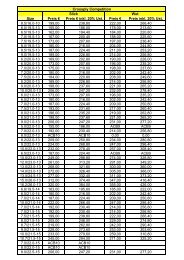
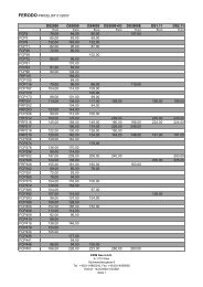
Ventilated Discs Brake Discs<br />
DISC LISTINGS.<br />
The variety of disc options available provide the solution for virtually every<br />
Racing and High Performance Road application. The discs illustrated in these<br />
sections are a selection of discs from the range and have been listed by<br />
Diameter, Thickness and Mounting Details for convenience. If you are unable<br />
to satisfy your requirements from the Discs listed then please contact AP Racing<br />
Technical Section for guidance.<br />
VENTILATED BRAKE DISCS<br />
This section on Ventilated Brake Discs provides dimensional details, as well as<br />
information on face types and the weight of the most popular discs from the<br />
AP Racing disc range. Not all discs are listed, should you require a disc with<br />
particular dimensions which is not listed please contact the AP Racing<br />
Technical Section for assistance.<br />
Discs which have are highlighted are from the preferred disc<br />
range, which offers improved availability and pricing. Please contact<br />
AP Racing if you require more information.<br />
www.apracing.com +44 (0)24 7663 9595<br />
‘ØC’ Eye Dia<br />
‘B’<br />
Thickness<br />
Airgap<br />
‘ØD’ Flange Inside Dia<br />
‘ØA’ Outside Dia<br />
‘H’<br />
Flange<br />
Thickness<br />
Nominal Dimensions in (mm)<br />
‘A’<br />
Outside<br />
Dia.<br />
‘B’<br />
Thickness<br />
Mounting Details<br />
‘M’<br />
Fixing<br />
No.<br />
P.C.D.<br />
type.<br />
Ø.<br />
‘C’<br />
Eye<br />
Ø.<br />
‘D’<br />
Inside<br />
Flange<br />
Ø.<br />
‘H’<br />
Mtg.<br />
Flange<br />
Ø.<br />
Max<br />
Pad<br />
Depth.<br />
No.<br />
of<br />
Vanes.<br />
Air<br />
Gap.<br />
Weight<br />
Kg.<br />
Face<br />
Types<br />
Available.<br />
Comments.<br />
Part<br />
Numbers.<br />
254.0 21.0 139.7 6 Bolted 6.4 154.9 125.8 5.6 D46 36 9.3 3.2 G4 CP4136-568<br />
257.0 21.0 139.7 6 Bolted 6.4 154.9 125.8 5.6 D51 36 9.3 3.6 G4 CP4136-86<br />
260.0 25.4 139.7 6 Bolted 6.4 154.9 125.8 4.8 D51 48 10.5 G4<br />
Mtg Flange<br />
Stepped in 1.2mm<br />
CP4448-226/7<br />
264.0 21.0 139.7 6 Bolted 6.4 154.9 125.8 5.6 D51 36 9.3 3.7 G4 CP4136-208<br />
16.0 162.0 8 Bolted 6.4 180.7 145.0 4.35 D43 24 6.5 CG4 CP3770-1016/7<br />
267.0 21.0 139.7 6 Bolted 6.4 155.0 125.8 5.6 D54 36 9.3 4.4 G4 CP4136-48<br />
28.0 139.7 6 Bolted 6.4 155.0 125.8 4.6 D54 48 10.5 G4 CP4448-81/2<br />
278.0<br />
16.0<br />
16.0<br />
176.1<br />
181.5<br />
8<br />
8<br />
Bolted<br />
Floating<br />
8.45<br />
/<br />
187.4<br />
194.0<br />
156.0<br />
158.0<br />
4.5<br />
4.42<br />
D44<br />
D38<br />
24<br />
24<br />
6.5<br />
6.5<br />
2.5<br />
2.4<br />
G4<br />
CG4<br />
Bobbin CP2494-<br />
595MA<br />
CP3770-1002/3<br />
CP3770-1014/5<br />
17.0 171.4 8 Floating / 191.4 146.5 4.42 D43 24 6.5 2.9 <strong>CG8</strong><br />
Bobbin CP2494-<br />
595MA<br />
CP3770-1018/9<br />
17.0 176.8 8 Bolted 6.5 193.5 159.0 4.7 D43 24 6.5 2.5 G8 CP3770-1012/3<br />
20.0 176.8 8 Floating / 192.0 154.0 5.0 D44 48 9.0 D/G4/G8<br />
Bobbin CP2494-<br />
592MC<br />
Mtg Flange<br />
CP4348-862/3<br />
21.0 176.8 8 Bolted 6.4 192.0 159.3 4.8 D44 48 10.5 G4 Stepped out CP4448-746/7<br />
280.0 22.2 165.1 8 Bolted 6.4 180.3 152.0 4.6 D50 48 10.5 G4<br />
1.2mm<br />
CP4448-752/3<br />
23.0 176.8 8 Bolted 6.4 192.0 159.3 4.8 D44 48 10.5 G4 CP4448-744/5<br />
25.4 158.8 8 Bolted 6.4 174.0 141.0 4.8 D51 48 10.5 G4<br />
Mtg Flange<br />
Stepped in 1.2mm<br />
CP4448-160/1<br />
25.4 176.8 8 Bolted 6.4 192.0 159.3 4.9 D44 30 12.9 4.0 <strong>CG8</strong> Pro 5000+ Disc CP5000-312/3<br />
25.4 176.8 8 Floating / 192.0 154.0 5.0 D44 48 14.0 3.5 G4/G8 CP3580-814/5<br />
25.4 177.8 12 Bolted 6.4 197.0 164.0 5.8 D41 48 10.5 G4 CP4448-856/7<br />
25.4 177.8 8 Bolted 6.4 197.0 164.0 4.9 D41 24 15.5 2.7 G8 CP3047-288/9<br />
285.0<br />
25.4<br />
25.4<br />
158.8<br />
177.8<br />
8<br />
12<br />
Bolted<br />
Bolted<br />
6.4<br />
6.4<br />
190.0<br />
197.0<br />
141.0<br />
164.0<br />
4.6<br />
4.9<br />
D61<br />
D44<br />
48<br />
24<br />
10.5<br />
15.5 3.1<br />
G4<br />
G8<br />
Mtg Flange<br />
Stepped in 1.27mm<br />
CP4448-506/7<br />
CP3047-276/7<br />
28.0 158.8 8 Bolted 6.4 182.5 141.0 6.3 D50 48 10.5 G8 CP4448-268/9<br />
290.0 28.0 165.1 8 Bolted 6.0 180.0 153.0 5.8 D54 30 15.2 5.1 G4 CP2261-680/1<br />
25.4 177.8 12 Bolted 6.4 193.0 164.0 5.9 D46 48 9.0 RD/G4 CP4348-894/5<br />
25.4 177.8 12 Bolted 6.4 193.0 164.3 5.8 D51 48 14.0 4.3 RD/G4 CP3580-2894/5<br />
25.4 177.8 12 Bolted 6.4 204.0 164.0 5.6 D44 24 9.3 5.4 <strong>CG8</strong> Pro 5000+ Disc CP5000-510/1<br />
5.9<br />
36 14.5 G4<br />
CP3837-102/3<br />
295.0<br />
28.0 177.8 12 Bolted 6.4 193.0 164.0 5.6<br />
6.6<br />
D51 24<br />
48<br />
15.5<br />
14.0<br />
4.1<br />
5.0<br />
G8<br />
RD/G8<br />
Interchangeable CP3047-256/7<br />
CP3580-102/3<br />
28.0 177.8 12 Floating / 192.4 154.0 5.6 D51 48 14.0 5.0 <strong>CG8</strong><br />
Bobbin CP2494-<br />
1341MD<br />
CP3580-1134/5<br />
32.0 177.8 12 Floating / 193.4 153.0 6.3 D51<br />
24<br />
48<br />
15.5<br />
14.0 5.8<br />
D/RA<br />
CR8<br />
Interchangeable.<br />
Bobbin CP2494-<br />
504MP<br />
CP3047-394/5<br />
CP3580-394/5<br />
300.0 28.0 177.8 12 Bolted 6.4 203.2 164.0 5.6 D46 36 14.5 4.65 G8 CP3837-1004/5<br />
20.7 177.8 12 Bolted 6.4 195.0 164.3 5.6 D55 48 9.0 G4 CP4348-626/7<br />
25.4 177.8 12 Bolted 6.35 201.0 161.0 5.6 D52 24 15.5 3.7 G8 CP3047-404/5<br />
164.0 4.9<br />
24 15.5 G8<br />
CP3047-230/1<br />
25.4 177.8 12 Bolted 6.4 203.2<br />
164.3<br />
164.5<br />
6.6<br />
4.9<br />
D50<br />
48<br />
48<br />
9.0<br />
14.0 3.7<br />
G4<br />
G8<br />
Interchangeable<br />
CP4348-528/9<br />
CP3580-230/1<br />
304.0<br />
164.0 4.9 36 14.5 4.1 G8 CP3837-230/1<br />
28.0 177.8 12 Bolted 6.4 203.2 164.0 5.6 D50<br />
24<br />
48<br />
15.5<br />
14.0<br />
4.5<br />
4.9<br />
G8<br />
G8<br />
Interchangeable<br />
CP3047-66/7<br />
CP3580-66/7<br />
28.0 177.8 12 Floating / 203.2 152.6 5.6 D50 24 15.5 4.6 G8 CP3047-270/1<br />
28.0 190.5 12 Bolted 6.4 210.6 174.0 5.6 D47 48 14.0 G8/RD CP3580-1080/1<br />
32.0 177.8 12 Bolted 6.4 191.0 164.3 6.6 D51 48 14.0 G4 CP3580-2604/5<br />
28.0 190.5 12 Bolted 6.5 210.0 176.0 5.6 D50 24 15.5 G8 CP3047-212/3<br />
310.0 28.0 203.2 12 Bolted 6.4 220.0 190.0 5.6 D46 48 14.0 4.9 G8 CP3580-318/9<br />
32.0 177.8 12 Bolted 6.4 206.9 163.1 6.3 D51 48 16.5 G8 CP3784-6080/1<br />
25.4 203.2 12 Bolted 6.4 220.0 190.0 5.8 D46 24 15.5 3.8 G8 CP3047-328/9<br />
28.0 177.8 12 Bolted 6.4 195.1 164.3 5.8 D60 48 14.0 5.9 D/G4 CP3580-2416/7<br />
28.0 177.8 12 Bolted 6.4 195.0 164.5 6.6 D60 48 14.0 6.2 G8 CP3580-64/5<br />
315.0 28.0 177.8 12 Bolted 6.4 210.0 164.3 5.9 D52 36 14.5 4.6 <strong>CG8</strong> Pro 5000+ Disc CP5000-212/3<br />
28.0 203.2 12 Bolted 6.4 220.0 190.0 5.6 D46<br />
24<br />
48<br />
15.5<br />
14.0<br />
4.4<br />
5.4<br />
G8<br />
G8<br />
Interchangeable<br />
CP3047-178/9<br />
CP3580-178/9<br />
32.0 177.8 12 Bolted 6.4 210.0 164.0 6.6 D51 24 15.5 6.0 G8 CP3047-216/7<br />
325.0<br />
28.0<br />
32.0<br />
203.2<br />
198.0<br />
12<br />
10<br />
Bolted<br />
Floating<br />
6.4<br />
/<br />
222.0<br />
218.0<br />
187.0<br />
174.0<br />
6.6<br />
6.3<br />
D51<br />
D54<br />
48<br />
48<br />
14.0<br />
16.5<br />
5.8<br />
5.8<br />
G4/G8/P/<br />
RD<br />
GA Bobbin CP2494-<br />
CP3580-294/5<br />
CP3781-2056/7<br />
36.0 198.0 10 Floating / 218.0 174.0 6.3 D54 48 16.5 GA 504MP CP3781-2076/7<br />
ØM (P.C.D)<br />
9.55<br />
9.50<br />
15.13<br />
15.00<br />
55
56<br />
‘A’<br />
Outside<br />
Dia.<br />
‘B’<br />
Thickness<br />
Brake Discs<br />
Nominal Dimensions in (mm)<br />
Mounting Details<br />
‘C’<br />
‘M’<br />
P.C.D.<br />
No.<br />
Fixing<br />
type.<br />
Ø.<br />
Eye<br />
Ø.<br />
‘D’<br />
Inside<br />
Flange<br />
Ø.<br />
‘H’<br />
Mtg.<br />
Flange<br />
Ø.<br />
Max<br />
Pad<br />
Depth.<br />
No.<br />
of<br />
Vanes.<br />
Ventilated Discs<br />
www.apracing.com +44 (0)24 7663 9595<br />
Air<br />
Gap.<br />
Weight<br />
Kg.<br />
Face<br />
Types<br />
Available.<br />
Comments.<br />
Part<br />
Numbers.<br />
28.0 203.2 12 Bolted 6.4 221.8 190.0 5.6 D51 24 15.5 5.2 G4 CP3047-372/3<br />
328.0<br />
32.0<br />
36.0<br />
420.<br />
218.0<br />
184.1<br />
184.1<br />
8<br />
10<br />
10<br />
Floating<br />
Floating<br />
Floating<br />
/<br />
/<br />
/<br />
233.1<br />
200.9<br />
200.9<br />
192.0<br />
160.0<br />
160.0<br />
6.3<br />
6.3<br />
6.3<br />
D47<br />
D64<br />
D64<br />
36<br />
70<br />
70<br />
19.5<br />
16.5<br />
26.0 8.8<br />
<strong>CG8</strong><br />
GA/RC<br />
GA<br />
Bobbin CP2494-<br />
504MP<br />
CP3836-2044/5<br />
CP3870-102/3<br />
CP4470-102/3<br />
25.4 212.0 12 Bolted 6.4 228.0 196.0 5.3 D51 48 14.0 5.2 P CP3580-1022/3<br />
25.4 214.2 12 Bolted 6.4 223.0 201.5 5.3 D46 48 14.0 4.9<br />
G8/GC/<br />
RD<br />
CP3580-1040/1<br />
25.4 220.5 12 Bolted 6.4 239.2 206.0 5.3 D45 48 14.0 G8 CP3580-1092/3<br />
28.0 203.2 12 Bolted 6.4 220.0 190.0 5.6 D54 24 15.5 5.1 G8 CP3047-252/3<br />
28.0 203.2 12 Bolted 6.4 227.4 190.0 5.1 D51 36 14.5 4.9 <strong>CG8</strong> Pro 5000+ Disc CP5000-210/1<br />
28.0 203.2 12 Bolted 6.4 230.0 190.0 5.6 D50 48 16.5 5.2 G8<br />
CP3781-2002/3<br />
330.0 28.0 203.2 12 Bolted 6.4 230.0 190.0 5.6 D50 48 14.0 6.2<br />
G8/<strong>CG8</strong>/<br />
RD/T2<br />
Interchangeable<br />
CP3580-2898/9<br />
30.0 190.5 12 Bolted 6.4 217.2 172.0 5.575 D56 48 14.0 6.8 CR8 CP3580-1130/1<br />
32.0 203.2 12 Bolted 6.4 220.0 190.0 6.6 D54 48 19.5 5.8 G8 <strong>CP3581</strong>-222/3<br />
32.0 203.2 12 Bolted 6.4 228.0 188.0 5.6 D51 36 19.5 G8 CP3836-2014/5<br />
32.0 203.2 12 Bolted 6.4 227.4 190.0 6.6 D51 30 15.5 6.7 <strong>CG8</strong> Pro 5000+ Disc CP5000-206/7<br />
32.0 203.2 12 Floating / 227.0 178.0 5.6 D51 48 19.5 5.8 <strong>CG8</strong>/RA Bobbin CP2494- <strong>CP3581</strong>-1130/1<br />
32.0 203.2 12 Floating / 226.0 179.0 5.6 D51 48 19.5 5.8 G8 589MJ <strong>CP3581</strong>-1052/3<br />
36.0 203.2 12 Bolted 6.4 219.4 190.0 6.6 D54 48 19.5 7.2 <strong>CG8</strong> Pro 5000+ Disc CP5000-112/3<br />
332.0<br />
32.0<br />
32.0<br />
203.2<br />
214.0<br />
12<br />
12<br />
Bolted<br />
Floating<br />
6.4<br />
/<br />
216.8<br />
232.8<br />
190.0<br />
188.0<br />
5.6<br />
5.6<br />
D58<br />
D47<br />
48<br />
48<br />
19.5<br />
19.5<br />
G8<br />
GA<br />
Bobbin CP2494-<br />
589MJ<br />
<strong>CP3581</strong>-766/7<br />
<strong>CP3581</strong>-1564/5<br />
28.0 228.6 12 Bolted 6.4 240.6 212.0 5.3 D51 48 16.5 G8 CP3781-2122/3<br />
28.0 228.6 12 Floating / 246.0 208.0 5.4 D51 48 16.5 5.2 G8<br />
Bobbin CP2494-<br />
591MH<br />
CP3781-2036/7<br />
343.0<br />
32.0<br />
32.0<br />
215.9<br />
215.9<br />
12<br />
12<br />
Bolted<br />
Floating<br />
6.4<br />
/<br />
230.0<br />
236.0<br />
201.3<br />
190.5<br />
5.6<br />
5.6<br />
D54<br />
D51<br />
48<br />
48<br />
19.5<br />
19.5<br />
6.1<br />
6.0<br />
G8/<strong>CG8</strong>/<br />
CG24/RD<br />
G8/<strong>CG8</strong> Interchangeable,<br />
<strong>CP3581</strong>-542/3<br />
<strong>CP3581</strong>-564/5<br />
32.0 215.9 12 Floating / 236.0 190.5 5.6 D51 48 16.5 <strong>CG8</strong><br />
Bobbin CP2494-<br />
589MJ<br />
CP3781-564/5<br />
32.0 228.6 12 Bolted 6.4 249.0 208.0 5.6 D47 48 19.5 P <strong>CP3581</strong>-1118/9<br />
36.0 215.9 12 Bolted 6.4 233.0 195.9 7.5 D54 48 19.5 7.7 G8 <strong>CP3581</strong>-1082/3<br />
28.0 247.6 12 Bolted 6.4 261.6 233.0 5.3 D46 48 16.5 5.1 G8 S1600 Disc<br />
Mtg Flange<br />
CP3781-2006/7<br />
355.0<br />
32.0 233.0 10 Floating / 248.0 217.0 8.0 D51 36 19.5 5.8 G8<br />
Stepped out<br />
2.5mm, Brembo<br />
Mtg<br />
CP3836-2018/9<br />
32.0 215.9 12 Bolted 6.4 244.0 195.0 6.4 D50 48 17.5 7.3 CG12 CP4542-106/7<br />
32.0 228.6 12 Floating / 244.6 202.8 5.6 D50 72 20.0 6.6 RA Bobbin CP2494- CP5772-1150/1<br />
32.0 236.5 12 Floating / 252.0 211.5 5.6 D51 72 20.0 6.3 GA 589MJ CP5772-108/9<br />
28.0 228.6 12 Bolted 6.4 238.6 212.0 5.3 D54 48 16.5 5.8 CG12 CP3781-2126-7<br />
28.0 228.6 12 Bolted 6.4 261.6 241.0 5.4 D46 48 16.5 5.5 G8 CP3781-2008/9<br />
28.0 228.6 12 Floating / 251.6 202.6 5.0 D51 48 16.5 5.4 <strong>CG8</strong><br />
Bobbin CP2494-<br />
592MC<br />
CP3781-2024/5<br />
28.0 240.0 12 Bolted 6.4 252.6 220.0 5.0 D51 48 16.5 5.3<br />
<strong>CG8</strong>/RA/<br />
RC<br />
CP3781-2142/3<br />
32.0 228.6 12 Floating / 244.6 202.8 5.6 D54 72 19.5 6.6 RA/GA<br />
Bobbin CP2494-<br />
589MJ<br />
CP5772-1150/1<br />
32.0 228.6 12 Bolted 6.4 245.0 214.0 5.6 D54 48 19.5 6.7<br />
G8/CG24/<br />
P<br />
<strong>CP3581</strong>-536/7<br />
32.0 228.6 12 Bolted 6.4 251.0 214.0 5.3 D51 48 19.5 <strong>CG8</strong> Pro 5000+ Disc CP5000-218/9<br />
32.0 228.6 12 Floating / 251.6 202.6 5.6 D51 48 19.5 6.6 G8/<strong>CG8</strong><br />
Bobbin CP2494-<br />
589MJ<br />
<strong>CP3581</strong>-1080/1<br />
356.0<br />
32.0<br />
32.0<br />
240.0<br />
240.0<br />
12<br />
12<br />
Bolted<br />
Floating<br />
6.4<br />
/<br />
261.6<br />
258.0<br />
258.6<br />
225.5<br />
215.0<br />
5.6<br />
5.6<br />
D46<br />
D46<br />
48<br />
48<br />
72<br />
19.5<br />
19.5<br />
19.5<br />
5.7<br />
5.94<br />
G8/P<br />
<strong>CG8</strong><br />
CG12/RA<br />
Interchangeable,<br />
Bobbin CP2494<br />
-589MJ<br />
<strong>CP3581</strong>-1038/9<br />
<strong>CP3581</strong>-1128/9<br />
CP5772-1128/9<br />
32.0 240.0 12 Floating / 261.6 215.0 5.6 D46<br />
36<br />
48<br />
19.5<br />
19.5<br />
5.3<br />
5.8<br />
D/G8<br />
G8<br />
Interchangeable,<br />
Bobbin CP2494-<br />
589MJ<br />
CP3836-2000/1<br />
<strong>CP3581</strong>-<strong>1042</strong>/3<br />
36.0 228.6 12 Bolted 6.4 244.6 214.0 6.6 D54 48 19.5 7.7 <strong>CG8</strong> Pro 5000+ Disc CP5000-110/1<br />
36.0 228.6 12 Bolted 6.4 245.0 208.0 6.4 D54 48 19.5 8.3 G8/GD/T2 <strong>CP3581</strong>-1096/7<br />
36.0 228.6 12 Bolted 6.4 245.0 214.0 6.6 D54 48<br />
19.5<br />
16.5<br />
8.2<br />
9.4<br />
G8<br />
G8<br />
Interchangeable<br />
<strong>CP3581</strong>-516/7<br />
CP3781-516/7<br />
36.0 228.6 12 Floating / 244.6 202.8 5.6 D54<br />
48<br />
72<br />
19.5<br />
19.5<br />
7.6<br />
7.8<br />
<strong>CG8</strong><br />
RA<br />
Interchangeable,<br />
Bobbin CP2494-<br />
589MJ<br />
<strong>CP3581</strong>-1136/7<br />
CP5772-1136/7<br />
36.0 228.6 12 Floating / 251.6 202.6 6.3 D51 48 19.5 8.0 G8<br />
Bobbin CP2494-<br />
626ML<br />
<strong>CP3581</strong>-1078/9<br />
360.0 34.0 208.0 10 Floating / 227.2 182.6 5.6 D65 48 16.0 9.5 CR8<br />
Bobbin CP2494-<br />
589MJ<br />
CP3784-128/9<br />
362.0<br />
32.0 215.9 12 Bolted 6.4 238.0 195.0 6.4 D61 48 17.5 8.4<br />
CG12/G8/<br />
P/SD<br />
CP4542-102/3<br />
32.0 228.6 12 Bolted 6.4 251.4 208.0 6.5 D54 48 17.5 7.8 G8/RD/T2 CP3718-1068/9<br />
370.0 36.0 241.3 12 Bolted 6.4 252.0 224.0 6.6 D54 72 19.5 8.56 P/RA CP5772-6072/3<br />
35.0 245.0 10 BREMBO MTG. 261.0 221.0 8.0 D54 72 19.5 8.52 P/RA<br />
Mtg Flange<br />
stepped out 1.0mm<br />
CP5772-104/5<br />
375.0 36.0 241.3 12 Bolted 6.4 257.0 225.0 6.6 D54 72 19.5 8.72<br />
<strong>CG8</strong>/P/<br />
RA/RC<br />
CP5772-6076/7<br />
36.0 247.6 12 Bolted 6.4 257.0 231.0 6.6 D54 72 19.5 8.63 P/RA CP5772-1076/7<br />
36.0 260.4 12 Bolted 6.4 269.7 245.0 6.6 D46 72 19.5 7.92 P/RA CP5772-2702/3<br />
32.0<br />
32.0<br />
235.8<br />
235.8<br />
10<br />
10<br />
Bolted<br />
Bolted<br />
8.4<br />
8.4<br />
250.0<br />
250.0<br />
218.0<br />
220.0<br />
7.0<br />
7.0<br />
D64<br />
D64<br />
48<br />
48<br />
16.0<br />
17.5<br />
CR8<br />
G8<br />
Interchangeable<br />
CP3784-2098/9<br />
CP3718-2020/1<br />
378.0<br />
32.0<br />
32.0<br />
240.0<br />
260.4<br />
12<br />
12<br />
Floating<br />
Bolted<br />
/<br />
6.4<br />
268.0<br />
282.6<br />
215.0<br />
243.8<br />
5.6<br />
5.8<br />
D54<br />
D48<br />
48<br />
72<br />
36<br />
17.5<br />
19.5<br />
19.5<br />
7.2<br />
7.16<br />
5.8<br />
<strong>CG8</strong><br />
<strong>CG8</strong>/RA<br />
GA<br />
Interchangeable,<br />
Bobbin CP2494<br />
-589MJ<br />
CP3718-1030/1<br />
CP5772-1030/1<br />
CP3836-2002/3<br />
36.0<br />
36.0<br />
240.0<br />
240.0<br />
12<br />
12<br />
Floating<br />
Floating<br />
/<br />
/<br />
264.0<br />
266.0<br />
216.0<br />
215.0<br />
5.6<br />
5.6<br />
D54<br />
D56<br />
72<br />
72<br />
19.5<br />
19.5<br />
8.9<br />
<strong>CG8</strong>/<br />
CR24/RA<br />
G8<br />
Bobbin CP2494-<br />
589MJ<br />
CP5772-2068/9<br />
CP5772-1032/3<br />
32.0 228.6 10 Floating / 247.0 202.2 5.6 D66 72 19.5 8.4 <strong>CG8</strong><br />
Bobbin CP2494-<br />
589MJ<br />
CP5772-118/9<br />
380.0 37.0<br />
38.0<br />
40.0<br />
240.0<br />
240.0<br />
240.0<br />
12<br />
12<br />
12<br />
Floating<br />
Floating<br />
Floating<br />
/<br />
/<br />
/<br />
270.0<br />
268.8<br />
266.0<br />
215.0<br />
215.5<br />
216.0<br />
5.4<br />
5.4<br />
5.4<br />
D54<br />
D55<br />
D54<br />
72<br />
72<br />
72<br />
25.5<br />
25.5<br />
25.5<br />
7.6<br />
8.2<br />
8.8<br />
CG24/GA<br />
CR24/RC<br />
CR24/RA<br />
Bobbin CP2494-<br />
4015-126MD<br />
CP6072-108/9<br />
CP6072-110/1<br />
CP6072-102/3<br />
390.0 36.0 260.0 12 Bolted 6.4 268.8 243.0 6.3 D54 54 19.0 7.9<br />
<strong>CG8</strong>/<br />
CG24<br />
CP4054-1076/7
Solid & Integral Discs<br />
SOLID BRAKE DISCS<br />
This section on solid brake discs provides dimensional details, as well as information on<br />
face types and the weight of the most popular discs from within the solid disc range.<br />
Not all solid discs are listed, should you require a disc with particular dimensions which<br />
is not listed please contact AP Racing Technical Section for assistance.<br />
‘A’<br />
Outside<br />
Dia.<br />
‘B’<br />
Thickness<br />
Nominal Dimensions in (mm)<br />
Mounting Details<br />
‘C’<br />
‘M’<br />
P.C.D.<br />
No.<br />
Fixing<br />
type.<br />
Ø.<br />
Eye<br />
Ø.<br />
‘D’<br />
Inside<br />
Flange<br />
Ø.<br />
‘H’<br />
Mtg.<br />
Flange<br />
Ø.<br />
Max<br />
Pad<br />
Depth.<br />
Brake Discs<br />
‘B’<br />
Thickness<br />
‘H’<br />
Flange<br />
Thickness<br />
www.apracing.com +44 (0)24 7663 9595<br />
Weight<br />
Kg.<br />
Face<br />
Types<br />
Available.<br />
‘ØA’ Outside Dia<br />
ØM (P.C.D)<br />
Comments.<br />
‘ØD’ Flange<br />
Inside Ø<br />
Part<br />
Numbers.<br />
248.0<br />
7.0<br />
7.1<br />
146.0<br />
151.0<br />
8<br />
8<br />
Bolted<br />
Bolted<br />
8.45<br />
6.4<br />
162.0<br />
169.7<br />
131.0<br />
134.0<br />
6.0<br />
6.9<br />
D44<br />
D38<br />
G4<br />
G4<br />
Mtg Flange Stepped out 2.5mm<br />
Mtg Flange Stepped out 2.4mm<br />
CP2866-211<br />
CP2866-205<br />
8.0 146.0 8 Bolted 8.35 162.0 131.0 6.0 D46 G4 Mtg Flange Stepped out 0.75mm CP2866-230<br />
254.0<br />
8.0<br />
8.0<br />
146.0<br />
146.0<br />
8<br />
8<br />
Bolted<br />
Bolted<br />
8.45<br />
8.45<br />
165.0<br />
165.0<br />
131.0<br />
131.0<br />
6.0<br />
6.0<br />
D44<br />
D44<br />
G4<br />
G4<br />
Mtg Flange Stepped out 2.0mm<br />
Mtg Flange Stepped out 0.75mm<br />
CP2866-215<br />
CP2866-218<br />
9.7 151.0 8 Bolted 6.4 166.0 134.0 4.8 D44 G4 CP2866-204<br />
9.7 146.0 8 Bolted 8.5 166.0 131.0 6.0 D44 G4 CP2866-210<br />
260.0 9.5 139.7 6 Bolted 7.95 172.7 123.2 5.1 D44 G4 CP2866-229<br />
7.1 158.8 8 Bolted 6.4 177.0 141.0 4.8 D44 D/G4 CP2866-195<br />
265.0<br />
8.0<br />
9.6<br />
158.8<br />
158.8<br />
8<br />
8<br />
Bolted<br />
Bolted<br />
6.4<br />
6.4<br />
189.0<br />
177.0<br />
141.0<br />
141.0<br />
4.8<br />
4.8<br />
D38<br />
D44 2.0<br />
G8<br />
D/G4/G8/P<br />
CP2866-214<br />
CP2866-179<br />
9.6 158.8 8 Floating / 177.0 135.7 4.8 D44 2.1 D/G4/G8/P Bobbin CP2494-593MB CP2866-193<br />
9.6 176.8 8 Bolted 6.4 192.0 159.0 4.8 D43 2.4 G4/G8 CP2866-178<br />
277.0 9.6 176.8 8 Floating / 192.0 154.0 4.8 D43 2.3 G4/G8 Bobbin CP2494-593MB CP2866-192<br />
9.6 181.5 8 Floating / 197.6 159.3 4.8 D40 2.2 G4 Bobbin CP2494-593MB CP2866-203<br />
9.6 169.8 8 Floating / 192.0 149.3 4.8 D44 2.4 G4 Bobbin CP2494-593MB CP2866-194<br />
9.6 175.0 8 Bolted 6.4 191.5 158.0 4.8 D44 D/G4 CP2866-223<br />
280.0<br />
9.6<br />
9.6<br />
176.8<br />
176.8<br />
8<br />
8<br />
Bolted<br />
Bolted<br />
6.4<br />
6.4<br />
192.0<br />
192.0<br />
159.0<br />
159.0<br />
4.8<br />
4.8<br />
D44<br />
D44<br />
2.5<br />
2.5<br />
D/G4/G8<br />
CG4 Pro 5000+ Disc<br />
CP2866-177<br />
CP5000-177<br />
9.6 190.0 8 Bolted 6.4 206.0 176.0 4.8 D36 2.0 D/G8 CP2866-197<br />
10.0 190.0 8 Floating / 206.0 173.0 4.8 D36 1.8 D/G8 Bobbin CP2494-593MB CP2866-202<br />
300.0 9.6 189.0 8 Bolted 6.4 206.5 171.0 4.6 D46 2.5 D CP2866-196<br />
304.0 9.6 200.0 10 Bolted 6.4 216.0 186.5 4.8 D44 <strong>CG8</strong>/D CP2866-217<br />
SOLID BRAKE DISCS WITH INTEGRAL MOUNTING BELL<br />
This section on solid brake discs with integral mounting bell provides dimensional<br />
details, as well as information on face types and the weight of the most popular discs<br />
from within the solid integral disc range. Not all discs are listed, should you require a<br />
disc with particular dimensions which is not listed please contact the AP Racing<br />
Technical Section for assistance.<br />
VENTILATED BRAKE DISCS WITH INTEGRAL<br />
MOUNTING BELL<br />
This section on ventilated brake discs with integral mounting bell provides<br />
dimensional details, as well as information on face types and the weight of the<br />
most popular discs from within the ventilated integral disc range. Not all discs<br />
are listed, should you require a disc with particular dimensions which is not listed<br />
please contact the AP Racing Technical Section for assistance.<br />
‘ØA’ Outside Dia<br />
ØM<br />
(P.C.D)<br />
‘B’<br />
Thickness<br />
‘E<br />
Mounting’<br />
Flange<br />
Thickness<br />
‘ØC’ Spigot Dia<br />
‘F’<br />
Mounting<br />
Offset<br />
‘A’<br />
Outside<br />
Dia.<br />
‘B’<br />
Thickness<br />
Nominal Dimensions in (mm)<br />
Mounting Details ‘C’ ‘D’<br />
‘M’<br />
Spigot Mtg Face<br />
No. Dia.<br />
P.C.D.<br />
Dia. Dia.<br />
‘E’<br />
Mtg<br />
Flange Thicness.<br />
‘F’<br />
Mtg<br />
Offset.<br />
Max<br />
Pad<br />
Depth.<br />
Weight<br />
Kg.<br />
Face<br />
Types.<br />
Part<br />
Number.<br />
248.0<br />
7.1<br />
7.1<br />
95.25<br />
100.0<br />
4<br />
4<br />
9.5<br />
12.5<br />
76.2<br />
76.2<br />
128.0<br />
127.7<br />
5.1<br />
5.1<br />
32.5<br />
32.65<br />
D46<br />
D43<br />
2.4<br />
2.5<br />
P<br />
G4<br />
CP2222-9<br />
CP2222-272<br />
9.7 95.25 4 9.5 76.2 128.0 5.1 31.5 D46 3.3 P CP2222-10<br />
254.0 9.7 95.25 4 9.7 76.2 129.5 5.1 31.5 D50 3.3 P CP2222-262<br />
9.7 100.0 4 12.5 72.6 127.7 5.1 31.5 D43 2.8 G4 CP2222-273<br />
264.0 11.1 107.95 4 11.6 86.36 133.35 7.87 16.8 D52 3.8 P CP2407-129<br />
266.0 9.0 100.0 4 13.2 65.16 128.3 5.1 26.9 D45 P CP2407-236<br />
‘ØA’ Outside Dia<br />
ØM<br />
(P.C.D)<br />
‘F’<br />
Mounting’<br />
Flange<br />
Thickness<br />
‘ØC’ Spigot Dia<br />
‘G’<br />
Mounting<br />
Offset<br />
‘ØD’ Internal<br />
Flange Dia<br />
‘ØC’ Eye Dia<br />
‘ØD’ Mounting Face Dia<br />
‘B’ Thickness<br />
11mm<br />
Air Gap<br />
Nominal Dimensions in (mm)<br />
‘A’<br />
Outside<br />
Dia.<br />
‘B’<br />
Thickness<br />
Mounting Details<br />
‘M’<br />
No. Dia.<br />
P.C.D.<br />
‘C’<br />
Spigot<br />
Dia.<br />
‘D’<br />
Internal<br />
Flange<br />
Dia.<br />
‘E’<br />
Eye Dia.<br />
‘F’<br />
Mtg Flange<br />
Thickness.<br />
‘G’<br />
Mtg<br />
Offset.<br />
Max<br />
Pad<br />
Depth.<br />
Weight<br />
Kg.<br />
Face<br />
Types.<br />
Part<br />
Number.<br />
254.0 20.7 100.0 4 14.7 62.0 121.3 170.0 8.2 38.2 D41 4.3 G4 CP2589-120<br />
262.0 20.1 108.0 4 12.9 66.1 131.0 156.0 6.0 31.0 D50 4.2 G4 CP2589-115<br />
270.0 22.0 108.0 4 12.4 65.26 129.1 165.0 6.0 30.7 D52 4.8 G4 / G8 CP2589-138<br />
273.0 20.5 108.0 4 12.9 66.1 129.0 169.0 6.0 30.2 D50 4.5 G4 CP2589-135<br />
‘ØE’ Eye Dia<br />
57
58<br />
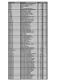
Brake Pads<br />
INTRODUCTION<br />
AP Racing’s Competition and High<br />
Performance Brake systems have been<br />
developed with the benefi t of our<br />
unparalleled experience in racing and<br />
performance brake technology to respond<br />
to the severe demands encountered<br />
under competitive and road conditions.<br />
The friction material used in a brake<br />
system is a vital factor in the overall<br />
performance of that system and it is<br />
therefore important to choose the correct<br />
pad for the particular application. As a<br />
major manufacturer of brake systems for<br />
competition and high performance vehicles,<br />
AP Racing is in an unique position<br />
to evaluate brake pad performance both<br />
on its own dynamometer test beds and<br />
on vehicles. AP Racing policy is to offer a<br />
range of the best friction materials currently<br />
available from whatever source.<br />
GENERAL<br />
INFORMATION.<br />
Pages 58 to 61 provide details on the<br />
range of pads and friction materials for<br />
competition and road use when using<br />
AP Racing brake calipers. This section<br />
also includes information to assist in the<br />
selection of the most suitable pad for a<br />
given application:-<br />
- Temperature ranges and measurement.<br />
- Advice on Brake noise.<br />
- Bedding in’ procedures.<br />
- Correct pad shape for a given<br />
AP Racing caliper.<br />
- Friction material choice.<br />
AP Racing Technical Section will be<br />
pleased to advise on the most suitable<br />
equipment for any particular application<br />
and can provide more detailed technical<br />
information if required.<br />
(For part numbering / ordering details<br />
please refer to page 61 .)<br />
PAD CHARACTERISTICS<br />
This section is intended to assist in the<br />
selection of the most suitable friction<br />
material for your application. There are<br />
numerous characteristics associated with<br />
friction materials, few of which are absolute,<br />
for example the friction Coeffi cient<br />
(μ) varies depending on temperature,<br />
speed, pressure and energy level and no<br />
two dynamometer programmes will ever<br />
produce quite the same results. Choosing<br />
the most suitable pad for your application<br />
is a complex problem requiring careful<br />
evaluation of all the available information.<br />
To help you with this AP Racing have<br />
developed a rating system for the principal<br />
pad characteristics incorporating both<br />
the experience gathered by our<br />
engineers over many years and our<br />
special dynamometer evaluation carried<br />
out in-house on our state of the art facility.<br />
The AP Racing dynamometer brake pad<br />
evaluation is based around a series of<br />
14 stops which represent the full range<br />
of conditions likely to be experienced in<br />
use. A composite dynamometer plot and<br />
an explanation of the AP Racing<br />
evaluation and rating systems is given<br />
below and on the page opposite.<br />
COMPOSITE<br />
DYNAMOMETER PLOT.<br />
This material<br />
shows relatively<br />
poor friction<br />
from cold<br />
improving as the<br />
pad heats up.<br />
AVERAGE FRICTION.<br />
Overall mean friction coefficient<br />
calculated over the complete test cycle.<br />
“BITE”.<br />
Initial friction at the start of the stop. Rating<br />
1 to 5. (5 = Good, 1 = Poor)<br />
FADE.<br />
Drop off in friction coeffi cient from stop<br />
to stop when used for very hard braking.<br />
Calculated from last 4 stops on test plot on<br />
a scale of 1 to 5. (5 = No signifi cant fade)<br />
AVERAGE PAD WEAR.<br />
A comparative rating of pad wear across<br />
all conditions. Rated on a scale<br />
PLOT SHAPE<br />
The shape of the friction plot during a<br />
brake application. High initial “bite” with<br />
friction gradually decreasing through the<br />
stop as speed drops off is considered<br />
to be the easiest to control (most “user<br />
friendly”). A climbing friction level through<br />
General Information<br />
1 2 3 4 5 6 7 8 9 10 11 12 13 14<br />
The Stop No.<br />
Very severe high<br />
speed stop from cold.<br />
(Cold Performance)<br />
This material has a<br />
good friction level but a<br />
climbing (non user friendly)<br />
plot and poor initial bite<br />
relative to the average<br />
friction level.<br />
Variety of stops<br />
ranging in severity<br />
from light to very<br />
severe.<br />
the stop is considered the most diffi cult<br />
to control (least “user friendly”) although<br />
some pads with this characteristic are<br />
extremely popular due to their overall<br />
high friction level and fade resistance.<br />
Rated on a comparative scale of 5 to 1.<br />
High initial “bite”<br />
with friction<br />
graduallyreducing<br />
& stabilising<br />
through the<br />
stop. Most<br />
“user friendly”.<br />
Rating 5<br />
COMFORT / NOISE<br />
Does the pad promote judder or brake<br />
squeal ?. Important on road car applications<br />
but not usually a consideration for<br />
This material<br />
exhibits slight<br />
fade but still<br />
maintains a<br />
relatively high<br />
friction level.<br />
Very severe stops<br />
from high speed to<br />
demonstrate fade<br />
capabilities.<br />
Essentially flat<br />
plot.<br />
Rating 3.<br />
www.apracing.com +44 (0)24 7663 9595<br />
Steeply rising<br />
plot.<br />
Least “user<br />
Friendly”.<br />
Rating 1.<br />
racing use. Rated<br />
subjectively on a<br />
scale from 1 to 5 ( 5<br />
= no noise / judder).<br />
DISC LIFE<br />
Does the pad<br />
promote high disc<br />
wear or cracking ?.<br />
Especially important<br />
on road car applications.<br />
Rated on a<br />
scale of 1 to 5<br />
( 5 = best).<br />
EFFECTIVE<br />
TEMPERATURE<br />
RANGE<br />
The temperature<br />
range within which<br />
the pad material<br />
can be considered<br />
effective should be<br />
used as a comparative guide only as<br />
temperature measurement techniques<br />
vary signifi cantly and the true picture<br />
must include the energy level (quantity of<br />
heat). Pad temperatures are affected by<br />
disc mass and cooling. Rated 1 to 5 (1 =<br />
200°C, 2 = 350°C, 3 = 500°C, 4 = 650°C<br />
and 5 = 800°C).<br />
SUITABLE AREA OF USE<br />
The areas for which the pad material is<br />
considered most suitable.<br />
This is a subjective assessment relying<br />
on the pooled experience of AP Racing<br />
engineers over many years. Contact AP<br />
Racing Technical Section for guidance.<br />
PAD MATERIAL PERFORMANCE<br />
The table overleaf provides the ratings<br />
given for the characteristics described<br />
on the this page. The table results are<br />
AP Racing’s own, determined from our<br />
dynamometer testing and may differ from<br />
manufacturers own specifi cations.
Pad<br />
Mat’l.<br />
General Information<br />
Ave<br />
Friction<br />
Mu.<br />
Performance Characteristics. Wear.<br />
Bite. Fade.<br />
Plot<br />
Shape.<br />
Comfort<br />
/ Noise.<br />
Disc<br />
Life.<br />
Ave<br />
Wear.<br />
Temp<br />
Range.<br />
Temp<br />
Rating.<br />
AP Racing Pad Materials.<br />
APF101 0.49 4 5 4 3 3 5 5<br />
APF102 0.39 5 3 5 3 3 4 4<br />
APF103 0.47 4 4 4 3 3 3 4<br />
Hawk Pad Materials.<br />
HT10 0.36 2 2 3 2 1 1 5<br />
HT14 0.35 4 4 4 3 3 3 3<br />
Ferodo Pad Materials.<br />
4003F 0.43 3 3 4 4 2 3 2<br />
3432F 0.39 3 3 2 4 1 3 3<br />
DS2500 0.34 3 3 4 5 4 3 2<br />
DS3000 0.42 2 2 4 3 3 3 4<br />
DS3000+ 0.41 3 3 3 3 4 2 4<br />
DS3000E 0.37 3 3 3 3 4 4 4<br />
DS1.11 0.43 2 3 1 3 4 4 4<br />
Mintex Pad Materials.<br />
F1R 0.46 4 4 3 3 4 4 4<br />
F2R 0.42 4 4 3 3 4 4 4<br />
F4R 0.47 4 4 3 3 4 4 3<br />
M1166 0.38 3 3 3 2 3 3 3<br />
Pagid Pad Materials.<br />
RS14 0.39 3 4 3 4 5 4 3<br />
RS4-2 0.35 4 2 4 3 4 4 3<br />
RS421 0.29 3 3 5 4 5 4 2<br />
Raybestos Pad Materials.<br />
ST39 0.40 2 2 2 3 3 2 2<br />
ST41 0.42 5 3 4 3 4 4 4<br />
ST42 0.37 5 4 4 3 3 4 4<br />
ST43 0.39 5 3 5 3 3 4 4<br />
Other Friction Materials.<br />
RQ3 0.41 3 5 3 5 4 3 2<br />
APH420 0.39 3 5 3 5 4 4 2<br />
SRR 0.46 5 4 5 5 4 1 3<br />
BRAKE PAD<br />
TEMPERATURES<br />
An important factor in consistent brake<br />
performance is maintaining the operating<br />
temperatures within the effective range<br />
of the pad material being used by<br />
controlling the fl ow of cooling air from the<br />
brake ducts. There are several different<br />
methods of monitoring the brake system<br />
temperatures:-<br />
1. THERMAL PAINTS<br />
2. BRAKE TEMPERATURE PYROMETER<br />
3. TEMPERATURE STRIPS<br />
For more detailed information of these<br />
methods please go to page 53.<br />
‘BEDDING IN’ PROCEDURES<br />
RACE FRICTION MATERIALS<br />
AP Racing offer a large variety of the best<br />
friction materials currently available from<br />
various sources to suit every racing<br />
condition. It is therefore very diffi cult to<br />
recommend a common ‘Bedding in’ procedures<br />
suitable for all friction materials.<br />
Please refer to the manufacturers own<br />
‘Bedding’ information for guidance.<br />
ROAD FRICTION MATERIALS<br />
For Pads for AP Racing brake calipers<br />
or kits use the following procedure:- Bed<br />
the pad and disc contact areas by using<br />
moderate brake applications for 80Km<br />
(50 miles), avoiding excessive speeds,<br />
building the stopping power and vehicle<br />
speed gradually over the next 80Km (50<br />
miles). This will ensure maximum pad<br />
performance and disc life.<br />
FOR AN OE PAD PLEASE REFER TO<br />
Light<br />
Comp.<br />
THE MANUFACTURERS OWN<br />
INSTRUCTIONS.<br />
F3 /<br />
(T.Car<br />
Rear).<br />
Brake Pads<br />
Suitable For.<br />
www.apracing.com +44 (0)24 7663 9595<br />
T.Car<br />
Front.<br />
BRAKE NOISE<br />
Brake noise or squeal is a vehicle system<br />
problem since the severity, regularity<br />
and tone is a function of the brake and<br />
suspension components in combination.<br />
This does not represent a problem on<br />
competition vehicles where performance<br />
is the primary objective but is generally<br />
unacceptable for road use. Some vehicles<br />
are particularly susceptible to the problem.<br />
The contact between the pad and disc<br />
during braking creates the raw energy to<br />
produce the noise but the actual squeal<br />
can be primarily or a combination of<br />
the disc, caliper and pad. Elimination of<br />
squeal under all brake operating conditions<br />
is diffi cult to achieve when specifying<br />
a brake package whose purpose is to<br />
safely absorb very high energy inputs.<br />
A number of methods are available to<br />
reduce the noise factor of a brake system<br />
but assuming the base vehicle suspension<br />
system is settled, the reduction or<br />
elimination of noise is usually achieved<br />
by a process of trial and error. The fi rst<br />
and easiest solution to try is the addition<br />
of high temperature grease to the back<br />
of the pad to provide a damping medium<br />
between the piston and pad.<br />
Typically Copper Slip is applied although<br />
care must be taken to avoid any grease<br />
coming into contact with the pad face.<br />
The use of high friction brake pads such<br />
as Pagid RS4-2 / M1177 creates high<br />
energy at the friction interface which<br />
can characteristically lead to more brake<br />
squeal but some pads are typical for<br />
their lower noise rating. These pads are<br />
characterised by their lower friction<br />
Sports<br />
Car.<br />
Rally.<br />
Grp<br />
‘N’<br />
Hill<br />
Climb.<br />
Road. Motor<br />
Cycle.<br />
coeffi cient and reduced initial ‘bite’.<br />
Examples of such a materials is Ferodo<br />
3432F. There are a number of disc<br />
variants available from AP Racing and<br />
the type chosen can have an effect on<br />
brake noise, depending again on the<br />
pad choice. Generally it is found the multi<br />
drilled or grooved discs used in conjunction<br />
with competition pads will give unacceptable<br />
noise levels for road use, Plain<br />
face discs can cause higher levels of<br />
squeal, as the pad is not cleaned by the<br />
actions of holes or grooves. For the AP<br />
Racing Formula Big Brake it conversions,<br />
we have found a reduced drill pattern<br />
with a radiused edge and using Ferodo<br />
DS2500 pads give little or no pad noise<br />
and still have good performance. Where<br />
the noise is a function of the brake pad<br />
temperature, characterised by the noise<br />
reducing (possibly to zero) as the brakes<br />
are used more severely. The pad may<br />
also respond to the addition of pad<br />
chamfers which reduce the effective pad<br />
area and change the pad shape / centre of<br />
pressure. These chamfers (10,0mm x 30<br />
degrees) can be added to the leading<br />
edge fi rst and their effect assessed prior<br />
to the addition of a chamfer on the trailing<br />
edge. Please contact AP Racing technical<br />
section for details of availability and<br />
specifi c requirements.<br />
ANTI-SQUEAL SHIMS<br />
Anti squeal shims are very effective and<br />
CP5070 pad family have them fi tted as<br />
standard. Anti squeal shims are also<br />
available for other pad families, but if you<br />
experience noise using other pad<br />
families please contact the road car<br />
technical section for further advice<br />
59
60<br />
Brake Pads<br />
Pads to suit AP Racing Calipers<br />
BRAKE PADS TO SUIT AP RACING BRAKE CALIPERS<br />
The tables opposite provide details of the complete range of AP Racing brake calipers and the correct pad shape to suit each caliper<br />
in the range. As well as providing information on current calipers, the table also includes all the obsolete AP Racing calipers.<br />
(Calipers no longer in production or no longer available from AP Racing ), and gives the correct pad family number where still<br />
available. Please refer to the table on page 61 to ensure that the pad shape is still available. When using the chart the following<br />
points should be noted:-<br />
1. Some installations require the use of a ‘Scalloped’ version of the given pad family. In these cases the full area pad cannot be used.<br />
2. In most cases a thinner version of the original pad can be used as an alternative.<br />
3. A ‘Scalloped’ pad (smaller radial depth) can usually be used in place of the full area pad but may affect ultimate performance.<br />
NB Inclusion of a caliper in this list does not indicate availability.<br />
Caliper<br />
Family<br />
No.<br />
Pad<br />
Family<br />
No.<br />
CP2195 CP2195<br />
CP2270 CP2270<br />
CP2271 CP2270<br />
CP2279 CP2279<br />
CP2290 CP2279<br />
CP2340 CP2340<br />
CP2361 CP2340<br />
CP2372 CP2372<br />
CP2373 CP2372<br />
CP2382 CP2372<br />
CP2383 CP2372<br />
CP2384 CP2372<br />
CP2385 CP2340<br />
CP2399 CP2399<br />
CP2409 CP2279<br />
CP2425 CP2270<br />
CP2485 CP2399<br />
CP2505 CP2195<br />
CP2561 CP2554<br />
CP2562 CP2554<br />
CP2564 CP3714<br />
CP2570 CP2372<br />
CP2575 CP2270<br />
CP2576 CP2399<br />
CP2577 CP2399<br />
CP2578 CP2372<br />
CP2586 CP2399<br />
CP2587 CP2399<br />
CP2600 CP2195<br />
CP2601 CP2195<br />
CP2632 CP2887<br />
CP2636 CP2279<br />
CP2639 CP2279<br />
CP2645 CP2645<br />
CP2661 CP2340<br />
CP2667 CP2399<br />
CP2696 CP2195<br />
CP2698 CP2372<br />
CP2699 CP2372<br />
CP2702 CP2702<br />
CP2712 CP2712<br />
CP2735 CP2195<br />
CP2736 CP2702<br />
CP2749 CP2749<br />
CP2750 CP2749<br />
CP2751 CP2749<br />
CP2752 CP2749<br />
CP2755 CP2749<br />
CP2756 CP2749<br />
CP2757 CP2749<br />
CP2758 CP2749<br />
CP2770 CP2195<br />
CP2824 CP2340<br />
CP2830 CP2830<br />
CP2831 CP2270<br />
CP2832 CP2749<br />
CP2833 CP2479<br />
CP2843 CP2749<br />
CP2852 CP2399<br />
CP2854 CP2554<br />
CP2862 CP2399<br />
CP2868 CP2868<br />
CP2870 CP2870<br />
CP2876 CP2270<br />
CP2877 CP2279<br />
CP2879 CP2554<br />
CP2887 CP2340<br />
CP2888 CP2340<br />
CP2889 CP2279<br />
CP2890 CP2279<br />
CP2895 CP2399<br />
CP2910 CP2279<br />
CP2917 CP2279<br />
CP2918 CP2279<br />
CP2919 CP2399<br />
CP2935 CP2279<br />
CP2936 CP2279<br />
CP2937 CP2279<br />
CP2966 CP2195<br />
CP2986 CP2270<br />
CP2988 CP2340<br />
CP2998 CP2998<br />
CP2999 CP2998<br />
CP3000 CP2998<br />
CP3008 CP2270<br />
CP3009 CP2279<br />
Caliper<br />
Family<br />
No.<br />
Pad<br />
Family<br />
No.<br />
CP3025 CP2279<br />
CP3026 CP2279<br />
CP3044 CP2399<br />
CP3045 CP2372<br />
CP3048 CP2279<br />
CP3086 CP3085<br />
CP3088 CP3086<br />
CP3089 CP2279<br />
CP3090 CP2279<br />
CP3093 CP2279<br />
CP3094 CP2279<br />
CP3107 CP3107<br />
CP3118 CP2279<br />
CP3129 CP2340<br />
CP3138 CP2279<br />
CP3139 CP2279<br />
CP3140 CP2279<br />
CP3148 CP2340<br />
CP3160 CP2749<br />
CP3161 CP2749<br />
CP3162 CP2749<br />
CP3163 CP2749<br />
CP3166 CP2749<br />
CP3167 CP2749<br />
CP3170 CP2279<br />
CP3172 CP2279<br />
CP3176 CP2399<br />
CP3177 CP2399<br />
CP3178 CP2399<br />
CP3185 CP3086<br />
CP3186 CP3086<br />
CP3207 CP3207<br />
CP3208 CP2086<br />
CP3209 CP2279<br />
CP3216 CP3215<br />
CP3228 CP2340<br />
CP3239 CP2279<br />
CP3240 CP2279<br />
CP3245 CP2749<br />
CP3248 CP3248<br />
CP3249 CP2279<br />
CP3257 CP3215<br />
CP3259 CP2749<br />
CP3286 CP3215<br />
CP3288 CP3215<br />
CP3307 CP3215<br />
CP3312 CP3215<br />
CP3315 CP2279<br />
CP3317 CP2279<br />
CP3326 CP3215<br />
CP3338 CP2340<br />
CP3343 CP2279<br />
CP3344 CP2340<br />
CP3345 CP2340<br />
CP3348 CP2340<br />
CP3349 CP2340<br />
CP3355 CP2340<br />
CP3358 CP2340<br />
CP3359 CP2340<br />
CP3360 CP2749<br />
CP3364 CP2340<br />
CP3365 CP2279<br />
CP3368 CP2279<br />
CP3369 CP3086<br />
CP3375 CP2279<br />
CP3378 CP2340<br />
CP3379 CP2340<br />
CP3385 CP3086<br />
CP3386 CP3086<br />
CP3387 CP3714<br />
CP3390 CP2279<br />
CP3394 CP2279<br />
CP3395 CP2279<br />
CP3416 CP2279<br />
CP3417 CP2279<br />
CP3426 CP2279<br />
CP3428 CP2340<br />
CP3434 CP3215<br />
CP3435 CP3215<br />
CP3436 CP2340<br />
CP3438 CP2279<br />
CP3439 CP2279<br />
CP3440 CP3215<br />
CP3341 CP2279<br />
CP3446 CP2279<br />
CP3447 CP2279<br />
Caliper<br />
Family<br />
No.<br />
Pad<br />
Family<br />
No.<br />
CP3449 CP2340<br />
CP3455 CP2279<br />
CP3456 CP2340<br />
CP3459 CP2340<br />
CP3463 CP2279<br />
CP3465 CP2279<br />
CP3470 CP3215<br />
CP3471 CP2279<br />
CP3475 CP3215<br />
CP3477 CP2340<br />
CP3479 CP2340<br />
CP3480 CP2279<br />
CP3481 CP2340<br />
CP3482 CP2340<br />
CP3483 CP2279<br />
CP3484 CP2279<br />
CP3485 CP3086<br />
CP3488 CP2279<br />
CP3489 CP2279<br />
CP3490 CP2279<br />
CP3495 CP2279<br />
CP3496 CP2270<br />
CP3498 CP2279<br />
CP3525 CP2279<br />
CP3536 CP2340<br />
CP3545 CP2340<br />
CP3546 CP2279<br />
CP3548 CP3548<br />
CP3549 CP3549<br />
CP3552 CP2749<br />
CP3553 CP2279<br />
CP3554 CP3555<br />
CP3555 CP3558<br />
CP3556 CP2340<br />
CP3557 CP2279<br />
CP3564 CP2340<br />
CP3565 CP2340<br />
CP3566 CP2279<br />
CP3567 CP2340<br />
CP3569 CP3086<br />
CP3570 CP2340<br />
CP3577 CP2340<br />
CP3578 CP2279<br />
CP3579 CP2279<br />
CP3584 CP2279<br />
CP3585 CP2340<br />
CP3586 CP3086<br />
CP3587 CP2340<br />
CP3595 CP2279<br />
CP3596 CP3596<br />
CP3599 CP2340<br />
CP3601 CP6301<br />
CP3604 CP3714<br />
CP3605 CP3714<br />
CP3608 CP2279<br />
CP3609 CP2279<br />
CP3614 CP3714<br />
CP3615 CP3714<br />
CP3617 CP2399<br />
CP3618 CP2340<br />
CP3619 CP2340<br />
CP3620 CP3215<br />
CP3629 CP2195<br />
CP3634 CP2279<br />
CP3635 CP2279<br />
CP3636 CP2279<br />
CP3637 CP2340<br />
CP3638 CP2279<br />
CP3639 CP2279<br />
CP3645 CP2340<br />
CP3646 CP2279<br />
CP3647 CP2340<br />
CP3650 CP2279<br />
CP3666 CP3666<br />
CP3667 CP3666<br />
CP3668 CP3666<br />
CP3676 CP2399<br />
CP3677 CP2399<br />
CP3679 CP3679<br />
CP3685 CP2340<br />
CP3687 CP2372<br />
CP3688 CP3215<br />
CP3689 CP2279<br />
CP3694 CP2279<br />
CP3695 CP2279<br />
CP3696 CP2195<br />
Caliper<br />
Family<br />
No.<br />
Pad<br />
Family<br />
No.<br />
CP3697 CP3195<br />
CP3704 CP3714<br />
CP3705 CP3714<br />
CP3708 CP2279<br />
CP3714 CP3714<br />
CP3715 CP3714<br />
CP3720 CP3215<br />
CP3721 CP2279<br />
CP3725 CP2279<br />
CP3727 CP3215<br />
CP3733 CP3215<br />
CP3735 CP2340<br />
CP3736 CP2279<br />
CP3737 CP2340<br />
CP3738 CP2279<br />
CP3746 CP2702<br />
CP3750 CP3215<br />
CP3755 CP3554<br />
CP3760 CP2279<br />
CP3769 CP3086<br />
CP3779 CP2561<br />
CP3788 CP2279<br />
CP3789 CP2279<br />
CP3790 CP2279<br />
CP3796 CP3796<br />
CP3799 CP2279<br />
CP3800 CP3800<br />
CP3801 CP2279<br />
CP3804 CP3714<br />
CP3805 CP3714<br />
CP3809 CP2279<br />
CP3814 CP3714<br />
CP3815 CP3714<br />
CP3820 CP2279<br />
CP3825 CP3800<br />
CP3827 CP3800<br />
CP3830 CP3800<br />
CP3846 CP2340<br />
CP3855 CP3554<br />
CP3876 CP2399<br />
CP3879 CP2561<br />
CP3894 CP3894<br />
CP3895 CP3894<br />
CP3896 CP3894<br />
CP3897 CP3894<br />
CP3939 CP2279<br />
CP3969 CP3086<br />
CP3970 CP4970<br />
CP3974 CP4970<br />
CP3977 CP4970<br />
CP3980 CP6210<br />
CP3996 CP3596<br />
CP4020 CP3215<br />
CP4066 CP2340<br />
CP4068 CP2340<br />
CP4069 CP4070<br />
CP4090 CP3894<br />
CP4096 CP3894<br />
CP4097 CP3894<br />
CP4098 CP3894<br />
CP4100 CP2554<br />
CP4120 CP2399<br />
CP4130 CP4296<br />
CP4131 CP4296<br />
CP4132 CP4296<br />
CP4140 CP4140<br />
CP4144 CP3345<br />
CP4145 CP2340<br />
CP4152 CP2340<br />
CP4155 CP4154<br />
CP4156 CP4154<br />
CP4158 CP4154<br />
CP4166 CP4466<br />
CP4169 CP4466<br />
CP4176 CP4466<br />
CP4177 CP4466<br />
CP4190 CP3558<br />
CP4218 CP3558<br />
CP4219 CP3558<br />
CP4220 CP2554<br />
CP4226 CP4226<br />
CP4227 CP4226<br />
CP4230 CP4595<br />
CP4240 CP4240<br />
CP4259 CP4240<br />
CP4260 CP4240<br />
Caliper<br />
Family<br />
No.<br />
Pad<br />
Family<br />
No.<br />
CP4270 CP2270<br />
CP4279 CP2279<br />
CP4280 CP4240<br />
CP4288 CP4288<br />
CP4289 CP4288<br />
CP4296 CP4296<br />
CP4409 CP2279<br />
CP4466 CP4466<br />
CP4469 CP4466<br />
CP4477 CP4466<br />
CP4484 CP4484<br />
CP4485 CP4484<br />
CP4488 CP4488<br />
CP4554 CP3558<br />
CP4556 CP2340<br />
CP4558 CP2340<br />
CP4567 CP3345<br />
CP4575 CP3558<br />
CP4576 CP3558<br />
CP4577 CP3558<br />
CP4586 CP2399<br />
CP4595 CP4595<br />
CP4596 CP2399<br />
CP4597 CP2749<br />
CP4598 CP4595<br />
CP4599 CP4595<br />
CP4604 CP3714<br />
CP4605 CP3714<br />
CP4608 CP3558<br />
CP4611 CP3894<br />
CP4612 CP3894<br />
CP4614 CP3714<br />
CP4615 CP3714<br />
CP4620 CP3215<br />
CP4621 CP3558<br />
CP4624 CP3714<br />
CP4638 CP3696<br />
CP4648 CP2195<br />
CP4649 CP2195<br />
CP4666 CP3666<br />
CP4680 CP4860<br />
CP4689 CP3679<br />
CP4690 CP3215<br />
CP4695 CP3558<br />
CP4698 CP4595<br />
CP4699 CP4595<br />
CP4704 CP3714<br />
CP4705 CP3714<br />
CP4714 CP3714<br />
CP4715 CP3714<br />
CP4720 CP3797<br />
CP4725 CP3215<br />
CP4728 CP3558<br />
CP4751 PFC751<br />
CP4760 CP3797<br />
CP4761 PFC751<br />
CP4771 PFC751<br />
CP4781 PFC751<br />
CP4790 CP3714<br />
CP4795 CP3558<br />
CP4844 CP4844<br />
CP4848 CP4848<br />
CP4849 CP4848<br />
CP4879 CP2399<br />
CP4890 CP3215<br />
CP4894 CP3894<br />
CP4896 CP3215<br />
CP4909 CP3894<br />
CP4910 CP3894<br />
CP4915 CP3894<br />
CP4920 CP3894<br />
CP4921 CP3894<br />
CP4922 CP3894<br />
CP4930 CP3894<br />
CP4960 CP4240<br />
CP4970 CP4970<br />
CP4974 CP4970<br />
CP4979 CP4990<br />
CP4995 CP4990<br />
CP4996 CP3215<br />
CP5000 RANGE<br />
-10 / -13 CP3714<br />
-20 / -23 CP3215<br />
-30 / -33 CP3345<br />
-40 / -43 CP3215<br />
-50 / -53 CP3215<br />
Caliper<br />
Family<br />
No.<br />
Pad<br />
Family<br />
No.<br />
-56 / -59 CP3215<br />
-74 / -77 CP3215<br />
CP5006 CP3215<br />
CP5015 CP3714<br />
CP5016 CP3714<br />
CP5017 CP3714<br />
CP5018 CP3714<br />
CP5020 CP2399<br />
CP5030 CP4296<br />
CP5040 RANGE<br />
-2 / -5 CP3215<br />
-10 / -13 CP3345<br />
-20 / -23 CP3714<br />
-30 / -33 CP2279<br />
CP5045 CP5045<br />
CP5060 CP3894<br />
CP5070 CP5070<br />
CP5090 CP2279<br />
CP5100 CP3345<br />
CP5104 CP2340<br />
CP5108 CP3345<br />
CP5111 CP5111<br />
CP5116 CP5234<br />
CP5120 CP3345<br />
CP5130 CP2340<br />
CP5144 CP2340<br />
CP5145 CP2279<br />
CP5146 CP5070<br />
CP5147 CP2340<br />
CP5148 CP5148<br />
CP5200 CP3215<br />
CP5205 CP3215<br />
CP5209 CP3215<br />
CP5210 CP3894<br />
CP5211 CP2399<br />
CP5218 CP2399<br />
CP5230 CP5230<br />
CP5234 CP5234<br />
CP5235 CP5119<br />
CP5260 CP3558<br />
CP5266 CP5166<br />
CP5270 CP3558<br />
CP5300 CP2564<br />
CP5308 CP2564<br />
CP5310 CP2399<br />
CP5311 CP2399<br />
CP5320 CP6600<br />
CP5410 CPF735<br />
CP5510 CPF735<br />
CP5515 CPF735<br />
CP5555 CP3894<br />
CP5560 CP3894<br />
CP5566 CP4466<br />
CP5570 CP3894<br />
CP5575 CP5070<br />
CP5577 CP4466<br />
CP5580 CP3894<br />
CP5588 CP4466<br />
CP5589 CP3215<br />
CP6610 CPF735<br />
CP5611 CP3894<br />
CP5620 CP3215<br />
CP5630 CP3894<br />
CP5666 CP3666<br />
CP5689 CP3215<br />
CP5710 CPF735<br />
CP5751 CPF751<br />
CP5752 CPF751<br />
CP5760 CP5860<br />
CP5761 CPF751<br />
CP5771 CPF751<br />
CP5788 CP5788<br />
CP5789 CP5788<br />
CP5800 CP4595<br />
CP5805 CPF753<br />
CP5806 CPF753<br />
CP5810 CP4595<br />
CP5820 CP5820<br />
CP5828 CP6230<br />
CP5830 CP2279<br />
CP5835 CP2279<br />
CP5840 CP5840<br />
CP5842 CP5820<br />
CP5850 CP5850<br />
CP5860 CP4970<br />
CP5865 CP4970<br />
www.apracing.com +44 (0)24 7663 9595<br />
Caliper<br />
Family<br />
No.<br />
Pad<br />
Family<br />
No.<br />
CP5866 CP4970<br />
CP5870 CP4970<br />
CP5880 CP2279<br />
CP5890 CP4595<br />
CP5960 CP4970<br />
CP5970 CP4970<br />
CP5971 CP4970<br />
CP5990 CP5788<br />
CP6030 CP2340<br />
CP6040 CP4970<br />
CP6041 CP4970<br />
CP6042 CP4970<br />
CP6044 CP4970<br />
CP6050 CP6050<br />
CP6051 CP6050<br />
CP6055 CP4240<br />
CP6056 CP3558<br />
CP6060 CP6210<br />
CP6065 CP6210<br />
CP6070 CP6070<br />
CP6071 CP6070<br />
CP6075 CP6230<br />
CP6080 CP4970<br />
CP6086<br />
CP6210<br />
CP4970<br />
CP6087<br />
CP3558<br />
CP4240<br />
CP6088<br />
CP3558<br />
CP4240<br />
CP6096 CP4970<br />
CP6114 CP5119<br />
CP6119 CP5119<br />
CP6120 CP5119<br />
CP6121 CP5119<br />
CP6148 CP5148<br />
CP6220 CP6220<br />
CP6230 CP6230<br />
CP6234 CP5234<br />
CP6235 CP6235<br />
CP6240 CP6230<br />
CP6315 CP3894<br />
CP6320 CP3215<br />
CP6340 CP3215<br />
CP6350 CP6230<br />
CP6360 CP6210<br />
CP6361 CP6210<br />
CP6420 CP3215<br />
CP6508 CP6508<br />
CP6520 CP3215<br />
CP6560 CP3215<br />
CP6561 CP3345<br />
CP6562 CP3215<br />
CP6564 CP3215<br />
CP6600 CP6600<br />
CP6602 CP6600<br />
CP6605 CP6600<br />
CP6608 CP6600<br />
CP6609 CP6600<br />
CP6611 CP6600<br />
CP6688 CP6688<br />
CP6720 CP3215<br />
CP6730 CP3215<br />
CP6740 CP3215<br />
CP6751 CPF751<br />
CP6760 CP3345<br />
CP6761 CPF751<br />
CP7040 CP7040<br />
CP7041 CP7040<br />
CP7045 CP7040<br />
CP7060 CP7040<br />
CP7600 CP7600<br />
CP7601 CP7600<br />
CP7602 CP7600<br />
CP7603 CP7600<br />
CP7605 CP7600<br />
CP7606 CP7600<br />
CP7607 CP7600<br />
CP7609 CP7600<br />
CP7611 CP7600<br />
CP7751 CPF751<br />
CP7853 CP4488
Friction Material Availability<br />
FRICTION MATERIAL<br />
AVAILABILITY<br />
In order to get the best performance<br />
from your AP Racing Brake System,<br />
it is important to choose the<br />
friction material which best suits the<br />
particular application.<br />
AP Racing offer a large variety of<br />
the best friction materials currently<br />
available from various sources to<br />
suit every racing condition. The table<br />
on this page gives information on<br />
all the friction materials in the<br />
current range and their availability.<br />
PAD ORDERING<br />
1. Refer to caliper listing on the<br />
previous page to obtain the correct<br />
pad shape for a given caliper and<br />
check this against the pad shape<br />
illustrations on pages 62 to 65.<br />
2. Consult the table opposite and<br />
select the material from those<br />
available referring to the information<br />
on pages 58 to 61 if necessary.<br />
3. Example part number opposite.<br />
E.G. CP3894D54-RS42.<br />
This part number comprises 4<br />
pads<br />
(1 axle set).<br />
4. Construct part number as in the<br />
example below by adding the<br />
material suffi x to the basic pad<br />
shape family number.<br />
All pads with the following<br />
exceptions are sold in sets of 4.<br />
- CP4226, CP3086, CP4484,<br />
CP3386, CP2372, CP3666,<br />
CP4466 are in pairs<br />
(2 pads).<br />
NB. For Carbon/Carbon Pad<br />
Material please contact AP Racing.<br />
NB. Materials with the blackout<br />
segments are on phase out mode<br />
and once stocks have been<br />
exhausted will be made inactive<br />
EXAMPLE<br />
PAD PART NUMBER<br />
Pad Family<br />
Part Number<br />
- Defi nes Pad<br />
Shape & Thickness<br />
18.00mm (0.71”)<br />
Pad Radial<br />
Depth<br />
54.0mm<br />
CP3894 D54- RS42<br />
Pad Material RS42<br />
Friction<br />
Materials<br />
Brake Pads<br />
Friction Material Availability<br />
AP Racing Ferodo Hawk Mintex Pagid Raybestos Others<br />
APF 101<br />
APF 102<br />
APF 103<br />
4003F<br />
DS2500<br />
DS3000<br />
www.apracing.com +44 (0)24 7663 9595<br />
DS3000+<br />
DS1.11<br />
HT10<br />
CP2195D38 � � � � � � �<br />
CP2279D42 � � � �<br />
CP2279D50 � � � �<br />
CP2340D38 �<br />
CP2340D40 � �<br />
CP2340D43 � � � � � � �<br />
CP2340D51 � � � � �<br />
CP2372D52<br />
CP2399D43 � � � � � � � �<br />
CP2702D53 �<br />
CP2712D44 �<br />
CP2749D66 �<br />
CP2868D38 �<br />
CP3086D37 �<br />
CP3215D42 � � � � � � � � �<br />
CP3215D46 � � � � � � � � � �<br />
CP3215D50 � � � � � � � � � � � �<br />
CP3345D38 � � � �<br />
CP3345D44 � � � � � � � � � � �<br />
CP3345D46 �<br />
CP3558D46 � �<br />
CP3558D51 �<br />
CP3558D54 � � � � � �<br />
CP3666D22 �<br />
CP3696D36 �<br />
CP3714D54 � � �<br />
CP3894D46 � � � � �<br />
CP3894D51 � � � � � � � � � �<br />
CP3894D54 � � � � �<br />
CP4226D27 � �<br />
CP4296D36 �<br />
CP4296D43 �<br />
CP4296D46 � �<br />
CP4466D22 � � �<br />
CP4479D50 � � � �<br />
CP4484D34 � �<br />
CP4595D54 � � � � � �<br />
CP4848D46 � � � � �<br />
CP5070D51 � � �<br />
CP5119D50 � � � � �<br />
CP5148D46 � � � � � �<br />
CP5510D43 � � � �<br />
CP5788D48 � � � � �<br />
CP5805D45 � �<br />
CP5820D62 � � � � �<br />
CP5850D62 � � �<br />
CP6050D50 � �<br />
CP6070D43 � � �<br />
CP6070D49 � � � �<br />
CP6210D46 �<br />
CP6210D54 � � � � � �<br />
CP6230D54 � � � �<br />
CP6600D55 � � �<br />
CP6688D29 �<br />
CP7040D54 � �<br />
CP7040D61 � �<br />
CP7600D46 � � �<br />
NOTES<br />
M1166<br />
F1R<br />
F2R<br />
F4R<br />
RS14<br />
RS42<br />
RS421<br />
ST41<br />
ST42<br />
ST43<br />
RQ3<br />
APH420<br />
SRR<br />
61
62<br />
Brake Pads<br />
Pad Profi les<br />
BRAKE PAD PROFILES FOR AP RACING CALIPERS<br />
The following details provide basic information for each of the pad shapes in the range of brake pads currently available from<br />
AP Racing. Please note that drawings are not to scale.<br />
CP2195D38<br />
- Pad Thickness = 10.5mm (0.40”)<br />
- Pad Depth = 38.4mm (1.51”)<br />
- Pad Area = 22.4cm² (3.47in²)<br />
59.3<br />
(2.34”)<br />
CP2279D50<br />
- Pad Thickness = 20.4mm (0.80”)<br />
- Pad Depth = 50.3mm (1.98”)<br />
- Pad Area = 57.4cm² (8.89in²)<br />
132.27 (5.20”)<br />
51.1<br />
(2.02”)<br />
54.1<br />
(2.02”)<br />
CP2340D43<br />
- Pad Thickness = 15.9mm (0.63”)<br />
- Pad Depth = 43.1mm (1.70”)<br />
- Pad Area = 40.4cm² (6.26in²)<br />
CP2399D43<br />
- Pad Thickness = 14.3mm (0.56”)<br />
- Pad Depth = 43.0mm (1.69”)<br />
- Pad Area = 27.7cm² (4.29in²)<br />
CP2749D66<br />
- Pad Thickness = 25.0mm (0.98”)<br />
- Pad Depth = 65.5mm (2.58”)<br />
- Pad Area = 77.84cm² (12.06in²)<br />
CP2270D46<br />
- Pad Thickness = 16.6mm (0.65”)<br />
- Pad Depth = 46.0mm (1.81”)<br />
- Pad Area = 56.3cm² (8.27in²)<br />
126.7 (4.98”)<br />
CP2340D38<br />
- Pad Thickness = 15.9mm (0.63”)<br />
- Pad Depth = 38.0mm (1.50”)<br />
- Pad Area = 37.1cm² (5.75in²)<br />
113.5 (4.47”)<br />
CP2340D51<br />
- Pad Thickness = 15.9mm (0.63”)<br />
- Pad Depth = 50.8mm (2.0”)<br />
- Pad Area = 43.4cm² (6.73in²)<br />
113.5 (4.47”) 113.5 (4.47”)<br />
70.1 (2.76”)<br />
130.0 (5.12”)<br />
58.1<br />
(2.28”)<br />
83.5<br />
(3.28”)<br />
47.0<br />
(1.85”)<br />
CP2702D53<br />
- Pad Thickness = 18.0mm (0.70”)<br />
- Pad Depth = 53.3mm (2.09”)<br />
- Pad Area = 49.55cm² (7.68in²)<br />
101.6 (4.0”)<br />
CP2868D38<br />
- Pad Thickness = 6.95mm (0.27”)<br />
- Pad Depth = 38.4mm (1.51”)<br />
- Pad Area = 22.4cm² (3.47in²)<br />
59.4 (2.34”)<br />
113.5 (4.47”)<br />
www.apracing.com +44 (0)24 7663 9595<br />
74.7<br />
(2.94”)<br />
54.4<br />
(2.14”)<br />
55.8<br />
(2.19”)<br />
43.0<br />
(1.69”)<br />
52.1<br />
(2.05”)<br />
CP2279D42<br />
- Pad Thickness = 20.4mm (0.80”)<br />
- Pad Depth = 42.0mm (1.65”)<br />
- Pad Area = 53.7cm² (8.38in²)<br />
132.27 (5.20)<br />
54.1<br />
(2.02”)<br />
CP2340D40<br />
- Pad Thickness = 15.9mm (0.63”)<br />
- Pad Depth = 40.0mm (1.57”)<br />
- Pad Area = 38.5cm² (5.96in²)<br />
45.4<br />
(1.78”)<br />
CP2372D52<br />
- Pad Thickness = 15.9mm (0.63”)<br />
- Pad Depth = 52.3mm (2.06”)<br />
- Pad Area = 34.61cm² (5.36in²)<br />
76.3 (3.00”)<br />
66.0<br />
(2.60”)<br />
CP2712D44<br />
- Pad Thickness = 14.8mm (0.58”)<br />
- Pad Depth = 43.5mm (1.71”)<br />
- Pad Area = 25.39cm² (3.93in²)<br />
83.8 (3.30”)<br />
55.0<br />
(2.16”)<br />
CP3086D37<br />
- Pad Thickness = 8.0mm (0.31”)<br />
- Pad Depth = 37.0mm (1.45”)<br />
- Pad Area = 26.13cm² (4.05in²)<br />
81.65 (3.21”)<br />
53.2<br />
(2.09”)
Pad Profi les<br />
Brake Pads<br />
BRAKE PAD PROFILES FOR AP RACING CALIPERS<br />
The following details provide basic information for each of the pad shapes in the range of brake pads currently available from<br />
AP Racing. Please note that drawings are not to scale.<br />
CP3215D42<br />
- Pad Thickness = 16.75mm (0.66”)<br />
- Pad Depth = 42.2mm (1.66”)<br />
- Pad Area = 51.9cm² (8.04in²)<br />
132.27 (5.20”)<br />
151.9 (5.98”)<br />
55.75<br />
(2.19”)<br />
CP3345D38<br />
- Pad Thickness = 15.9mm (0.66”)<br />
- Pad Depth = 38.0mm (1.49”)<br />
- Pad Area = 40.4cm² (6.26in²)<br />
113.47 (5.20”)<br />
52.1<br />
(2.05”)<br />
CP3558D51<br />
- Pad Thickness = 25.0mm (0.98”)<br />
- Pad Depth = 50.8mm (2.00”)<br />
- Pad Area = 73.7cm² (11.43in²)<br />
151.9 (5.98”)<br />
74.0<br />
(2.91”)<br />
CP3714D54<br />
- Pad Thickness = 25.0mm (0.98”)<br />
- Pad Depth = 54.0mm (2.12”)<br />
- Pad Area = 66.02cm² (10.23in²)<br />
130.0 (5.11”)<br />
76.3<br />
(3.00”)<br />
CP3894D54<br />
- Pad Thickness = 18.0mm (0.71”)<br />
- Pad Depth = 54.0mm (2.12”)<br />
- Pad Area = 77.44cm² (12.00in²)<br />
80.6<br />
(3.17”)<br />
CP3215D46<br />
- Pad Thickness = 16.75mm (0.66”)<br />
- Pad Depth = 45.67mm (1.79”)<br />
- Pad Area = 54.6cm² (8.45in²)<br />
132.27 (5.20”)<br />
113.47 (5.20”)<br />
151.9 (5.98”)<br />
www.apracing.com +44 (0)24 7663 9595<br />
55.75<br />
(2.19”)<br />
CP3345D44<br />
- Pad Thickness = 15.9mm (0.66”)<br />
- Pad Depth = 44.14mm (1.74”)<br />
- Pad Area = 43.47cm² (6.73in²)<br />
52.1<br />
(2.05”)<br />
CP3558D54<br />
- Pad Thickness = 25.0mm (0.98”)<br />
- Pad Depth = 54.0mm (2.12”)<br />
- Pad Area = 77.43cm² (12.00in²)<br />
151.9 (5.98”)<br />
80.6<br />
(3.17”)<br />
CP3894D46<br />
- Pad Thickness = 18.0mm (0.71”)<br />
- Pad Depth = 45.7mm (1.80”)<br />
- Pad Area = 66.6cm² (10.32in²)<br />
151.9 (5.98”)<br />
73.5<br />
(2.89”)<br />
CP4226D27<br />
- Pad Thickness = 7.0mm (0.27”)<br />
- Pad Depth = 26.84mm (1.05”)<br />
- Pad Area = 9.4cm² (1.45in²)<br />
39.7<br />
(1.56”)<br />
44.0<br />
(1.73”)<br />
CP3215D50<br />
- Pad Thickness = 16.75mm (0.66”)<br />
- Pad Depth = 50.29mm (1.98”)<br />
- Pad Area = 57.36cm² (8.89in²)<br />
132.27 (5.20”)<br />
100.5 (3.95”)<br />
55.75<br />
(2.19”)<br />
CP3558D46<br />
- Pad Thickness = 25.0mm (0.98”)<br />
- Pad Depth = 45.7mm (1.80”)<br />
- Pad Area = 66.6cm² (10.32in²)<br />
80.6<br />
(3.17”)<br />
CP3666D22<br />
- Pad Thickness = 8.9mm (0.35”)<br />
- Pad Depth = 22.0mm (0.86”)<br />
- Pad Area = 19.83cm² (3.07in²)<br />
32.71<br />
(1.29”)<br />
CP3894D51<br />
- Pad Thickness = 18.0mm (0.71”)<br />
- Pad Depth = 50.8mm (2.00”)<br />
- Pad Area = 73.7cm² (11.43in²)<br />
151.9 (5.98”)<br />
80.6<br />
(3.17”)<br />
CP4296D43<br />
- Pad Thickness = 16.0mm (0.63”)<br />
- Pad Depth = 43.3mm (1.70”)<br />
- Pad Area = 35.9cm² (5.56in²)<br />
94.49 (3.72”)<br />
53.45<br />
(2.10”)<br />
63
64<br />
Brake Pads<br />
CP5148D46<br />
- Pad Thickness = 15.0mm (0.59”)<br />
- Pad Depth = 46.0mm (1.81”)<br />
- Pad Area = 35.5cm² (5.50in²)<br />
86.0 (3.38”)<br />
63.0<br />
(2.48”)<br />
CP5510D43<br />
- Pad Thickness = 20.0mm (0.78”)<br />
- Pad Depth = 43.0mm (1.69”)<br />
- Pad Area = 39.39cm² (6.10in²)<br />
Pad Profi les<br />
BRAKE PAD PROFILES FOR AP RACING CALIPERS<br />
The following details provide basic information for each of the pad shapes in the range of brake pads currently available from<br />
AP Racing. Please note that drawings are not to scale.<br />
CP4296D46<br />
- Pad Thickness = 16.0mm (0.63”)<br />
- Pad Depth = 45.7mm (1.79”)<br />
- Pad Area = 36.9cm² (5.72in²)<br />
94.49 (3.72”)<br />
56.75<br />
(2.23”)<br />
CP4484D34<br />
- Pad Thickness = 8.0mm (0.31”)<br />
- Pad Depth = 34.0mm (1.34”)<br />
- Pad Area = 24.14cm² (3.74in²)<br />
76.32 (3.00”)<br />
46.20<br />
(1.81”)<br />
CP5045D61<br />
- Pad Thickness = 24.0mm (0.94”)<br />
- Pad Depth = 60.5mm (2.38”)<br />
- Pad Area = 74.0cm² (11.47in²)<br />
131.7 (5.18”)<br />
75.0<br />
(2.95”)<br />
CP5805D45<br />
- Pad Thickness = 19.8mm (0.77”)<br />
- Pad Depth = 45.0mm (1.77”)<br />
- Pad Area = 68.07cm² (10.55in²)<br />
151.9 (5.98”)<br />
64.26<br />
(2.52”)<br />
CP4466D22<br />
- Pad Thickness = 9.0mm (0.35”)<br />
- Pad Depth = 22.0mm (0.86”)<br />
- Pad Area = 19.83cm² (3.07in²)<br />
100.48 (3.95”)<br />
CP4479D50<br />
- Pad Thickness = 25.0mm (0.31”)<br />
- Pad Depth = 50.3mm (1.98”)<br />
- Pad Area = 60.44cm² (9.36in²)<br />
www.apracing.com +44 (0)24 7663 9595<br />
35.75<br />
(1.40”)<br />
CP4595D54<br />
- Pad Thickness = 28.5mm (1.12”)<br />
- Pad Depth = 54.0mm (2.12”)<br />
- Pad Area = 77.44cm² (12.00in²)<br />
151.9 (5.98”)<br />
80.6<br />
(3.17”)<br />
CP5070D51<br />
- Pad Thickness = 17.0mm (0.67”)<br />
- Pad Depth = 51.5mm (2.02”)<br />
- Pad Area = 77.2cm² (11.96in²)<br />
151.9 (5.98”)<br />
99.8 (3.92”)<br />
80.6<br />
(3.17”)<br />
45.5<br />
(1.79”)<br />
CP5820D62<br />
- Pad Thickness = 29.8mm (1.17”)<br />
- Pad Depth = 62.0mm (2.44”)<br />
- Pad Area = 89.84cm² (13.78in²)<br />
163.75 (6.44”)<br />
66.2<br />
(2.60”)<br />
131.3 (5.16”)<br />
55.75<br />
(2.19”)<br />
CP4848D46<br />
- Pad Thickness = 18.0mm (0.70”)<br />
- Pad Depth = 46.0mm (1.81”)<br />
- Pad Area = 35.5cm² (5.50in²)<br />
86.0 (3.38”)<br />
61.0<br />
(2.40”)<br />
CP5119D50<br />
- Pad Thickness = 14.35mm (0.56”)<br />
- Pad Depth = 50.0mm (1.96”)<br />
- Pad Area = 33.70m² (5.22in²)<br />
77.3<br />
(3.04”)<br />
68.15<br />
(2.68”)<br />
CP5788D48<br />
- Pad Thickness = 20.0mm (0.78”)<br />
- Pad Depth = 48.0mm (1.88”)<br />
- Pad Area = 63.2cm² (9.79in²)<br />
139.3 (5.48”)<br />
61.4<br />
(2.41”)<br />
CP5850D62<br />
- Pad Thickness = 27.7mm (1.09”)<br />
- Pad Depth = 62.0mm (2.44”)<br />
- Pad Area = 78.88cm² (12.22in²)<br />
139.2 (5.48”)<br />
70.5<br />
(2.77”)
Pad Profi les<br />
Brake Pads<br />
BRAKE PAD PROFILES FOR AP RACING CALIPERS<br />
The following details provide basic information for each of the pad shapes in the range of brake pads currently available from<br />
AP Racing. Please note that drawings are not to scale.<br />
CP6050D50<br />
- Pad Thickness = 20.0mm (0.78”)<br />
- Pad Depth = 50.0mm (1.96”)<br />
- Pad Area = 38.8cm² (6.01in²)<br />
86.0 (3.38”)<br />
67.0<br />
(2.63”)<br />
CP6230D54<br />
- Pad Thickness = 25.0mm (0.98”)<br />
- Pad Depth = 54.0mm (2.12”)<br />
- Pad Area = 81.62cm² (12.65in²)<br />
162.9 (6.41”)<br />
80.6<br />
(3.17”)<br />
CP7040D54<br />
- Pad Thickness = 16.75mm (0.66”)<br />
- Pad Depth = 54.0mm (2.12”)<br />
- Pad Area = 68.35cm² (10.59in²)<br />
CP7600D46<br />
- Pad Thickness = 16.0mm (0.63”)<br />
- Pad Depth = 46.2mm (1.81”)<br />
- Pad Area = 43.5cm² (6.74in²)<br />
NOTES<br />
149.0 (5.86”)<br />
113.48 (4.46”)<br />
81.75<br />
(3.21”)<br />
58.37<br />
(2.29”)<br />
CP6070D49<br />
- Pad Thickness = 25.0mm (0.98”)<br />
- Pad Depth = 49.0mm (1.92”)<br />
- Pad Area = 61.6cm² (9.54in²)<br />
131.6 (5.18”)<br />
CP6210D54<br />
- Pad Thickness = 30.0mm (1.18”)<br />
- Pad Depth = 54.0mm (2.12”)<br />
- Pad Area = 83.07cm² (12.97in²)<br />
www.apracing.com +44 (0)24 7663 9595<br />
59.0<br />
(2.32”)<br />
CP6600D55<br />
- Pad Thickness = 16.75mm (0.66”)<br />
- Pad Depth = 55.0mm (2.16”)<br />
- Pad Area = 64.6cm² (10.01in²)<br />
130.0 (5.11”)<br />
80.6<br />
(3.17”)<br />
CP7040D61<br />
- Pad Thickness = 16.75mm (0.66”)<br />
- Pad Depth = 61.0mm (2.40”)<br />
- Pad Area = 72.5cm² (11.23in²)<br />
149.0 (5.86”)<br />
85.75<br />
(3.37”)<br />
162.9 (6.41”)<br />
80.6<br />
(3.17”)<br />
CP6688D29<br />
- Pad Thickness = 10.0mm (0.39”)<br />
- Pad Depth = 28.5mm (1.12”)<br />
- Pad Area = 11.09cm² (1.71.in²)<br />
41.0<br />
(1.61”)<br />
28.5<br />
(1.12”)<br />
CP7600D43<br />
- Pad Thickness = 16.0mm (0.63”)<br />
- Pad Depth = 43.0mm (1.69”)<br />
- Pad Area = 42.2cm² (6.54in²)<br />
113.48 (4.46”)<br />
58.37<br />
(2.29”)<br />
65
66<br />
Actuation<br />
ACTUATION<br />
It is now widely understood that the<br />
actuation system is a major factor in the<br />
overall performance of the brake system.<br />
AP Racing R&D is now focused on this<br />
area and a number of new products have<br />
been added to the range which now<br />
includes not only Master Cylinders, Brake<br />
Fluid, Reservoirs, Proportioning Valves<br />
but also Floor Mounted and Underslung<br />
Pedal Boxes, Balance Bars, and<br />
accessories. This Section provides<br />
technical information regarding each<br />
product, if you require further details<br />
please contact AP Racing Technical Dept<br />
MASTER CYLINDERS<br />
AP Racing Master Cylinders have been<br />
developed with the benefi t of our unparalleled<br />
experience in racing brake technology<br />
to respond to the severe demands<br />
encountered under competition conditions<br />
and are used in motorsport from F1 to<br />
Rally to Saloon Cars. The Current range<br />
of lightweight aluminium alloy master<br />
cylinders comprises 8 designs suitable<br />
for all forms of competition use. Each<br />
master cylinder is individually shimmed<br />
during manufacture to give a shorter cut<br />
off and less lost travel than equivalent<br />
production cylinders and have 3 bypass<br />
ports for faster fl uid return. The standard<br />
short cut-off (0.68mm to 1.09mm / 0.027”<br />
to 0.043”) cylinders should be used for<br />
most normal applications and especially<br />
where rapid fl uid return when changing<br />
pads is required. Extra short cut-off<br />
(0.48mm to 0.63mm / 0.019” to 0.025”)<br />
cylinders are available in most styles and<br />
are identifi ed with an ‘E’ suffi x:<br />
e.g. CP2623-92PRT115E.<br />
Most designs are available in 10 bore<br />
sizes from 14mm to 25.4 (1.00”) diameter.<br />
Below and opposite is a brief description<br />
of each master cylinder within the range.<br />
MASTER CYLINDER RANGE<br />
CP2623 - A compact fl anged mounted<br />
Master Cylinder suitable for all brake and<br />
clutch applications<br />
especially where<br />
space is restricted.<br />
Short travel to cut<br />
off is standard,<br />
extra short cut-off also available. 10 bore<br />
sizes from 14.0mm to 25.4mm. Hydraulic<br />
threads are Imperial.<br />
CP4623 - A compact<br />
Master Cylinder<br />
similar to CP2623<br />
but with a 60°<br />
mounting fl ange offset to give improved<br />
access to mounting bolts. Short travel to<br />
cut-off is standard with extra short cut-off<br />
available to order. 10 bore sizes from<br />
14.0mm to 25.4mm. All threads on this<br />
master cylinder are metric.<br />
CP5623 - A compact<br />
Master Cylinder<br />
based on CP2623<br />
but with metric<br />
hydraulic ports. 9<br />
bore sizes from 14.0mm to 25.4mm.<br />
CP6093 - A Master<br />
Cylinder suitable<br />
for most brake and<br />
clutch applications<br />
where space restrictions are not a primary<br />
consideration. The longer available stroke<br />
makes it particularly suitable for some<br />
clutch installations. Long thread portion<br />
allows the push rod length to be cut to<br />
suit. 8 bore sizes from 15.9mm to 25.4mm<br />
Supercedes CP2293 Master Cylinder<br />
family<br />
CP4400 - A compact<br />
Master Cylinder<br />
which has been<br />
specially designed<br />
with a ‘centre lock’<br />
bulkhead fi xing (10mm Min. / 22mm Max.<br />
thick) to meet the installation requirements<br />
of composite structure racing cars. The<br />
inlet and the outlet ports are positioned<br />
at the end of the master cylinder away<br />
from the bulkhead, to provide clearance<br />
for steering racks etc., where required.<br />
Extra short travel to cut off, reducing the<br />
amount of lost pedal travel, is standard on<br />
this cylinder with short cut-off available to<br />
order where rapid fl uid return is required.<br />
9 bore sizes from 14.0mm to 15/16”.<br />
Hydraulic threads are imperial.<br />
CP5854 - A new<br />
high effi ciency<br />
single circuit, short<br />
push type master<br />
cylinder. Fixed<br />
through a trunnion system running in<br />
needle roller bearings and with a one<br />
piece piston / push rod it offers a signifi cant<br />
improvement in effi ciency over traditional<br />
master cylinder designs. Full range of 10<br />
bore sizes. Imperial threads.<br />
CP5855 - A new<br />
high effi ciency<br />
single circuit, short<br />
push type master<br />
cylinder. Fixed<br />
through a spherical bearing and with a<br />
one piece piston / push rod it offers a<br />
signifi cant improvement in effi ciency over<br />
Master Cylinders<br />
traditional master cylinder designs. Full<br />
range of 10 bore sizes. Imperial threads.<br />
Replaces CP5511 and CP4411.<br />
CP6465 - A new<br />
concept in Master<br />
Cylinder design.<br />
This cylinder<br />
operates on the<br />
Pull rather than<br />
Push principle of other cylinders. It has a<br />
built in trunnion mounted in needle roller<br />
bearings for direct mounting to the<br />
balance bar. The ultimate in master<br />
cylinder effi ciency. Metric threads.<br />
IMPORTANT NOTE:-<br />
AP Racing master cylinders are<br />
individually shimmed during assembly<br />
to minimise lost travel therefore<br />
push rods, pistons and other internal<br />
components must never be switched<br />
between individual master cylinders.<br />
ENDURANCE RACING<br />
In races where pad changes may be<br />
required short cut-off versions should<br />
be selected in preference to extra short<br />
cut-off. These assemblies allow fl uid to<br />
be forced back into the reservoir more<br />
rapidly during pad changes.<br />
NON CAPTIVE PUSH RODS<br />
Special versions of<br />
some master cylinders<br />
are available with ‘non<br />
captive’ push rods for<br />
use where rapid master<br />
cylinder changes may be required during<br />
an event (e.g. rally stages). Push rods<br />
to suit these master cylinders must be<br />
ordered separately under the following<br />
part numbers.<br />
Push Rod<br />
Part No.<br />
Length.<br />
Thread<br />
Form.<br />
Thread<br />
Length.<br />
CP2142-45 112.0mm 5/16” UNF 60.0mm<br />
CP2142-47 157.0mm 5/16” UNF 105.0mm<br />
CP2142-48 157.0mm M8x1.25 105.0mm<br />
IDENTIFICATION OF BORE<br />
SIZES.<br />
All AP Racing master<br />
cylinders have<br />
their part number,<br />
nominal bore sizes laser marked on the<br />
body together with batch codes, this<br />
allows full manufacturing traceability. All<br />
master cylinders also have a coloured tie<br />
wrapped around the body for quick visual<br />
identifi cation of bore size.<br />
14.0mm (0.551”) 0.55” Black & Orange.<br />
15.0mm (0.590”) 0.60” Black & Red.<br />
15.9mm (0.625”) 5/8” Black.<br />
16.8mm (0.661”) 0.66” Black & Yellow.<br />
17.8mm (0.70”) 0.7” Blue.<br />
19.1mm (0.75”) 3/4” Green.<br />
20.6mm (0.812”) 13/16” Orange.<br />
22.2mm (0.875”) 7/8” Red.<br />
23.8mm (0.937”) 15/16” White.<br />
25.4mm (1.00”) 1” Yellow.<br />
www.apracing.com +44 (0)24 7663 9595
Master Cylinders<br />
ORDERING<br />
When ordering please quote the full part number whenever<br />
possible. Part numbers are given in the individual master cylinder<br />
pages. An explanation of the part numbers is given below.<br />
Master Cylinder<br />
Family Number<br />
CP4623-90PRM160E<br />
Bore Size<br />
Ø15.9mm (5/8”)<br />
NB. For non captive push rod version add ’NC’ after bore size<br />
e.g. CP4623-90NCE<br />
MASTER CYLINDER REPAIR KITS<br />
CP2623, CP4400, CP4623, CP5623 and<br />
CP6093.<br />
Repair kit information for CP2623, CP4400, CP4623, CP5623<br />
and CP6093 are tabled below for all Master Cylinders sizes.<br />
Please follow the instructions below.<br />
INSTRUCTIONS<br />
1) Remove rubber boot (11) and circlip (10). 2) Carefully remove internal<br />
components. 3) Replace the following. (Making sure all seals have<br />
been lubricated with Brake Fluid). Primary seal (4), Piston Washer (5)<br />
and the Secondary seal (7).(Care must be taken when assembling<br />
seals as damage maybe caused) 4) Check bore is free from debris.<br />
5) Lubricate bore with Brake Fluid. 6) Reassemble internal components<br />
into body. 7) Use new circlip (10) to secure internal<br />
components and new boot to<br />
protect from debris (11).<br />
Ref. Description.<br />
Included<br />
in Repair<br />
Kit.<br />
Push Rod Thread<br />
Form (M8 x 1.25)<br />
Push Rod Length<br />
160mm (6.30”)<br />
Bore Size.<br />
‘E’ Denotes Short<br />
Cut-Off Version<br />
Repair Kit Part<br />
No.<br />
1. Body. 14.00mm CP2623-88RK<br />
2.<br />
Spring Guide<br />
Pin.<br />
15.00mm CP2623-89RK<br />
3.<br />
MCyl Return<br />
spring.<br />
15.9mm (0.625”) 5/8” CP2623-90RK<br />
4. Primary Seal. Yes. 16.8mm CP2623-905RK<br />
5. Piston Washer. Yes. 17.8mm (0.70”) CP2623-91RK<br />
6. Piston 19.1mm (0.75”) 3/4” CP2623-92RK<br />
7.<br />
Secondary<br />
Seal.<br />
Yes. 20.6mm (0.812”) 13/16” CP2623-93RK<br />
8. Push Rod. 22.2mm (0.875”) 7/8” CP2623-94RK<br />
9.<br />
Piston Stop<br />
Washer.<br />
23.8mm (0.937”) 15/16” CP2623-95RK<br />
10.<br />
11.<br />
Circlip.<br />
Boot.<br />
Yes.<br />
Yes.<br />
25.4mm (1.00”) CP2623-96RK<br />
CP5854 and CP5855.<br />
Repair kit information for CP5854 and CP5855 are tabled<br />
opposite for all Master Cylinders bore sizes. Please follow the<br />
instructions given.<br />
INSTRUCTIONS<br />
1) Remove rubber boot (11) and circlip (13). 2) Carefully remove internal<br />
components. 3) Replace the following. (Making sure all seals have<br />
been lubricated with Brake Fluid). Primary seal (1), Slydring Bearing<br />
(2), Piston Washer (4), O-Ring Piston Seal (5) & O-Ring End Cap Seal<br />
(9).(Care must be taken when assembling seals as damage may<br />
be caused). 4) Check bore is free from debris. 5) Lubricate bore with<br />
Brake Fluid. 6) Reassemble internal components into body. 7) Use new<br />
circlip (13) to secure internal components and new boot to protect from<br />
debris (11).<br />
Ref. Description.<br />
Master Cylinders<br />
Included<br />
in Repair<br />
Kit.<br />
Bore Size.<br />
www.apracing.com +44 (0)24 7663 9595<br />
Repair Kit<br />
Part No.<br />
1. Primary Seal. Yes. 14.00mm CP5854-88RK<br />
2.<br />
Slydring Bearing.<br />
Yes. 15.00mm CP5854-89RK<br />
3.<br />
MCyl Return<br />
Spring.<br />
15.9mm (0.625”) 5/8” CP5854-90RK<br />
4. Piston Washer. Yes. 16.8mm CP5854-905RK<br />
5.<br />
O-Ring<br />
Piston Seal.<br />
Yes. 17.8mm (0.70”) CP5854-91RK<br />
6.<br />
7.<br />
Cut-off Shim.<br />
Piston.<br />
19.1mm (0.75”) 3/4” CP5854-92RK<br />
8. End Cap.<br />
9.<br />
O-Ring Cap<br />
Seal.<br />
Yes.<br />
20.6mm (0.812”) 13/16” CP5854-93RK<br />
10.<br />
11.<br />
Lock Nut 5/16”<br />
UNF.<br />
Boot. Yes.<br />
22.2mm (0.875”)<br />
7/8”<br />
CP5854-94RK<br />
12.<br />
Spring Guide<br />
Pin.<br />
23.8mm (0.937”) 15/16” CP5854-95RK<br />
13.<br />
14.<br />
Circlip.<br />
Body.<br />
Yes.<br />
25.4mm (1.00”) CP5854-96RK<br />
CP6465.<br />
Repair kit information for CP6465 are tabled below for all<br />
Master Cylinders bore sizes. Please follow the instructions given.<br />
INSTRUCTIONS<br />
1) Remove rubber boot (12) and un screw end cap (9). 2) Carefully<br />
remove internal components. 3) Replace the following. (Making sure all<br />
seals have been lubricated with Brake Fluid). Primary seal (1), Slydring<br />
Bearing (2), Piston Washer (4), O-Ring Piston Seal (5) & O-Ring End<br />
Cap Seal (8).(Care must be taken when assembling seals as<br />
damage maybe caused) 4) Check bore is free from debris.<br />
5) Lubricate bore with Brake Fluid. 6) Reassemble internal components<br />
into body. 7) Use original end cap (9) to secure internal components.<br />
Tighten to 24Nm (18lbf-ft) and use loctite threadlocker 242 or 243).<br />
8) Fit new boot (12) to protect from debris.<br />
Ref. Description.<br />
Included<br />
in Repair<br />
Kit.<br />
Bore Size.<br />
Repair Kit Part<br />
No.<br />
1.<br />
Primary Cup<br />
Seal.<br />
Yes. 14.9mm CP6465-149RK<br />
2.<br />
Slydring<br />
Bearing.<br />
Yes. 16.2mm CP6465-162RK<br />
3.<br />
MCyl Return<br />
spring.<br />
17.3mm CP6465-173RK<br />
4. Piston Washer. Yes. 18.8mm CP6465-188RK<br />
5.<br />
O-Ring<br />
Piston Seal.<br />
Yes. 20.2mm CP6465-202RK<br />
6. Piston Stop. 21.8mm CP6465-218RK<br />
7. Piston. 23.7mm CP6465-237RK<br />
8. O-Ring Cap Seal. Yes. 25.4mm CP6465-254RK<br />
9. End Cap.<br />
10. Body.<br />
11. Locknut M8x1.25<br />
12. Boot.<br />
IMPORTANT NOTE<br />
The changing of internal components of the master cylinder in rare<br />
cases, may alter the distance to cut-off. If you are unable to bleed the<br />
cylinder after a seal change, please consult AP Racing. Also ensure<br />
that any parts that have been disassembled are kept with the original<br />
cylinder and are not mixed.<br />
67
68<br />
GENERAL INFORMATION<br />
- A compact Master Cylinder<br />
suitable for all brake and<br />
clutch applications especially<br />
where space is restricted.<br />
- Short travel to cut-off<br />
standard.<br />
- Aluminium alloy body.<br />
- Flange mounting.<br />
- Non captive cylinders<br />
available.<br />
- Extra short Cut-Off option<br />
available.<br />
- Replaces CP3823 Master<br />
Cylinder family.<br />
PART NUMBERS<br />
Actuation<br />
CP2623<br />
INSTALLATION DRAWING<br />
TECHNICAL DETAILS.<br />
Weight.<br />
0.31kg<br />
(0.7lbs)<br />
Full Stroke.<br />
25.4mm<br />
(1.00”)<br />
Travel To Cut-Off.<br />
- Short<br />
0.68 to 1.09mm<br />
(.027” to .043”)<br />
- Extra Short<br />
0.48 to 0.63mm<br />
(.019” to .025”)<br />
Hydraulic Thread.<br />
- Outlet. 3/8” x 24UNF<br />
- Inlet. 7/16” x 20UNF<br />
Push Rod Threads.<br />
- PRM M8 x 1.25<br />
- PRT 5/16” UNF<br />
Push Rod Length From<br />
Mounting Flange.<br />
PRM/PRT115 115mm (4.53”)<br />
PRM/PRT160 160mm (6.30”)<br />
Bore Sizes.<br />
Short Cut-off Cylinders.<br />
PRM<br />
PRT<br />
Pushrod.<br />
Pushrod.<br />
Non Captive<br />
Cylinders.<br />
14.0mm.<br />
CP2623-88PRM115<br />
CP2623-88PRM160<br />
CP2623-88PRT115<br />
CP2623-88PRT160<br />
CP2623-88NC<br />
15.0mm.<br />
CP2623-89PRM115<br />
CP2623-89PRM160<br />
CP2623-89PRT115<br />
CP2623-89PRT160<br />
CP2623-89NC<br />
15.9mm (.625”)<br />
5/8”<br />
CP2623-90PRM115<br />
CP2623-90PRM160<br />
CP2623-90PRT115<br />
CP2623-90PRT160<br />
CP2623-90NC<br />
16.8mm<br />
CP2623-905PRM115<br />
CP2623-905PRM160<br />
CP2623-905PRT115<br />
CP2623-905PRT160<br />
CP2623-905NC<br />
17.8<br />
(.70”)<br />
CP2623-91PRM115<br />
CP2623-91PRM160<br />
CP2623-91PRT115<br />
CP2623-91PRT160<br />
CP2623-91NC<br />
19.1mm (.75”)<br />
3/4”<br />
CP2623-92PRM115<br />
CP2623-92PRM160<br />
CP2623-92PRT115<br />
CP2623-92PRT160<br />
CP2623-92NC<br />
20.6mm (.812”)<br />
13/16”.<br />
CP2623-93PRM115<br />
CP2623-93PRM160<br />
CP2623-93PRT115<br />
CP2623-93PRT160<br />
CP2623-93NC<br />
22.2mm (.875”)<br />
7/8”.<br />
CP2623-94PRM115<br />
CP2623-94PRM160<br />
CP2623-94PRT115<br />
CP2623-94PRT160<br />
CP2623-94NC<br />
23.8mm (.937”)<br />
15/16”.<br />
CP2623-95PRM115<br />
CP2623-95PRM160<br />
CP2623-95PRT115<br />
CP2623-95PRT160<br />
CP2623-95NC<br />
25.4mm<br />
(1.00”).<br />
CP2623-96PRM115<br />
CP2623-96PRM160<br />
CP2623-96PRT115<br />
CP2623-96PRT160<br />
CP2623-96NC<br />
- Ordering -<br />
Select the required the required cylinder from the part numbers above.<br />
E.G. CP2623-94PRM115.<br />
- Extra Short Cut-Off Cylinder -<br />
For Extra short cut-off, add ‘E’ suffi x to the end of Part Number.<br />
E.G. CP2623-94PRT115E.<br />
Ø37.0<br />
R10.2<br />
28.58<br />
57.15<br />
2 HOLES<br />
Ø8.82<br />
8.70 THRO’<br />
28.5<br />
3/8” X 24UNF OUTLET<br />
AEROQUIP ADAPTOR<br />
AVAILABLE<br />
Ø30.0<br />
Ø17.8<br />
70.6<br />
36.6<br />
9.8<br />
80.0 MAX<br />
3.2<br />
45.00<br />
MIN THR’D DIM<br />
IMPORTANT<br />
FITTING OF NUT<br />
OR CLEVIS TO<br />
FULL EXTENT OF<br />
THREAD MAY<br />
RESTRICT PISTON<br />
TRAVEL.<br />
4.00°<br />
PUSHROD ANGULARITY<br />
NOT TO EXCEDD 4° INC<br />
BOOT SHOWN FULL<br />
EXTENDED ADJUST<br />
TO YOUR LIKING<br />
Ø32.98<br />
32.85<br />
Master Cylinders<br />
GENERAL INFORMATION<br />
- A compact Master Cylinder<br />
similar to CP2623 but with a<br />
60° mounting fl ange offset<br />
to give improved access to<br />
mounting bolts.<br />
- Extra short travel to cut off<br />
standard.<br />
- Short travel to cut-off<br />
optional.<br />
- Aluminium Alloy body.<br />
- 60° Flange mounting.<br />
- Non captive cylinders<br />
available.<br />
- All threads on this master<br />
cylinder are metric.<br />
PART NUMBERS<br />
CP4623<br />
INSTALLATION DRAWING<br />
TECHNICAL DETAILS.<br />
Weight.<br />
0.31kg<br />
(0.7lbs)<br />
Full Stroke.<br />
25.4mm<br />
(1.00”)<br />
Travel To Cut-Off.<br />
- Extra Short<br />
0.48 to 0.63mm<br />
(.019” to .025”)<br />
Hydraulic Thread.<br />
- Outlet. M10 x 1.0<br />
- Inlet. M12 x 1.0<br />
Push Rod Threads.<br />
- PRM M8 x 1.25<br />
- PRT 5/16” UNF<br />
Push Rod Length From<br />
Mounting Flange.<br />
PRM/PRT115 115mm (4.53”)<br />
PRM/PRT160 160mm (6.30”)<br />
Bore Sizes.<br />
Extra Short Cut-off Cylinders.<br />
PRM<br />
PRT<br />
Pushrod.<br />
Pushrod.<br />
Non Captive<br />
Cylinders.<br />
14.0mm.<br />
CP4623-88PRM115<br />
CP4623-88PRM160<br />
CP4623-88PRT115<br />
CP4623-88PRT160<br />
CP4623-88NC<br />
15.0mm.<br />
CP4623-89PRM115<br />
CP4623-89PRM160<br />
CP4623-89PRT115<br />
CP4623-89PRT160<br />
CP4623-89NC<br />
15.9mm (.625”)<br />
5/8”<br />
CP4623-90PRM115<br />
CP4623-90PRM160<br />
CP4623-90PRT115<br />
CP4623-90PRT160<br />
CP4623-90NC<br />
16.8mm<br />
CP4623-905PRM115<br />
CP4623-905PRM160<br />
CP4623-905PRT115<br />
CP4623-905PRT160<br />
CP4623-905NC<br />
17.8<br />
(.70”)<br />
CP4623-91PRM115<br />
CP4623-91PRM160<br />
CP4623-91PRT115<br />
CP4623-91PRT160<br />
CP4623-91NC<br />
19.1mm (.75”)<br />
3/4”<br />
CP4623-92PRM115<br />
CP4623-92PRM160<br />
CP4623-92PRT115<br />
CP4623-92PRT160<br />
CP4623-92NC<br />
20.6mm (.812”)<br />
13/16”.<br />
CP4623-93PRM115<br />
CP4623-93PRM160<br />
CP4623-93PRT115<br />
CP4623-93PRT160<br />
CP4623-93NC<br />
22.2mm (.875”)<br />
7/8”.<br />
CP4623-94PRM115<br />
CP4623-94PRM160<br />
CP4623-94PRT115<br />
CP4623-94PRT160<br />
CP4623-94NC<br />
23.8mm (.937”)<br />
15/16”.<br />
CP4623-95PRM115<br />
CP4623-95PRM160<br />
CP4623-95PRT115<br />
CP4623-95PRT160<br />
CP4623-95NC<br />
25.4mm<br />
(1.00”).<br />
CP4623-96PRM115<br />
CP4623-96PRM160<br />
CP4623-96PRT115<br />
CP4623-96PRT160<br />
CP4623-96NC<br />
- Ordering -<br />
Select the required the required cylinder from the part numbers above.<br />
E.G. CP4623-94PRM115E.<br />
- Short Cut-Off Cylinder Option -<br />
For Short cut-off, Remove ‘E’ suffi x from the end of Part Number.<br />
E.G. CP4623-94PRT115.<br />
www.apracing.com +44 (0)24 7663 9595<br />
1.62<br />
32.80<br />
52.20<br />
Ø37.00<br />
2 HOLES<br />
Ø8.76/8.64 THRU<br />
M10x1.0 OUTLET<br />
AEROQUIP ADAPTOR<br />
AVAILABLE<br />
57.15<br />
28.57<br />
17.80<br />
R10.16<br />
60°<br />
Ø30.0<br />
28.5<br />
70.54<br />
36.6<br />
PUSHROD<br />
ANGULARITY<br />
NOT TO EXCEED 4°<br />
9.77 PUSHROD<br />
LENGTH<br />
(SEE TECH SPECS)<br />
80.00 MAX 23.50<br />
MAX<br />
3.24<br />
4°<br />
33.02<br />
Ø32.89
GENERAL INFORMATION<br />
- A compact Master Cylinder<br />
identical to CP2623 but has<br />
metric hydraulic threads.<br />
Suitable for all brake and<br />
clutch applications especially<br />
where space is restricted.<br />
- Extra short travel to cut off<br />
standard.<br />
- Aluminium Alloy body.<br />
- Flange mounting.<br />
- Non captive cylinders<br />
available.<br />
PART NUMBERS<br />
Master Cylinders<br />
CP5623<br />
INSTALLATION DRAWING<br />
TECHNICAL DETAILS.<br />
0.3kg<br />
Weight.<br />
(0.66lbs)<br />
25.4mm<br />
Full Stroke.<br />
(1.00”)<br />
Travel To Cut-Off.<br />
0.48 to 0.63mm<br />
- Extra Short<br />
(.019” to .025”)<br />
Hydraulic Thread.<br />
- Outlet. M10 x 1.0<br />
- Inlet. M12 x 1.0<br />
Push Rod Threads.<br />
- PRM M8 x 1.25<br />
Push Rod Length From<br />
Mounting Flange.<br />
PRM115 115mm (4.53”)<br />
Bore Sizes.<br />
Extra Short Cut-off Cylinders.<br />
PRM<br />
Pushrod.<br />
Non Captive<br />
Cylinders.<br />
14.0mm. CP5623-88PRM115E CP5623-88NCE<br />
15.0mm. CP5623-89PRM115E CP5623-89NCE<br />
15.9mm (.625”)<br />
5/8”<br />
CP5623-90PRM115E CP5623-90NCE<br />
16.8mm CP5623-905PRM115E CP5623-905NCE<br />
17.8<br />
(.70”)<br />
CP5623-91PRM115E CP5623-91NCE<br />
19.1mm (.75”)<br />
3/4”<br />
CP5623-92PRM115E CP5623-92NCE<br />
20.6mm (.812”)<br />
13/16”.<br />
CP5623-93PRM115E CP5623-93NCE<br />
22.2mm (.875”)<br />
7/8”.<br />
CP5623-94PRM115E CP5623-94NCE<br />
23.8mm (.937”)<br />
15/16”.<br />
CP5623-95PRM115E CP5623-95NCE<br />
25.4mm<br />
(1.00”).<br />
CP5623-96PRM115E<br />
- Ordering -<br />
CP5623-96NEC<br />
Select the required the required cylinder from the part numbers above.<br />
E.G. CP5623-94PRM115E.<br />
50.40<br />
1.62<br />
31.00<br />
Ø37.0<br />
2 HOLES<br />
Ø8.76/8.64<br />
THRU<br />
28.58<br />
R10.16<br />
M10 x 1.0 OUTLET<br />
AEROQUIP ADAPTOR<br />
AVAILABLE<br />
57.15<br />
17.80<br />
28.5<br />
M12 x 1.0<br />
INLET<br />
Ø30.0<br />
70.54<br />
36.6<br />
9.77<br />
PUSHROD ANGULARITY<br />
NOT TO EXCEED 4°<br />
80.00 MAX 23.50 MAX<br />
3.00<br />
4°<br />
PUSHROD<br />
LENGTH (SEE TECH SPECS)<br />
33.02<br />
Ø32.89<br />
GENERAL INFORMATION<br />
- Flange mounted.<br />
- Full 31.75mm (1.25”) stroke<br />
across all bore sizes.<br />
- Replaces CP2293, more<br />
compact design with<br />
reduction in overall length.<br />
- Suitable for most brake &<br />
particularly clutch applications.<br />
- Short Travel to cut-off<br />
standard.<br />
- Aluminium Alloy body.<br />
PART NUMBERS<br />
Bore Sizes.<br />
15.9mm (.625”)<br />
5/8”<br />
Actuation<br />
CP6093<br />
PRT110<br />
Pushrod.<br />
INSTALLATION DRAWING<br />
TECHNICAL DETAILS.<br />
Weight.<br />
0.4kg<br />
(0.88lbs)<br />
Full Stroke.<br />
31.75mm<br />
(1.25”)<br />
Travel To Cut-Off.<br />
- Short<br />
0.68 to 1.09mm<br />
(.027” to .043”)<br />
Hydraulic Thread.<br />
- Outlet. 3/8” x 24UNF<br />
- Inlet. 7/16” x 20UNF<br />
Push Rod Threads.<br />
- PRT 5/16” UNF<br />
Push Rod Length From<br />
Mounting Flange.<br />
PRT110 110mm (4.33”)<br />
PRT155 155mm (6.10”)<br />
Short Cut-off Cylinders.<br />
PRT155<br />
Pushrod.<br />
CP6093-90PRT110 CP6093-90PRT155<br />
16.8mm CP6093-905PRT110 CP6093-905PRT155<br />
17.8<br />
(.70”)<br />
CP6093-91PRT110 CP6093-91PRT155<br />
19.1mm (.75”)<br />
3/4”<br />
CP6093-92PRT110 CP6093-92PRT155<br />
20.6mm (.812”)<br />
13/16”.<br />
CP6093-93PRT110 CP6093-93PRT155<br />
22.2mm (.875”)<br />
7/8”.<br />
CP6093-94PRT110 CP6093-94PRT155<br />
23.8mm (.937”)<br />
15/16”.<br />
CP6093-95PRT110 CP6093-95PRT155<br />
25.4mm<br />
(1.00”).<br />
CP6093-96PRT110<br />
- Ordering -<br />
CP6093-96PRT155<br />
Select the required bore size from the table above.<br />
E.G. CP6093-94PRT110.<br />
www.apracing.com +44 (0)24 7663 9595<br />
32.78<br />
Ø37.20<br />
MIN THR’D DIM’N - 35.0 FOR BORES 5/8” - 7/8”. - 37.0 FOR BORES15/16” - 1.0”<br />
2 HOLES<br />
Ø8.76/<br />
8.64 Ø17.80<br />
DIM’N ‘A’<br />
DIM’N ‘B’<br />
28.58<br />
R10.16<br />
57.15<br />
3/8” x 24UNF OUTLET<br />
AEROQUIP ADAPTOR<br />
AVAILABLE<br />
7/16” x 20UNF<br />
12.43<br />
Ø37.20<br />
DIM’N ‘C’<br />
DIM’N ‘D’<br />
DIM’N ‘F’ MAX<br />
VIEW SHOWING LARGER BOOT ON 15/16” & 1.0” CYLINDERS<br />
PUSHROD<br />
ANGULARITY<br />
NOT TO<br />
EXCEED 4°<br />
DIM’N ‘E’<br />
MAX<br />
32.97<br />
Ø32.84<br />
40.00<br />
MAX<br />
Bore Sizes.<br />
5/8” , 16.8mm,<br />
Dim’n<br />
‘A’<br />
Dim’n<br />
‘B’<br />
Dim’n<br />
‘C’<br />
Dim’n<br />
‘D’<br />
Dim’n<br />
‘E’<br />
Dim’n<br />
‘F’<br />
0.7”, 3/4”,<br />
13/16” & 7/8”<br />
109.06 49.26 28.5 11.81 20.2 118.33<br />
15/16” & 1.0” 107.28 47.48 30.8 10.03 21.55 116.18<br />
69
70<br />
GENERAL INFORMATION<br />
- Bulkhead mount.<br />
- A compact Master Cylinder<br />
which has been designed with<br />
a ‘centre lock’ bulkhead fi xing<br />
(10mm to 22mm Max) to meet<br />
the installation requirements<br />
of composite structure racing<br />
cars. The inlet and the outlet<br />
ports are positioned at the end<br />
of the master cylinder away<br />
from the bulkhead to provide<br />
clearance for steering racks<br />
etc, where required.<br />
- Aluminium Alloy body.<br />
- Extra short travel to cut-off<br />
standard.<br />
- New 15/16” bore size<br />
added.<br />
115.0<br />
PART NUMBERS<br />
Actuation<br />
CP4400<br />
INSTALLATION DRAWING<br />
TECHNICAL DETAILS.<br />
Weight.<br />
0.29kg<br />
(0.64lbs)<br />
Full Stroke.<br />
25.4mm<br />
(1.00”)<br />
Travel To Cut-Off.<br />
- Extra Short<br />
0.48 to 0.63mm<br />
(.019” to .025”)<br />
Hydraulic Thread.<br />
- Outlet. 3/8” x 24UNF<br />
- Inlet. 7/16” x 20UNF<br />
Push Rod Threads.<br />
- PRM M8 x 1.25<br />
- PRT 5/16” UNF<br />
Push Rod Length From<br />
Mounting Flange.<br />
PRM/PRT135 135mm (5.31”)<br />
PRM/PRT180 180mm (7.08”)<br />
Extra Short Cut-off Cylinders.<br />
Bore Sizes.<br />
PRT Pushrod. PRM Pushrod.<br />
14.0mm.<br />
CP4400-88PRT135E<br />
CP4400-88PRT180E<br />
CP4400-88PRM135E<br />
CP4400-88PRM180E<br />
15.0mm.<br />
CP4400-89PRT135E<br />
CP4400-89PRT180E<br />
CP4400-89PRM135E<br />
CP4400-89PRM180E<br />
15.9mm (.625”) CP4400-90PRT135E<br />
CP4400-90PRM135E<br />
5/8”<br />
CP4400-90PRT180E<br />
CP4400-90PRM180E<br />
16.8mm<br />
CP4400-905PRT135E<br />
CP4400-905PRT180E<br />
CP4400-905PRM135E<br />
CP4400-905PRM180E<br />
17.8<br />
CP4400-91PRT135E<br />
CP4400-91PRM135E<br />
(.70”)<br />
CP4400-91PRT180E<br />
CP4400-91PRM180E<br />
19.1mm (.75”) CP4400-92PRT135E<br />
CP4400-92PRM135E<br />
3/4”<br />
CP4400-92PRT180E<br />
CP4400-92PRM180E<br />
20.6mm (.812”) CP4400-93PRT135E<br />
CP4400-93PRM135E<br />
13/16”.<br />
CP4400-93PRT180E<br />
CP4400-93PRM180E<br />
22.2mm (.875”) CP4400-94PRT135E<br />
CP4400-94PRM135E<br />
7/8”.<br />
CP4400-94PRT180E<br />
CP4400-94PRM180E<br />
23.8mm (.937”) CP4400-95PRT135E<br />
CP4400-95PRM135E<br />
15/16”.<br />
CP4400-95PRT180E<br />
- Ordering -<br />
CP4400-95PRM180E<br />
Select the required the required cylinder from the part numbers above.<br />
E.G. CP4400-94PRM135E.<br />
Note: (1.00”) Bore size is not available in this cylinder series.<br />
89.00<br />
20.90<br />
0.375<br />
x 24UNF<br />
OUTLET<br />
‘THICK BULKHEAD’<br />
STEPPED LOCKING<br />
NUT VERSION<br />
61.37<br />
PUSHROD LENGTH<br />
10.0 MIN<br />
22.0 MAX<br />
BULKHEAD<br />
THICKNESS<br />
38.1 (1.5”) A.F. NUT<br />
Ø42.0 MAX O/D<br />
IMPORTANT:<br />
FITTING OF NUT<br />
OR CLEVIS TO<br />
73.5 MAX<br />
FULL EXTENT OF<br />
THR’D MAY<br />
RESULT IN RESTRICTED 67.00 46.0 MAX<br />
PISTON TRAVEL MIN THR’D DIM Ø32.00/31.90<br />
28<br />
42.0 MAX<br />
MAX BULKHEAD<br />
THICKNESS<br />
5.6<br />
m32x1-5-6g<br />
Ø34<br />
3.2<br />
3.0<br />
SLOT FOR<br />
RAD<br />
Ø3.0 PIN<br />
SECTION X-X<br />
20.0<br />
Master Cylinders<br />
GENERAL INFORMATION<br />
- Aluminium alloy body.<br />
- Compact design.<br />
- Hard anodised.<br />
-High effi ciency push type<br />
design.<br />
-One piece piston and push<br />
rod.<br />
- Has a built in trunnion<br />
mounted in needle roller<br />
bearing for direct mounting<br />
to the balance bar.<br />
- Use with CP5520-3, -4 or -13<br />
trunnion type balance bar or<br />
purpose designed pedal box.<br />
- Full range of 10 bore sizes.<br />
- Extra short travel to cut-off<br />
standard.<br />
- Rubber boots fi tted as<br />
standard.<br />
- Version with spherical<br />
bearing available under Part<br />
Number CP5855.<br />
PART NUMBERS<br />
Bore Sizes.<br />
CP5854<br />
Extra Short Cut-off<br />
Cylinders.<br />
INSTALLATION DRAWING<br />
TECHNICAL DETAILS.<br />
Weight.<br />
Full Stroke.<br />
14mm to 7/8”<br />
Bores<br />
15/16” to<br />
1.00” Bores<br />
www.apracing.com +44 (0)24 7663 9595<br />
0.28 to 0.293kg<br />
(0.61 to 0.64lbs)<br />
30.0mm (1.18”)<br />
28.0mm (1.10”)<br />
Travel To Cut-Off.<br />
0.48 to 0.63mm<br />
- Extra Short<br />
(.019” to .025”)<br />
Hydraulic Thread.<br />
- Outlet. 3/8” x 24UNF<br />
- Inlet. 7/16” x 20UNF<br />
Push Rod Threads.<br />
- PRTE 5/16” x 24 UNF<br />
Repair<br />
Kit.<br />
14.0mm. CP5854-88PRTE CP5854-88RK<br />
15.0mm. CP5854-89PRTE CP5854-89RK<br />
15.9mm (.625”)<br />
5/8”<br />
CP5854-90PRTE CP5854-90RK<br />
16.8mm CP5854-905PRTE CP5854-905RK<br />
17.8<br />
(.70”)<br />
CP5854-91PRTE CP5854-91RK<br />
19.1mm (.75”)<br />
3/4”<br />
CP5854-92PRTE CP5854-92RK<br />
20.6mm (.812”)<br />
13/16”.<br />
CP5854-93PRTE CP5854-93RK<br />
22.2mm (.875”)<br />
7/8”.<br />
CP5854-94PRTE CP5854-94RK<br />
23.8mm (.937”)<br />
15/16”.<br />
CP5854-95PRTE CP5854-95RK<br />
25.4mm<br />
(1.00”).<br />
CP5854-96PRTE<br />
- Ordering -<br />
CP5854-96RK<br />
Select the required bore size from the table above.<br />
E.G. CP5854-94PRTE.<br />
FLATS ARE INCLUDED ON PISTON TO HELP<br />
ASSEMBLE THE CYLINDER INTO A PEDAL BOX<br />
11.865<br />
11.835<br />
13.20<br />
28.10<br />
5/16”x24UNF<br />
THREAD<br />
30.00<br />
THREAD<br />
RUBBER BOOT IS INCLUDED<br />
FOR DEBRIS PROTECTION.<br />
39.00<br />
158.15<br />
THIS CYLINDER IS DESIGNED TO<br />
FIT DIRECT TO OUR RANGE OF<br />
RESERVOIR PORT<br />
7/16”X20UNF THREAD<br />
10.00 MIN DEPTH<br />
121.0 BOOT<br />
Ø ’A’<br />
56.00<br />
24.00<br />
10.13<br />
Dia ‘A’<br />
(mm)<br />
22.92<br />
on<br />
drawing<br />
29.25<br />
on<br />
drawing<br />
30.00<br />
Ø7.987 / 7.972<br />
REQUIRED<br />
SHAFT DIMN &<br />
SURFACE FINISH<br />
BALANCE BAR ASSEMBLIES 0.8<br />
EACH PART WILL BE<br />
LASER MARKED WITH<br />
SIZE, PART No. AND<br />
SERIAL No.<br />
OUTLET PORT<br />
3/8”X24UNF THREAD<br />
11.00 MIN DEPTH
GENERAL INFORMATION<br />
- Aluminium alloy body.<br />
- Compact design.<br />
- Hard anodised.<br />
- High effi ciency push type<br />
design.<br />
- Mounted through a spherical<br />
bearing.<br />
- One piece piston and push<br />
rod.<br />
- Full range of 10 bore sizes.<br />
- Extra short travel to cut-off<br />
standard.<br />
- Rubber boots fi tted as<br />
standard.<br />
- Version with built in trunnion<br />
mounting available under Part<br />
No. CP5854 Family.<br />
- Replaces CP5511 and<br />
CP4411 families.<br />
PART NUMBERS<br />
Bore Sizes.<br />
Master Cylinders<br />
CP5855<br />
Extra Short Cut-off<br />
Cylinders.<br />
INSTALLATION DRAWING<br />
TECHNICAL DETAILS.<br />
Weight.<br />
Full Stroke.<br />
14mm to 7/8”<br />
Bores<br />
15/16” to<br />
1.00” Bores<br />
0.28 to 0.293kg<br />
(0.61 to 0.64lbs)<br />
30.0mm (1.18”)<br />
28.0mm (1.10”)<br />
Travel To Cut-Off.<br />
0.48 to 0.63mm<br />
- Extra Short<br />
(.019” to .025”)<br />
Hydraulic Thread.<br />
- Outlet. 3/8” x 24UNF<br />
- Inlet. 7/16” x 20UNF<br />
Push Rod Threads.<br />
- PRTE 5/16” x 24 UNF<br />
Repair<br />
Kit.<br />
14.0mm. CP5855-88PRTE CP5854-88RK<br />
15.0mm. CP5855-89PRTE CP5854-89RK<br />
15.9mm (.625”)<br />
5/8”<br />
CP5855-90PRTE CP5854-90RK<br />
16.8mm CP5855-905PRTE CP5854-905RK<br />
17.8<br />
(.70”)<br />
CP5855-91PRTE CP5854-91RK<br />
19.1mm (.75”)<br />
3/4”<br />
CP5855-92PRTE CP5854-92RK<br />
20.6mm (.812”)<br />
13/16”.<br />
CP5855-93PRTE CP5854-93RK<br />
22.2mm (.875”)<br />
7/8”.<br />
CP5855-94PRTE CP5854-94RK<br />
23.8mm (.937”)<br />
15/16”.<br />
CP5855-95PRTE CP5854-95RK<br />
25.4mm<br />
(1.00”).<br />
CP5855-96PRTE<br />
- Ordering -<br />
CP5854-96RK<br />
Select the required bore size from the table above.<br />
E.G. CP5855-94PRTE.<br />
ASSEMBLE THECYLINDER INTO A PEDAL BOX<br />
155.65<br />
118.5 BOOT<br />
30.00<br />
THREAD<br />
28.10 FLATS ARE INCLUDED ON PISTON TO HELP<br />
39.00<br />
5/16”x24UNF<br />
THREAD<br />
RUBBER BOOT IS INCLUDED<br />
FOR DEBRIS PROTECTION.<br />
BOOT INCLUDED, AND SPARES<br />
ARE AVAILABLE.<br />
RESERVOIR PORT<br />
7/16”UNF THREAD,<br />
10.00 MIN DEPTH<br />
Ø ‘A’<br />
53.50<br />
21.50 12.50 MAX<br />
30.00<br />
Dia ‘A’<br />
(mm)<br />
22.92<br />
on<br />
drawing<br />
29.25<br />
on<br />
drawing<br />
SPHERICAL BEARING<br />
Ø6.35 (¼”) BORE<br />
Ø6.350/6.337<br />
EACH PART WILL BE<br />
LASER MARKED WITH<br />
SIZE, PART No. AND<br />
SERIAL No.<br />
11.10<br />
11.05<br />
OUTLET PORT<br />
3/8”UNF THREAD<br />
11.00 MIN DEPTH<br />
GENERAL INFORMATION<br />
- A new concept pull type<br />
design, more effi cient than<br />
conventional type master<br />
cylinders.<br />
- Aluminium Alloy Body.<br />
- Has a built in trunnion<br />
mounted in needle roller<br />
bearing for direct mounting to<br />
the balance bar.<br />
- Low profi le inlet and outlet.<br />
- Special “plug in” inlet<br />
connection can be swaged<br />
directly to dash 4 hose.<br />
- Use with CP5520-2 or<br />
CP5516-17 type<br />
trunnion type balance bar or<br />
purpose designed pedal box.<br />
- Choice of 8 bore sizes.<br />
- Extra short travel to cut-off<br />
standard.<br />
PART NUMBERS<br />
Actuation<br />
CP6465<br />
INSTALLATION DRAWING<br />
TECHNICAL DETAILS.<br />
0.23 to 0.27kg<br />
Weight.<br />
(0.51 to 0.59lbs)<br />
25.4mm<br />
Full Stroke.<br />
(1.00”)<br />
Travel To Cut-Off.<br />
0.48 to 0.63mm<br />
- Extra Short<br />
(.019” to .025”)<br />
Hydraulic Thread.<br />
- Outlet. M10 x 1.0<br />
Inlet, Special Fittings.<br />
75° type. CP6465-10<br />
Straight type. CP6465-11<br />
90° type. CP6465-12<br />
All inlet fi itings are sold<br />
separately.<br />
Push Rod Threads.<br />
- PRME M8 x 1.25<br />
Bore Sizes.<br />
Extra Short Cut-off Cylinders.<br />
PRME<br />
Pushrod.<br />
Repair Kits.<br />
14.9mm<br />
(.587”).<br />
CP6465-149PRME CP6465-149RK<br />
16.2mm<br />
(.368”).<br />
CP6465-162PRME CP6465-162RK<br />
17.3<br />
(.681”).<br />
CP6465-173PRME CP6465-173RK<br />
18.8mm<br />
(.740”).<br />
CP6465-188PRME CP6465-188RK<br />
20.2mm<br />
(.795”).<br />
CP6465-202PRME CP6465-202RK<br />
21.8mm<br />
(.858”)<br />
CP6465-218PRME CP6465-218RK<br />
23.7mm<br />
(.933”).<br />
CP6465-237PRME CP6465-237RK<br />
25.4mm<br />
(1.00”).<br />
CP6465-254PRME<br />
- Ordering -<br />
CP6465-254RK<br />
Select the required bore size from the table above.<br />
E.G. CP6465-237PRME.<br />
(NOT SOLD WITH CYLINDER)<br />
THIS FITTING IS DESIGNED TO<br />
THE GOODRIDGE G-LINE<br />
RANGE OF FITTINGS & HOSES.<br />
AP RACING RECOMMEND THE HEX HEAD BOLT<br />
910 SERIES HOSE<br />
M4x0.7 THREAD<br />
Ø7.987/7.972<br />
REQUIRED SHAFT DIM’N & SURFACE FINISH 0.8<br />
www.apracing.com +44 (0)24 7663 9595<br />
31.75<br />
A / F<br />
24.70<br />
12.50<br />
M8x1.25 THREAD<br />
59.80<br />
27.25<br />
RUBBER BOOT FOR<br />
DEBRIS PROTECTION<br />
85.10 TO CAP<br />
93.90 TO BOOT<br />
Ø14.0 MAX<br />
25.53<br />
MAX<br />
51.19 TO CAP STROKE<br />
42.39 TO BOOT<br />
OUTLET M10x1.0 THREAD<br />
8.00 MIN THREAD DEPTH<br />
15.00°<br />
23.50 18.15<br />
71
72<br />
GENERAL INFORMATION<br />
- Double ended hand brake<br />
Master Cylinder.<br />
- For use with dual circuits.<br />
- Where diagonal brake split<br />
is mandatory.<br />
- Forged Aluminium alloy<br />
body.<br />
- Lightweight compact design.<br />
- Hard anodised.<br />
- High effi ciency push type<br />
design.<br />
- Mounted using rod ended<br />
spherical bearings.<br />
- One piece piston and push<br />
rod.<br />
- Rubber boots fi tted<br />
as standard.<br />
Actuation<br />
CP6026<br />
PART NUMBERS & SPARES<br />
INSTALLATION DRAWING<br />
TECHNICAL DETAILS.<br />
Weight.<br />
0.25kg<br />
(0.55lbs)<br />
Full Stroke. 2 x 12mm<br />
Bore Dia. 0.70” (17.8mm)<br />
Travel To Cut-Off.<br />
- Extra Short<br />
0.48 to 0.63mm<br />
(.019” to .025”)<br />
Hydraulic Thread.<br />
- Outlet. M10 x 1.0<br />
- Inlet. M10 x 1.0<br />
Typical<br />
Application.<br />
Dual Circuit<br />
hand brake<br />
sytems.<br />
PART NUMBER = CP6026-91<br />
SPARES LIST<br />
AP RACING<br />
REF: DESCRIPTION<br />
PART No.<br />
QTY/<br />
CYL<br />
1 ROD END CP6026-101 2<br />
2 M6 NUT ME21001 2<br />
ADDITIONAL SPARE PARTS<br />
SEAL REPAIR KIT<br />
(2 OFF EACH<br />
-<br />
PART) BOOTS,<br />
SEALS, PISTON<br />
WASHERS &<br />
CIRCLIPS.<br />
CP6025-91RK -<br />
22.00<br />
9.00<br />
12.00 MIN<br />
STROKE<br />
EACH END<br />
Ø6.00<br />
Ø32.0 MAX<br />
25.9<br />
5.00°<br />
221.00 ±6.0<br />
5.00°<br />
8.06 8.06<br />
78.00<br />
53.00<br />
OUTLET<br />
PORTS<br />
INLET<br />
PORTS<br />
29.6<br />
New<br />
Product<br />
1<br />
2<br />
NOTES.<br />
Master Cylinders<br />
www.apracing.com +44 (0)24 7663 9595
Fluid Reservoirs Actuation<br />
INTRODUCTION<br />
AP Racing offer a comprehensive<br />
range of plastic reservoir to<br />
compliment not only are Master<br />
Cylinders but other manufacturers<br />
also.<br />
RESERVOIR RANGE<br />
CP4709 TYPE<br />
A small diameter plastic reservoir<br />
with central outlet which can be<br />
screwed directly into a master<br />
cylinder.<br />
- Available in a choice of 3 volumes.<br />
- ‘O’ Ring seal supplied.<br />
- CP2709-156 Bellows available.<br />
- Push on connector for remote<br />
cylinder available - CP4709-107.<br />
Part Numbers<br />
- CP4709-10,-11 & -12<br />
Will screw directly onto, CP2623,<br />
CP4623, CP5623 and CP6093<br />
cylinders by removing inlet adaptor.<br />
Note: For fi tting instructions refer<br />
to leafl et P14.073 on website.<br />
www.apracing.com/car/cylinder/<br />
fl uiddata.asp?code=cp4709dfi t.<br />
- CP4709-13,-14 & -15 are for<br />
remote use but will fi t directly to<br />
CP4400 master cylinders.<br />
- CP4709- 16 & -17.<br />
are for remote use only.<br />
O-RING SEAL<br />
SUPPLIED WITH<br />
ALL RESERVOIRS<br />
TO REMOVE CAP<br />
DIMN ‘L’ 12.0 MIN SPACE<br />
Ø51.00<br />
Ø44.00 ‘M’<br />
THREAD<br />
SIZE<br />
Part<br />
Number.<br />
Type.<br />
Volume<br />
CC’S<br />
Dim’n<br />
‘L’<br />
(mm)<br />
CP4709<br />
-10<br />
Tall 183.0 169.0<br />
CP4709<br />
-11<br />
Med 123.0 119.0<br />
CP4709<br />
-12<br />
Short 75.0 79.0<br />
CP4709<br />
-13<br />
Short 75.0 96.0<br />
CP4709<br />
-14<br />
Med 123.0 136.0<br />
CP4709<br />
-15<br />
Tall 183.0 186.0<br />
CP4709<br />
-16<br />
Short 75.0 96.0<br />
CP4709<br />
-17<br />
Med 123.0 136.0<br />
Thread<br />
Size<br />
15/16”<br />
x 20<br />
UNS<br />
7/16”<br />
x 20<br />
UNF<br />
M12<br />
x 1.0<br />
CP4773 TYPE<br />
CP4773-1 (7/16UNF outlet)<br />
and CP4773-2 (M12 outlet).<br />
The new reservoirs capacity<br />
are midway between,<br />
CP4709 and CP2293-141/3<br />
types. Both assemblies have<br />
an offset outlet and are fi tted<br />
with bellows (CP4773-102).<br />
Volume = 195cm³.<br />
CP2293-141 / -143 &<br />
CP4623-7 / -8 TYPES<br />
- A large capacity plastic reservoir with offset<br />
outlet which screws directly into the master<br />
cylinders detailed below.<br />
- Can be supplied with or<br />
without rubber diaphragm,<br />
(CP2293-48).<br />
- Supplied complete with cap<br />
4325-148 & adaptor.<br />
- CP2293-141 & -143<br />
suitable for: CP2623, CP4400,<br />
CP6093.<br />
- CP4623-7 & -8 suitable for:<br />
CP4623, CP5623.<br />
- To rotate reservoir unlock nut included and<br />
reposition, then re-tighten.<br />
CP2293-162 & -163<br />
- Two extra large capacity plastic reservoir with<br />
either offset or central outlets which screws<br />
directly into all master cylinders with 7/16” UNF<br />
inlet thread.<br />
- Volume = 340cm³ (20.7in³)<br />
- Supplied with CP2293-166 rubber diaphragm<br />
(Bellows) to minimise entry of moisture, dirt and<br />
help prevent spillage.<br />
- Supplied complete with cap 4325-148 & adaptor.<br />
CP2293-162<br />
CP2293-163<br />
112009<br />
- A remote plastic reservoir, accepts<br />
Ø5/16” hose.<br />
- Complete with steel<br />
mounting bracket and<br />
cap 3847-241<br />
- Volume = 185cm³<br />
(11.3in³)<br />
- No Diaphragm<br />
available.<br />
113.00<br />
100.40<br />
Ø63.25 MAX<br />
12 (0.47")<br />
Ø89 (3.50")<br />
Ø66 (2.60")<br />
Part No. Diaphragm.<br />
Volume cm³<br />
(in³).<br />
Fitting<br />
CP2293-141 No<br />
7/16” UNF<br />
CP4623-7 Yes 275<br />
M12x1.0<br />
CP2293-143 Yes (13.4) 7/16” UNF<br />
CP4623-8 No M12x1.0<br />
21.25<br />
Ø88.50<br />
Ø72.80<br />
19.50 22.00<br />
145.30<br />
7/16" UNF<br />
Ø1/4" UNC<br />
BOLT<br />
CP2293-69 & 4342-372<br />
- A large capacity<br />
remote plastic reservoir<br />
with 1 outlet.<br />
- CP2293-69 supplied<br />
with diaphragm<br />
(bellows).<br />
- 4342-372 supplied<br />
without diaphragm<br />
(bellows)<br />
- Accepts Ø5/16”<br />
diameter hose.<br />
- Volume = 280cm³<br />
(17.1in³).<br />
- Supplied complete<br />
with cap 4325-148.<br />
CP2293-85 & 4342-355<br />
- A large capacity<br />
remote plastic reservoir<br />
with 2 outlets.<br />
- CP2293-85 supplied<br />
with diaphragm<br />
(bellows).<br />
- 4342-355 supplied<br />
without diaphragm<br />
(bellows)<br />
- Accepts Ø5/16”<br />
diameter hose.<br />
- Volume = 280cm³<br />
(17.1in³)<br />
- Supplied complete with<br />
cap 4325-148.<br />
DIAPHRAGMS (BELLOWS)<br />
Rubber Diaphragms (bellows) minimise the<br />
entry of moisture and dirt to help prevent<br />
spillage. The diaphragms listed below are<br />
suitable for use with the AP Racing<br />
reservoirs in this catalogue.<br />
NOTE: The use of Diaphragms (bellows)<br />
may restrict effective volume or reservoirs.<br />
CP2709-156 (SMALL)<br />
- For use with reservoir cap<br />
4325-151, on the following<br />
reservoir assemblies.<br />
- All CP4709 Series<br />
CP2293-166 (LARGE)<br />
- For use with reservoir<br />
cap 4325-148, on the<br />
following reservoir<br />
assemblies.<br />
- CP2293-162 & -163<br />
CP2293-48<br />
(MEDIUM)<br />
- For use with reservoir<br />
cap 4325-148, on the<br />
following reservoir<br />
assemblies.<br />
- CP2293-141, -143 & -69<br />
- CP4623-7/ -8/ -9 & -10<br />
www.apracing.com +44 (0)24 7663 9595<br />
115 (4.53")<br />
ACCEPTS<br />
Ø 5/16"<br />
HOSE<br />
Ø88.50<br />
Ø72.80<br />
19.50<br />
145.30 22.00<br />
7/16" UNF<br />
Ø89 (3.50")<br />
Ø65 (2.57")<br />
95 (3.75")<br />
STEEL<br />
BRACKET<br />
102 (4.00")<br />
25<br />
(1.00")<br />
90 (3.55")<br />
102 (4.00")<br />
25 (1.00")<br />
90 (3.55")<br />
Ø89 (3.50")<br />
20<br />
(0.80")<br />
Ø73<br />
(2.85")<br />
50<br />
(2.00")<br />
Ø89 (3.50")<br />
Ø73<br />
(2.85")<br />
50 (2.00")<br />
18<br />
(0.70")<br />
Ø6.5<br />
(0.25")<br />
18 (0.70")<br />
Ø6.5 (0.25")<br />
20<br />
(0.80")<br />
73
74<br />
BLEEDSCREWS<br />
CP4469-101<br />
M7 x 1.0<br />
BANJO’S<br />
Single’s<br />
CP2703 - 3/8” x 24UNF<br />
CP2677 - M10 x 1.0<br />
Actuation<br />
CP3720-107<br />
M10 x 1.0<br />
With lockwire hole.<br />
ADAPTOR KITS<br />
Push-on Adaptors<br />
CP2623-30 - 7/16” UNF<br />
CP4623-2 - M12 x 1.0<br />
accepts 7.9mm (5/16”) inside Ø hose<br />
Push-on Banjo Adaptor<br />
CP2623-41 - 7/16” UNF<br />
CP4623-6- M12 x 1.0<br />
accepts 7.9mm (5/16”) inside Ø hose<br />
21 (0.83")<br />
31(1.22") 14.50<br />
REMOTE HOSE<br />
CP6614-101 - ‘L’ = 609.0mm (24”)<br />
CP6614-102 - ‘L’ = 1828.0mm (72”)<br />
CP6614-103 - ‘L’ = 305.0mm (12”)<br />
COPPER GASKETS<br />
‘B’<br />
‘A’<br />
‘C’<br />
ISOLATING VALVE<br />
CP3388<br />
Is a lever operated<br />
ball valve used in<br />
line to isolate a<br />
designated part<br />
of system.<br />
Both inlet and outlet<br />
are 1/8”BSP threads.<br />
CP3720-173<br />
M10 x 1.0<br />
Double’s<br />
CP2673 - 3/8” x 24UNF<br />
CP2674 - M10 x 1.25<br />
CP2675 - M10 x 1.0<br />
RESERVOIR<br />
ADAPTORS<br />
CP2623-167 - ‘A’ = 7/16” UNF<br />
For CP2709-10/ -15/ -16 & CP2293-<br />
141/ -143 Reservoirs<br />
CP4623-107 - ‘A’ = M12 x 1.0<br />
For CP4623-4/ -5/ -7/ -8 Reservoirs<br />
3/8" UNF 'A'<br />
0.375” x<br />
24UNF - 2A<br />
KL44517<br />
‘A’ 14.2 (0.56”)<br />
‘B’ 10.2 (0.40”)<br />
‘C’ 2.0 (0.08”)<br />
Use with ‘O’ Ring CP4623-435<br />
Push-on Adaptor<br />
CP2623-250<br />
17.30<br />
9.00<br />
Use with ‘O’ Ring CP4623-435<br />
7.36/6.95mm<br />
9.81/8.80mm<br />
13.50 MIN<br />
FULL THRD<br />
KL44518<br />
‘A’ 17.5 (0.69”)<br />
‘B’ 11.1 (0.44”)<br />
‘C’ 1.6 (0.06”)<br />
‘L’<br />
CP3720-182<br />
3/8” x 24UNF<br />
KL44519<br />
‘A’ 20.3 (0.80”)<br />
‘B’ 12.9 (0.51”)<br />
‘C’ 1.6 (0.06”)<br />
35 (1.38")<br />
5/16" AF<br />
17<br />
(0.67")<br />
Steel Braided<br />
CP2672 - For -3 steel braided<br />
hose<br />
ADAPTORS<br />
CP2270-16<br />
3/8” x 24UNF fl at seat & convex seat.<br />
CP2554-108<br />
M10 x 1.0 fl at seat & 3/8” x 24UNF<br />
convex seat.<br />
CP2451<br />
3/8” x 24UNF fl at seat & 1/8” BSP<br />
concave seat.<br />
CLIP<br />
CP2020-1<br />
to suit outside<br />
Ø9.5mm to 13mm<br />
KL44520<br />
‘A’ 17.0 (0.67”)<br />
‘B’ 12.9 (0.51”)<br />
‘C’ 1.22 (.048”)<br />
Hydraulic Fittings<br />
CP3880-1<br />
M10 x 1.0<br />
Sealed bleed screw -kit.<br />
Kit contains 2 x CP4970-125 & 2<br />
x CP4970-124.<br />
KL44539<br />
‘A’ 29.5 (1.16”)<br />
‘B’ 24.1 (0.95”)<br />
‘C’ 1.22 (.048”)<br />
CP3880-2<br />
3/8” x 24UNF<br />
Sealed bleed screw -kit.<br />
Kit contains 2 x CP5820-115 & 2<br />
x CP6297-111.<br />
RESERVOIR INLETS<br />
Inlets for CP4709 type fl uid<br />
reservoirs.<br />
CP4709-105<br />
7/16”UNF<br />
Use with ‘O’ Ring<br />
CP4709-104<br />
CP4709-106<br />
M12 x 1.0<br />
Use with ‘O’ Ring<br />
CP4709-104.<br />
CP4709-107<br />
Push-on<br />
Use with ‘O’ Ring<br />
CP4709-104.<br />
INLET FITTINGS<br />
Special inlet fi ttings for CP6465<br />
Master Cylinder.<br />
Note: These fi ttings are sold in kits<br />
complete with keeper plate,<br />
retaining screw & ‘O’ Ring.<br />
CP6465-10<br />
75° Angle Fitting Kit<br />
CP6465-11<br />
Straight Fitting Kit<br />
CP6465-12<br />
90° Angle Fitting Kit<br />
www.apracing.com +44 (0)24 7663 9595<br />
35<br />
(1.38")<br />
1/8" BSP<br />
17<br />
(0.67")<br />
120 (4.72")<br />
3/4" AF<br />
62 (2.44")
Brake Fluid Actuation<br />
AP Racing brake fl uids have been developed<br />
specifi cally for use under arduous conditions<br />
encountered at the highest levels of motorsport.<br />
AP Racing brake fl uids are compatible with all<br />
conventional hydraulic brake systems designed<br />
to conforms to S.A.E J1703 & J1704<br />
requirements. The brake fl uids below offer the<br />
user the ultimate in performance, reliability and<br />
budget whether you compete in F1, Rally,<br />
Sportscar or simply for the road. Supplied in<br />
heat sealed 500ml bottles.<br />
PRF660 BRAKE FLUID 600 BRAKE FLUID<br />
- Designation.<br />
PRF660<br />
- ‘Typical’ Boiling.<br />
Points<br />
- New Dry<br />
320°C<br />
- ‘Wet’ E.R.<br />
199°C<br />
- Part Number.<br />
CP4660-20<br />
(Case of 20x500ml<br />
bottles)<br />
AP Racing’s new PRF660 has a dry boiling<br />
point of 320°C (608°F), 20°C higher than<br />
other leading brands.<br />
PRF660 has advanced moisture<br />
resistance properties, low levels of<br />
viscosity (for ease of bleeding), low<br />
levels of compressibility and meets<br />
DOT4 specifi cations.<br />
PRF660 is suitable for all top levels of<br />
motorsport where abnormal temperatures<br />
are experienced. It should be noted that<br />
before using PRF660 fl uid, any existing<br />
brake fl uid should be drained completely<br />
from the brake system. The system<br />
should be thoroughly purged with new<br />
PRF660 and can be fi lled completely<br />
with new PRF660.<br />
551 BRAKE FLUID<br />
- Designation.<br />
551<br />
- ‘Typical’ Boiling<br />
Points.<br />
- New Dry<br />
275°C<br />
- ‘Wet’ E.R.<br />
150°C<br />
- Part Number.<br />
CP7551-20<br />
(Case of 20x500ml<br />
bottles)<br />
551 fl uid is suitable for all forms of<br />
motorsport and conforms to FMVSS 116<br />
DOT3 specifi cation and is magnesium<br />
compatible but has a higher boiling point<br />
than normal brake fl uids intended for<br />
road use.<br />
- Designation.<br />
600<br />
- ‘Typical’ Boiling<br />
Points.<br />
- New Dry<br />
300°C<br />
- ‘Wet’ E.R.<br />
210°C<br />
- Part Number.<br />
CP3600-20<br />
(Case of 20x500ml<br />
bottles)<br />
AP Racing’s 600 fl uid has a dry boiling<br />
point exceeding 300°C and has been<br />
developed for racing applications where<br />
high temperatures are being experienced,<br />
e.g. when using carbon discs and the<br />
ultimate in brake fl uid performance is<br />
required. It should be noted that before<br />
using 600 fl uid, any existing brake fl uid<br />
should be drained completely from the<br />
brake system. The system should be<br />
thoroughly purged with new 600 and can<br />
be fi lled completely with new 600 fl uid.<br />
FORMULA DOT 5.1 FLUID<br />
- Designation.<br />
Formula DOT 5.1<br />
- ‘Typical’ Boiling<br />
Points.<br />
- New Dry<br />
260°C<br />
- ‘Wet’ E.R.<br />
184°C<br />
- Part Number.<br />
CP4510-20<br />
(Case of 20x500ml<br />
bottles)<br />
Formula DOT 5.1 is AP Racing’s new<br />
high performance non silicone based<br />
brake and clutch fl uid. Formula DOT 5.1<br />
is recommend for use in the hydraulic<br />
brake and clutch systems of all cars, for<br />
which a non petroleum based fl uid is<br />
specifi ed. Suitable for high performance<br />
applications including vehicles fi tted with<br />
ABS and ESP, is suitable for for road and<br />
track day use.<br />
ANSWERS TO<br />
FREQUENT QUESTIONS<br />
- All AP Racing Brake Fluids are<br />
Polyalkalene Glycol Ether based, not a<br />
silicone based fl uid. AP Racing do not<br />
sell and do not recommend using a<br />
silicone based brake fl uid with any of its<br />
products.<br />
- 600 brake fl uid is intended for<br />
competition use only.<br />
- 551 can be used for either competition<br />
or road use.<br />
- Colour variations may occur in brake fl uid<br />
due to its manufacturing process. This has<br />
no effect on the quality and performance<br />
of the product.<br />
WARNING<br />
DO NOT USE a mixture of PRF660,<br />
600 and 551 brake fluids or PRF660 or<br />
600 and any other Polyalkalene Glycol<br />
Ether based brake fluid as damage to<br />
the brake system may occur due to<br />
the formation of crystals in the<br />
presence of moisture.<br />
DO NOT USE PRF660 or 600 fluid in<br />
contact with any type of magnesium<br />
components<br />
(e.g. Gearbox / Clutch components) as<br />
a chemical reaction is caused<br />
resulting in gases being generated.<br />
This will prevent the clutch hydraulics<br />
from working efficiently and may<br />
damage the magnesium components.<br />
To obtain the best performance from<br />
racing brake systems, bleed the system<br />
thoroughly, immediately prior to each<br />
event using AP Racing brake fluid from<br />
a new sealed bottle. This is particularly<br />
important in wet or humid conditions or<br />
when the brakes are excessively hot.<br />
Always use fresh fluid and replace bottle<br />
cap when not in use. Never re-use brake<br />
fluid. The use of a high temperature fluid<br />
should not be used as a substitute for<br />
proper brake cooling.<br />
Brake temperatures can be determined<br />
using AP Racing temperature stickers<br />
(CP2650-11) and thermal paints (kit<br />
Number, CP2649-5).<br />
If you require advice please contact<br />
AP Racing Technical section.<br />
- AP Racing brake fluid contains<br />
Polyalkalene Glycol Ethers. Keep out of<br />
reach of children.<br />
- Never transfer to unmarked jars or<br />
bottles.<br />
- Harmful if swallowed.<br />
- Avoid excessive skin contact. Flush<br />
affected eyes with water and seek<br />
medical aid.<br />
- Brake fluids will damage vehicle paint<br />
work if spilled.<br />
www.apracing.com +44 (0)24 7663 9595<br />
75
76<br />
Actuation<br />
GENERAL DESCRIPTION<br />
These valves have been specially designed for use in competition vehicles where it is<br />
desired to reduce the hydraulic line pressure and therefore braking effort of the rear<br />
brakes to compensate for varying road / track conditions or vehicle handling<br />
characteristics.<br />
- CP3550-13 lever type valve provides the driver, or the co-driver with seven<br />
distinct settings from which to select the most suitable braking ratio.<br />
NEW - CP4550-1 twin bore lever type, is a 2 in and 2 out valve. This valve<br />
enables the user to utilise original fl uid pipe runs on Grp ‘N’ or similar applications<br />
where a tandem master cylinder (diagonal split system) is specifi ed.This provides the<br />
driver, with seven distinct settings from which to select the most suitable braking ratio.<br />
- CP3550-14 screw type offers infi nite adjustment within the limits of normal brake<br />
operation. With the cap screwed fully in no reduction in output pressure occurs, with<br />
the cap screwed fully out output pressure is reduced to approximately 1/3 rd of input<br />
pressure.<br />
INSTALLATION<br />
To obtain the best performance using these valves, the brake balance should be<br />
biased towards the rear so that with the valve piped into the rear line and set in position<br />
7 (or the cap screwed right in) where virtually no reduction occurs, the balance is as<br />
much to the rear as will ever be needed. Placing the control lever in positions either 6<br />
to 1 (or screwing the cap outwards) will progressively reduce the rear line pressure<br />
giving more bias to the front.<br />
WARNING<br />
Due to internal adjustments set by AP Racing, do not strip these assemblies.<br />
- DO NOT attempt any modifi cation of these valves.<br />
- Strictly for competition use only.<br />
NOTE:-<br />
These proportioning valves are suitable for use with any brake fl uid that conforms to<br />
DOT 3, DOT 4 or DOT 5.1 standards, but best all round performance will be achieved<br />
with either AP Racing PRF660 or 600 brake fl uids.<br />
69.28<br />
Output Pressure (BAR)<br />
100<br />
90<br />
80<br />
70<br />
60<br />
50<br />
40<br />
30<br />
20<br />
10<br />
0<br />
0<br />
16.00<br />
CP3550-13<br />
Basic installations &<br />
Performance Details.<br />
POS. 6<br />
POS. 7<br />
19.50<br />
10<br />
POS. 5<br />
POS. 4<br />
Ø29.00<br />
40 00<br />
POS. 3<br />
POS. 2<br />
POS. 1<br />
Ø23.15<br />
7.60<br />
32.00<br />
11.50<br />
163.75<br />
20 30 40 50 60 70 80 90 100<br />
Input Pressure (BAR)<br />
22.55<br />
105.00<br />
Position 7/72 Bar<br />
Position 6/65 Bar<br />
Position 5/58 Bar<br />
Position 4/52 Bar<br />
Position 3/46 Bar<br />
Position 2/41 Bar<br />
Position 1/36 Bar<br />
Output Pressure (BAR)<br />
100<br />
90<br />
80<br />
70<br />
60<br />
50<br />
40<br />
30<br />
20<br />
10<br />
0<br />
0<br />
CP4550-1<br />
Basic installations &<br />
Performance Details.<br />
NOTE:<br />
7 POSITIONS ON<br />
CAM/LEVER FOR<br />
ADJUSTMENT.<br />
10.5<br />
30.5<br />
OUTLETS<br />
X 2<br />
10<br />
16.95<br />
2 MOUNTING<br />
HOLES Ø6.5,<br />
CBORE Ø12.0<br />
7<br />
INLETS<br />
X 2<br />
6<br />
49.5<br />
7.0<br />
34.0<br />
MAX<br />
5<br />
20 30 40 50 60 70 80 90 100<br />
Input Pressure (BAR)<br />
4<br />
Proportioning Valves<br />
Position 7/72 Bar<br />
Position 6/65 Bar<br />
Position 5/58 Bar<br />
Position 4/52 Bar<br />
Position 3/46 Bar<br />
Position 2/41 Bar<br />
Position 1/36 Bar<br />
CP3550-13<br />
Lever type.<br />
CP3550-14<br />
Screw type.<br />
CP3550-14<br />
Basic installations &<br />
Performance Details.<br />
www.apracing.com +44 (0)24 7663 9595<br />
3<br />
2<br />
1<br />
OUTLETS<br />
X 2<br />
82.0<br />
5.0<br />
72.0 7.0<br />
20.7 18.0 137.0 MAX<br />
22.5<br />
INLETS<br />
X 2<br />
14.5<br />
43.5<br />
9.5<br />
34.5<br />
18.0<br />
30.00<br />
Output Pressure (BAR)<br />
36.0<br />
2 OFF M6<br />
CLEARANCE HOLES<br />
COUNTERBORED<br />
Ø11.0 TO DEPTH 7.0<br />
100<br />
90<br />
80<br />
70<br />
60<br />
50<br />
40<br />
30<br />
20<br />
10<br />
0<br />
0<br />
10<br />
91.00 SETTING EQUAL<br />
TO POS'N 4 OF CP3550-13<br />
94.80 SETTING EQUAL<br />
TO POS'N 1 OF CP3550-13<br />
20 30 40 50 60 70 80 90 100<br />
Input Pressure (BAR)<br />
New<br />
Product<br />
CP4550-1<br />
Twin bore lever<br />
type.<br />
20.00<br />
KNURL<br />
CONNECTIONS<br />
TAPPED M10 x 1.0<br />
SPOT FACED Ø17.0<br />
1¾ Turns In 95 Bar<br />
1½ Turns In 77 Bar<br />
1¼ Turns In 69 Bar<br />
1 Turns In 60 Bar<br />
¾ Turns In 53 Bar<br />
½ Turns In 53 Bar<br />
¼ Turns In 37 Bar<br />
Fully Out 34 Bar
Pedal Boxes Actuation<br />
CP5500<br />
FLOOR MOUNTED<br />
PUSH TYPE.<br />
Conventional racing pedal box design<br />
available in 3, 2 and 1 pedal<br />
confi guration, designed for comfort and<br />
control. Ergonomic forged pedals<br />
together with low friction treatments and<br />
a high quality spherical bearing set new<br />
standards in pedal box effi ciency.<br />
PART NUMBERS.<br />
- CP5500- 2<br />
Brake, Clutch & Throttle Assy.<br />
- CP5500- 3<br />
Brake & Clutch Assy.<br />
- CP5500- 7<br />
Brake Pedal Assy.<br />
FEATURES.<br />
- Aluminium base, machined from high<br />
quality die casting.<br />
- Includes forged aluminium alloy Pedals<br />
and Balance Bar.<br />
- Adjustable throttle pedal position.<br />
- Brake and Clutch pedal Ratio 4.85:1.<br />
- Suitable Master Cylinder Ranges.<br />
- CP2623 See page 68.<br />
- CP4623 See page 68.<br />
- Recommended Push Rod Length<br />
- brake 88.0mm.<br />
- clutch 65.0mm.<br />
- Mounting Holes M10.<br />
- Adjuster cable CP2905-18 included with<br />
assembly.<br />
-10mm balance bar fi tted with rubber<br />
boots to prevent dirt ingress.<br />
INTRODUCTION.<br />
AP Racing’s range of pedal boxes are proving to be masterpieces of functional design. Our pedal<br />
boxes represent a major step forward in chassis control, giving driver better feel, greater dexterity,<br />
quicker laps.<br />
All pedal boxes are lightweight, fl exible and ergonomically effi cient, these multi-ratio pedal boxes<br />
are designed to harmonise with the complete range of master cylinders available from AP Racing.<br />
64.00<br />
75.50<br />
114.16<br />
18.50<br />
14.15<br />
A<br />
21.50<br />
CP5500-2 / THREE PEDAL<br />
CP5500-3 / TWO PEDAL CP5500-7 / SINGLE PEDAL<br />
292<br />
9.00<br />
45°<br />
218<br />
75.5 64.0<br />
18.5<br />
22<br />
A-A<br />
45<br />
21<br />
107<br />
A<br />
133.00<br />
105.56<br />
109.6<br />
217.50<br />
62.00 112.14<br />
33.73<br />
12.00 4.50<br />
87.22 109.42<br />
6 POSITIONS AVAILABLE BETWEEN 27 & 52MM DISTANCE<br />
50.00 50.00 55.00<br />
10.00<br />
29.5 74.0 84.0<br />
294.03<br />
218.18<br />
107.29<br />
71.00<br />
10.00<br />
50 50<br />
10<br />
107<br />
B<br />
A<br />
10.00<br />
www.apracing.com +44 (0)24 7663 9595<br />
215<br />
45.45<br />
B<br />
107.29<br />
295.17<br />
108<br />
64.00<br />
6.50<br />
143.50<br />
217.30<br />
B<br />
13.50<br />
45.00<br />
23.50<br />
15.00<br />
107.76<br />
Ø8.00<br />
Ø4.00<br />
23.00 278.50 13.00<br />
74.0<br />
29.5<br />
71.0<br />
10.0<br />
11<br />
Notes:<br />
See notes<br />
from<br />
CP5500-2.<br />
ALL<br />
MOUNTING<br />
HOLES M1<br />
B<br />
50.00<br />
104.00<br />
Hole for throttle<br />
cam. M6x1.00<br />
depth 12mm<br />
Throttle cam<br />
example<br />
Customer to<br />
supply<br />
mounting for CP4623<br />
master-cylinder<br />
mounting for CP2623<br />
master-cylinder<br />
Notes:<br />
See notes from<br />
CP5500-2.<br />
ALL MOUNTING<br />
HOLES M10<br />
13.00<br />
74.00<br />
93.0<br />
B<br />
60.5<br />
Notes:<br />
1. Brake and Clutch<br />
pedal ratio 4.85/1<br />
2. Clutch pedal shown<br />
at mid-point Brake<br />
pedal shown at<br />
maximum position<br />
Throttle pedal position<br />
to be set by customer<br />
to suit driver<br />
3. A sachet of 6 studs<br />
and a sachet of<br />
Loctite are provide with<br />
the Pedal box. Studs<br />
are to be threadlocked<br />
into their mountings.<br />
77
78<br />
Actuation<br />
CP5509<br />
FLOOR MOUNTED<br />
PUSH TYPE.<br />
This is a general purpose fl oor mounted<br />
pedal box which utilises the latest high<br />
effi ciency CP5854 push type Master<br />
Cylinders. Minimum hysteresis and<br />
balance variation are assured by the use<br />
of needle roller bearings in the centre<br />
trunnion and ball bearing pedal pivots.<br />
PART NUMBERS.<br />
- CP5509-1<br />
Brake and Clutch Assembly.<br />
FEATURES.<br />
- Lightweight Billet base, machined from<br />
Aluminium.<br />
- Includes billet aluminium alloy Pedals<br />
and Balance Bar.<br />
- Adjustable foot pads for optimum driver<br />
comfort.<br />
- Adjustable clutch stop.<br />
- Brake and Clutch pedal Ratio 4.8:1.<br />
- Brake and clutch pedal are pivoted on<br />
ball bearings for increased effi ciency<br />
and smoothness.<br />
- Designed for use with master cylinder.<br />
- CP5854 see page 70.<br />
- Weight .<br />
- without cylinders 1.66kg<br />
- with cylinders 2.26kg<br />
- Adjuster cable CP2905-18 included with<br />
assembly.<br />
210.00<br />
7.00 TYP<br />
(4 OFF MTG HOLES)<br />
85.00<br />
16.25 16.25 16.25<br />
** IMPORTANT NOTE:<br />
BRAKE PIPES MUST NOT<br />
RESTRICT THE OPERATION<br />
OR ADJUSTMENT OF THE<br />
BALANCE BAR.<br />
117.04<br />
Pedal Boxes<br />
CP5509-1 IS DESIGNED TI USE 3-OFF CP5854 TYPE HIGH EFFICIENCY<br />
MASTER CYLINDERS SEE PAGE 78.<br />
SETTING UP THE BALANCE BAR<br />
ADJUST THE PUSHRODS SO THAT THE<br />
BALANCE BAR ISPERPENDICULAR TO<br />
THE PUSHRODS UNDER MAXIMUM<br />
LOAD. THE SYSTEM IS THEN SQUARE.<br />
IT IS NOT IMPORTANT THAT THE SYSTEM<br />
IS SQUARE WHEN RELEASED, BUT IT HAS<br />
TO BE UNDER LOAD.<br />
FOR MAXIMUM EFFICIENCY, IT IS<br />
RECOMMENDED THAT THE PEDAL<br />
IS AT RIGHT ANGLE WITH THE PUSHRODS<br />
UNDER MAXIMUM BRAKING LOAD;<br />
AND ALSO KEEPING THE BALANCE BAR<br />
CENTRAL WITH BETTER SELECTION OF<br />
MASTER CYLINDER SIZES HELPS REDUCE<br />
INEFFICIENCIES.<br />
ALSO MAKE SURE THAT THE MASTER-<br />
CYLINDER PISTONS FULLY RETURN BEFORE<br />
USE. THIS CAN BE CHECKED BY FEELING<br />
THE PUSHRODS FOR SLIGHT MOVEMENTS<br />
THERE SHOULD NOT BE ANY EXCESSIVE<br />
LOOSE MOVEMENT.<br />
MAX ANGLE ADJUSTMENT AT SETUP THIS IS<br />
SET BY ADJUSTING THE THREAD ENGAGEMENT<br />
OF THE ROD END BAR AND MASTER CYLINDER<br />
PISTON.<br />
THIS RELATES TO 8.0mm OF DIFFERENCE IN<br />
TRAVEL OF FRONT TO REAR CYLINDERS.<br />
REMEMBER THE BALANCE BAR SHOULD BE<br />
PERPENDICULAR WHEN AT MAX BRAKE<br />
PRESSURE.<br />
RECOMMENDED<br />
ADJUSTMENT<br />
5.00 MAX. THE MORE<br />
ADJUSTMENT<br />
YOU HAVE THE MORE<br />
INEFFICIENT<br />
THE BALANCE BAR<br />
BECOMES.<br />
www.apracing.com +44 (0)24 7663 9595<br />
12.50<br />
54.00<br />
110.00<br />
8.00 MIN THREAD<br />
ENGAGEMENT 16.00 MAX<br />
THREAD ENGAGEMENT<br />
(ALL DRAWING VIEWS<br />
SHOWN WITH MINIMUM<br />
8.00 MIN THREAD ENGAGEMENT.<br />
85.00<br />
148.50 8.20<br />
110.00<br />
56.50<br />
6.6° MAX<br />
4 OFF MTG<br />
HOLES TO SUIT<br />
M8 CAP SCREWS
Pedal Boxes Actuation<br />
CP5516<br />
FLOOR MOUNTED<br />
REVERSED PULL TYPE.<br />
This unique pull type design allows<br />
the pushrod to remain in line eliminating<br />
all side loads making it the most effi cient<br />
pedal box on the market.<br />
The cylinders are mounted under the<br />
drivers feet for optimum space utilisation<br />
and access. Minimum hysteresis and<br />
balance variation are assured by the use<br />
of needle roller bearings in the centre<br />
trunnion.<br />
PART NUMBERS.<br />
- CP5516- 3<br />
Brake, Clutch & Throttle Assy.<br />
FEATURES.<br />
- Lightweight aluminium base, machined<br />
from high quality casting.<br />
- All pedals are machined from aluminium<br />
billet.<br />
- Brake pedal is pivoted by ball bearings<br />
to increased smoothness.<br />
- Designed for use with master cylinder.<br />
- CP6465 see page 71.<br />
- Adjustable foot pads for extra driver<br />
comfort.<br />
- Adjustable throttle pedal position, linkage<br />
with a torsion spring for positive pedal<br />
return.<br />
- Adjustable pedal stops.<br />
- Brake and Clutch pedal Ratio 4.8:1<br />
- All threads are metric.<br />
- Adjuster cable CP2905-18 included with<br />
assembly.<br />
72.00 102.0<br />
69.50<br />
140.00<br />
M6x1.0 CSK<br />
SCREW SUPPLIED<br />
58.00<br />
17.00<br />
MTG FACE<br />
50.00<br />
25.00<br />
16.00<br />
25.00<br />
R24.00<br />
64.30 33.00 24.00<br />
www.apracing.com +44 (0)24 7663 9595<br />
43.00<br />
108.00<br />
B<br />
90.00<br />
45.00<br />
22.00 17.50<br />
154.90<br />
65.00<br />
20.00<br />
24.00<br />
11.00<br />
102.25<br />
25.00<br />
50.00<br />
25.00<br />
16.00<br />
105.00<br />
146.40 128.60<br />
20.75<br />
20.00<br />
FALSE FLOOR<br />
MUST AVOID THIS<br />
TORSION SPRING<br />
CP6465-10.<br />
SPECIAL INLET FITTING<br />
TO KEEP THE FALSE FLOOR<br />
AS LOW AS POSSIBLE.<br />
(SOLD SEPARATELY)<br />
PEDAL BOX IS DESIGNED TO SUIT CP6465 HIGH EFFICIENCY MASTER CYLINDER, FEATURES:<br />
- BUILT IN LOW FRICTION CLEVIS. - SPECIAL INLET TO ALLOW A LOW FITTING. - M10x1.0 OUTLET PORT, SET AT 90°.<br />
- 25.4MM OF STROKE. - AVAILABLE IN VARIOUS SIZES. - SOLD SEPARATELY.<br />
72.00<br />
8 MTG HOLES<br />
Ø6.50<br />
70.00<br />
RECOMMENDED<br />
FALSE FLOOR PROFILE<br />
20.75<br />
138.50<br />
14.00<br />
67.00<br />
150.00<br />
30.00°<br />
10.00<br />
30.00°<br />
21.00<br />
79
80<br />
Actuation<br />
CP5507<br />
UNDERSLUNG BULKHEAD<br />
MOUNT TYPE.<br />
The bulkhead mounted type with master<br />
cylinders being located in the engine<br />
or front compartments. It’s lightweight<br />
aluminium base, and ergonomic steel and<br />
alloy pedals offer the user the ultimate<br />
control in this critical area.<br />
PART NUMBERS.<br />
- CP5507- 19<br />
Brake, Clutch & Throttle Assembly.<br />
- CP5507- 18<br />
Brake & Clutch Assembly.<br />
- CP5507- 10<br />
Throttle Pedal Assembly.<br />
FEATURES.<br />
- Lightweight aluminium base, machined<br />
from high quality casting.<br />
- Fabricated Steel brake pedal.<br />
- Machined aluminium alloy clutch and<br />
throttle pedals.<br />
- Adjustable foot pads.<br />
- Adjustable throttle pedal position &<br />
linkage.<br />
- Adjustable pedal stops.<br />
- Heavy Duty 12.7mm balance bar fi tted<br />
with rubber boots and High quality<br />
spherical bearing.<br />
- Adjustable cable CP2905-18 included<br />
with assembly.<br />
- Brake and Clutch pedal Ratio 6:1.<br />
- Suitable Master Cylinder Ranges,<br />
- CP6093 see page 69.<br />
- CP2623 see page 68.<br />
- CP4623 see page 68..<br />
- All threads are imperial.<br />
15.25<br />
50.00<br />
28.58<br />
190.50<br />
9.74<br />
60.16<br />
15.00<br />
50.80<br />
Pedal Boxes<br />
CP5507-19 / THREE PEDAL<br />
CP5507-18 / TWO PEDAL CP5507-10 / THROTTLE<br />
PEDAL<br />
85.50<br />
2.00<br />
2 HOLES<br />
Ø8.50 THRO<br />
70.10<br />
66.60<br />
A<br />
309.37<br />
7.65<br />
2 HOLES ¼”-20UNC<br />
20.00mm<br />
MAX THREAD DEPTH<br />
57.15<br />
3 HOLES<br />
Ø33.10<br />
5 HOLES<br />
Ø8.60 THRO<br />
80.00<br />
66.60 66.60<br />
1.90<br />
99.90 156.77/ 99.88<br />
117.60<br />
57.15<br />
19.25<br />
72.60<br />
205.50<br />
153.00<br />
76.20<br />
www.apracing.com +44 (0)24 7663 9595<br />
28.58<br />
26.90<br />
29.25<br />
216.15<br />
57.15<br />
76.00<br />
93.2<br />
304.8<br />
19.00 PAD OFFSET AVAILABLEON<br />
ALL THREE PEDALS<br />
28.58<br />
28.58<br />
57.15<br />
76.00<br />
205.50<br />
WHEN THE PEDALS ARE IN<br />
THEIR RELEASED<br />
POSITION THERE SHOULD<br />
BE 0.5MM (0.02”)<br />
GAP BETWEEN HE END OF<br />
THE SCREW AND<br />
THE PEDAL. THE PEDAL SHOULD<br />
ONLY MAKE CONTACT WITH THE<br />
SCREW SHOULD A FAILURE IN<br />
THE MASTER CYLINDER OCCUR.<br />
BRAKE & CLUTCH<br />
CLEVIS HAVE<br />
5/16”x24UNF THREAD<br />
6 STUDS<br />
5/16”x24UNF<br />
SUPPLIED LOOSE<br />
AND TO BE<br />
FITTED<br />
BY CUSTOMER<br />
WITH LOCTITE<br />
PROVIDED.<br />
SEE NOTE ON<br />
CP5507-2<br />
INSTALLATION<br />
DRAWING.<br />
32.6 (1.28”)<br />
127.0<br />
(5.0”)<br />
10.8<br />
(0.43”)<br />
127.0<br />
(5.0")<br />
ADJUSTABLE<br />
PEDAL STOP<br />
191.70<br />
RATIO 6:1<br />
R 296.00<br />
74.93<br />
24.1<br />
60.2<br />
DO NOT<br />
OVER<br />
TIGHTEN<br />
POSITIONS ADJUSTABLE<br />
Ø6.45<br />
(0.25”)<br />
15.0 (0.6”)<br />
7 HOLES<br />
EQUI-SPACED<br />
EQUISPACED<br />
15.00<br />
RATIO 1:1 / 1.89:1<br />
R 222.32<br />
111.1(4.37”)<br />
6.0<br />
(0.24”)<br />
13.0<br />
(0.51”)<br />
50.80 (2.0”)<br />
191.7 (7.55”)<br />
7 HOLES<br />
Ø0.25 THRO<br />
6.45<br />
Ø8.00<br />
Ø4.00<br />
105.00<br />
127.00<br />
153.00<br />
29.25<br />
5 HOLES Ø8.60 THRO<br />
1.90<br />
76.20 26.90<br />
190.50<br />
85.50<br />
137.0<br />
320.02<br />
80.00<br />
(3.15”)<br />
227.20<br />
(8.95”)<br />
45.0<br />
(1.77”)<br />
2 HOLES<br />
Ø8.50<br />
(0.33”)<br />
THRU<br />
ADJUSTABLE /<br />
REMOVABLE<br />
THROTTLE<br />
RELEASE BAR<br />
R222.3 (8.75”)<br />
RATIO 1:1 TO 1.91<br />
FIREWALL<br />
8.20<br />
6 STUDS<br />
5/16”x24UNF<br />
SUPPLIED<br />
LOOSE AND<br />
TO BE FITTED<br />
BY CUSTOMER<br />
WITH LOCTITE<br />
PROVIDED<br />
89.8<br />
(3.53”)<br />
22.4<br />
(0.88”)<br />
12.0<br />
(0.47”)<br />
35.0<br />
(1.38”)
CP5508<br />
UNDERSLUNG MULTI<br />
RATIO PUSH TYPE.<br />
This new multi ratio push type pedal box<br />
allows the pushrod to remain straight,<br />
eliminating all side loads therefore<br />
making it very effi cient. The master<br />
cylinders connect directly to a high<br />
effi ciency balance bar.<br />
A lightweight aluminium base, and<br />
ergonomic steel and alloy pedals offer<br />
the user the ultimate control in this<br />
critical area.<br />
PART NUMBERS.<br />
CP5508- 1<br />
Brake and Clutch Assembly<br />
FEATURES.<br />
- Lightweight aluminium base, machined<br />
from solid.<br />
- Clutch pedal is machined from<br />
aluminium billet.<br />
Pedal Boxes<br />
- Brake pedal is machined from steel.<br />
- Brake pedal has multi ratios mounting<br />
bracket allowing three different ratio to<br />
be used.<br />
-Brake pedal has a return spring fi tted.<br />
- Both pedals are pivoted on ball bearings<br />
to increase smoothness of feel for the<br />
driver.<br />
- Adjustable stop on clutch pedal.<br />
- Designed for use with CP5854 master<br />
cylinder see page 70.<br />
- Weight.<br />
- without cylinders 2.12kg<br />
- with cylinders 2.72kg<br />
280.00 24.00<br />
184.15<br />
85.00 102.90<br />
18.00<br />
4 HOLES<br />
Ø8.60<br />
www.apracing.com +44 (0)24 7663 9595<br />
32.50<br />
85.00<br />
66.00<br />
55.64<br />
54.00<br />
16.25<br />
16.00<br />
45.37<br />
193.83<br />
MAKE THE ADJUSTMENTS<br />
FOR THE BALANCE BAR<br />
8.00 MIN THREAD ENGAGEMENT<br />
134.62 MAX<br />
Actuation<br />
MAX<br />
11.89°<br />
BALANCE BAR SET UP<br />
ADJUST THE PUSHRODS SO THAT THE BALANCE BAR<br />
IS PERPENDICULAR TO THE PUSHRODS UNDER<br />
MAXIMUM LOAD. THE SYSTEM IS THEN SQUARE.<br />
IT IS NOT IMPORTANT THAT THE SYSTEM IS SQUARE<br />
WHEN RELEASED, NUT IT HAS TO BE UNDER LOAD.<br />
FOR MAXIMUM EFFICIENCY, IT IS RECOMMENDED<br />
THAT THE PEDAL IS AT RIGHT ANGLE WITH THE PUSHRODS<br />
UNDER MAXIMUM BRAKING LOAD: AND ALSO KEEPING<br />
THE BALANCE BAR CENTRAL WITH BETTER SELECTION OF<br />
MASTER CYLINDER SIZES HELPS REDUCE INEFFICIENCIES.<br />
ALSO MAKE SURE THAT THE MASTER CYLINDER PISTONS<br />
FULLY RETURN BEFORE USE. THIS CAN BE CHECKED BY<br />
FEELING THE PUSHRODS FOR SLIGHT MOVEMENTS THERE<br />
SHOULD NOT BE ANY EXCESSIVE LOOSE MOVEMENT.<br />
5.00<br />
MAX<br />
MULTI-RATIO<br />
4.7:1<br />
RATIO<br />
5.4:1<br />
RATIO<br />
6.25:1<br />
RATIO<br />
TO ALTER THE RATIO<br />
JUST UN-BOLT THE<br />
BRACKET AND MOVE<br />
IT TO A DIFFERENT<br />
POSITION<br />
** IMPORTANT NOTE<br />
BRAKE PIPES MUST NOT RESTRICT<br />
THE OPERATION OR ADJUSTMENT<br />
OF THE BALANCE BAR<br />
RECOMMENDED ADJUSTMENT.<br />
THE MORE OFFSET THE LESS EFFICIENT<br />
THE BALANCE BAR BECOMES.<br />
MAX ANGLE ADJUSTMENT. THIS IS SET<br />
BY ADJUSTING THE THREAD<br />
ENGAGEMENT OF THE ROD END AND<br />
MASTER CYLINDER PISTON.<br />
THIS RELATES TO 9.0mm OF DIFFERENT<br />
IN TRAVEL OF FRONT TO REAR<br />
CYLINDERS.REMEMBER THE BALANCE<br />
BAR SHOULD BE PERPENDICULAR WHEN<br />
AT MAX BRAKE PRESSURE.<br />
81
82<br />
CP5517<br />
UNDERSLUNG BULKHEAD<br />
PULL TYPE.<br />
This unique pull type bulkhead mount<br />
design with master cylinders being<br />
located in the engine or front<br />
compartments allows the pushrod to<br />
remain in line eliminating all side loads<br />
making it one of the most effi cient pedal<br />
box on the market. It’s lightweight<br />
aluminium base, and ergonomic steel<br />
and alloy pedals offer the user the ultimate<br />
control in this critical area.<br />
PART NUMBERS.<br />
- CP5517- 1<br />
Brake and Clutch Assy.<br />
FEATURES.<br />
- Lightweight aluminium base, machined<br />
from high quality casting.<br />
- Fabricated Steel brake pedal.<br />
- Machined aluminium alloy clutch and<br />
throttle pedals.<br />
-Designed for use with master cylinder.<br />
- CP6465 see page 71.<br />
-Bellows to seal the fi rewall. Made from<br />
fi re retardant material.<br />
- Adjustable foot pads for extra driver<br />
comfort.<br />
- Adjustable throttle pedal position, linkage<br />
with a torsion spring for positive pedal<br />
return.<br />
- Adjustable pedal stops.<br />
Actuation<br />
- Brake and Clutch pedal ratio 4.8:1<br />
- Adjuster cable CP2905-18 included with<br />
assembly.<br />
START<br />
POSITION<br />
NO<br />
CYLINDER<br />
TRAVEL<br />
MAX BLEED POSITION<br />
FULL MASTER CYLINDER TRAVEL<br />
MAX BRAKE POSITION<br />
½ MASTER CYLINDER TRAVEL<br />
4.134” 3.366”<br />
2 HOLES<br />
Ø0.256”<br />
5 HOLES<br />
Ø0.34” THRO<br />
2.148”<br />
0.669”<br />
0.197”<br />
HOLES REQUIRED<br />
IN THE FIREWALL<br />
0.461” 2.622”<br />
1.311”<br />
1.220”<br />
1.417”<br />
3 HOLES<br />
2.835” 2.831”<br />
Ø1.303”<br />
3.543”<br />
6 BOLTS HAVE<br />
5/16”UNF THREADS<br />
CLUTCH STOP FIREWALL<br />
3.000” 1.059”<br />
6 HOLES<br />
Ø0.315” WILL<br />
ALLOW<br />
FULL<br />
CYLINDER<br />
TRAVEL<br />
NOTE:<br />
CP5517-10<br />
THROTTLE PEDAL<br />
ASSEMBLY<br />
CP5517-10 is designed<br />
for use with CP5517-1<br />
assembly shown to create<br />
3 pedal version.<br />
www.apracing.com +44 (0)24 7663 9595<br />
1.125”<br />
2.250”<br />
Pedal Boxes<br />
7.370”<br />
3.150”<br />
1.969”<br />
4.248”<br />
PEDAL SPACING<br />
2.323” 2.323”<br />
CLUTCH STOP NUT<br />
ASDJUST TO REQUIRED<br />
POSITION
Balance Bars<br />
INTRODUCTION.<br />
AP Racing’s Balance Bar Assemblies have been designed to<br />
offer the user improved levels of effi ciency and control. The range<br />
consists of four families:<br />
CP5500-9 & CP5500-9UNF.<br />
A lightweight and durable conventional Balance Bar manufactured<br />
from a high grade alloy steel treated with a low friction coating<br />
for extra smoothness of adjustment.<br />
It incorporates a spherical bearing for improved effi ciency, an<br />
outer tube to ease installation and rubber boots to prevent<br />
ingress of dirt & grit. Not suitable for heavy duty applications or<br />
high pedal ratios. A similar assembly is also available without<br />
the rubber boot CP5500-4.<br />
NB. Select CP5500-9 for use with M8 Master Cylinder pushrods &<br />
CP5500-9UNF for use with 5/16”UNF Master Cylinder pushrods.<br />
CP5507-2.<br />
Similar in concept to CP5500-9 but with a heavy duty 12mm<br />
balance bar for applications where a high pedal ratio and / or<br />
heavy pedal loads are used. Features include low friction coatings,<br />
spherical bearing and rubber boots to prevent dirt ingress. NB.<br />
Suitable for use with 5/16”UNF Master Cylinder pushrods.<br />
Note: CP5500-9 & CP5507-2<br />
NB. If used with conventional master cylinders with<br />
articulated push rods e.g. CP2623, CP4623 etc.<br />
The push rod angularity must be limited to 4° from straight<br />
to avoid unacceptable side loads on the pistons.<br />
CP5520-13 TRUNNION STYLE.<br />
A new concept in balance bars where the central pivot is a<br />
trunnion rather than a spherical bearing. This has the advantage<br />
of preventing balance bar movement in the vertical plane thus<br />
removing the largest cause of unwanted balance variation. The<br />
centre trunnion and clevises employ needle roller bearings to<br />
reduce friction and hysteresis to a minimum, improving<br />
modulation.<br />
CP5520-13 can be attached to the pedal or to the fi xed end of<br />
the master cylinder and has been designed primarily for use<br />
with cylinders of the CP5855 type having a one piece piston<br />
and push rod. For use with 5/16”UNF threaded pushrods.<br />
A similar balance bar CP5520-2 without the end clevises is<br />
available for use with cylinders, such as CP6465 and CP5854<br />
which have integral clevises and barrel nut.<br />
CP5520-3 ANGLED TRUNNION<br />
CP5520-4 STRAIGHT TRUNNION<br />
HIGH EFFICIENCY BALANCE BARS.<br />
These small and compact balance bars use needle roller<br />
bearings, to provide low hysteresis and high effi ciency.<br />
These versions are designed to fi t at the fi xed end of master<br />
cylinders fi tted with integral trunnions such as CP6465 (Pull<br />
Type) and CP5854.<br />
Actuation<br />
INSTALLATION.<br />
A. Sleeve<br />
1. Make a hole in the<br />
pedal of the recommended<br />
dimensions (Fig 2.) The<br />
centre has to be at the<br />
same height as the master<br />
cylinder centreline when<br />
pedal is square to the master cylinder.<br />
2. If you wish to retain the sleeve with a Bissel Pin, drill a hole<br />
in the pedal as shown on Fig 2.<br />
3. Position the sleeve in the pedal. It is recommended to bond<br />
the sleeve into the housing to minimise the play of the balance<br />
bar. Depending on the confi guration you chosen, put the circlips<br />
or the Bissel Pin in place.<br />
B. Balance Bar Installation<br />
1. Grease the housing inside diameter (2) and spherical<br />
bearing (3).<br />
2. Install balance bar (1) inside sleeve (3)<br />
3. Install the clevis (5), barrel nut (4) and washers (6) into the<br />
rubber boots. Hang clevis to boot with groove on front of clevis.<br />
4. Screw the barrel nuts (4) on the balance bar (1). Leave one<br />
turn minimum clearance between the clevis (5) and the<br />
washers (6).<br />
5. Install remote cable and retaining screws.<br />
6. Install M8 nuts provided on master cylinder pushrods.<br />
7. Adjust the pushrods so that the balance bar is perpendicular to<br />
the pushrods under maximum load. The system is then square<br />
it is not important that the system is square when released, but<br />
it has to be under load. For maximum effi ciency, it is<br />
recommended that the pedal is at right angle with the pushrods<br />
under maximum braking load. Also make sure that the master<br />
cylinder pistons fully return before use. This can be checked by<br />
feeling the pushrods for slight movements. There should not<br />
be any excessive loose movement. The washers (6) should be<br />
loose during the full pedal travel. If not back off one clevis and<br />
barrel nut another turn.<br />
www.apracing.com +44 (0)24 7663 9595<br />
40.0<br />
THE ASSEMBLY IS SUPPLIED WITH:<br />
- 2 M3x0.5 GRUB SCREWS FOR<br />
CABLE FITTING(TAPPED HOLE IN<br />
BALANCE BAR)- 2 EXTERNAL<br />
CIRCLIPS Ø32- 1 BISSEL PIN Ø3 x30MM<br />
FIGURE 1: BALANCE BAR<br />
ASSEMBLY<br />
B<br />
Ø4.0 HOLE FOR CABLE<br />
ADJUSTER.<br />
AP RACING CP2905-18<br />
AVAILABLE ON REQUEST<br />
CP5500-9 BALANCE BAR.<br />
B-B<br />
FIGURE 2: RECOMMENDED<br />
HOUSING DIMENSIONS<br />
Ø3.1 THRO’<br />
Ø32.15<br />
Ø32.10<br />
A-A<br />
16.0<br />
20.0<br />
FIGURE 3: MAIN DIMENSIONS<br />
BILL OF MATERIAL: 35.0<br />
1. BALANCE BAR<br />
2. SLEEVE<br />
3. SPHERICAL BEARING<br />
4. BARREL NUT<br />
5. CLEVIS<br />
6. WASHER<br />
7.BOOT<br />
24.0<br />
B<br />
25.4<br />
0.5 MINIMUM CLEARANCE<br />
BETWEEN CLEVIS AND WASHER<br />
0.5 MINIMUM CLEARANCE<br />
BETWEEN CLEVIS AND WASHER<br />
0.5 MINIMUM CLEARANCE<br />
BETWEEN CLEVIS AND WASHER<br />
Ø23.017<br />
23.004<br />
O/D<br />
BEARING Ø32.06<br />
31.99<br />
O/D SLEEVE<br />
A<br />
A<br />
36.0<br />
62.0<br />
89.8<br />
115.0<br />
131.0<br />
MAXIMUM<br />
ARTICULATION +/-20°<br />
IN CASE OF ONE CIRCUIT<br />
FAILURE, MAXIMUM TRAVEL<br />
BEFORE BRAKING IS 6.55MM<br />
ON BALANCE BAR<br />
M8x1.25 THREADED<br />
LENGTH FOR PUSHRODS<br />
83
84<br />
2.00<br />
8.00<br />
15.00<br />
Actuation<br />
Balance Bars<br />
CP5507-2 BALANCE BAR. CP5520-13 TRUNNION BALANCE BAR.<br />
38.50<br />
66.60<br />
91.60<br />
117.00<br />
25.00<br />
8.00 8.00<br />
26.00<br />
33.40 O/D<br />
OF HOUSING<br />
A-A<br />
35.00<br />
RUBBER<br />
BOOT<br />
49.00<br />
56.00<br />
30.00<br />
38.00<br />
15.00<br />
23.00 THREAD LENGTH<br />
5/16”x24UNF THREAD<br />
Ø12.00<br />
Ø10.00<br />
BARREL NUT<br />
SPHERICAL<br />
BEARING<br />
INTERNAL<br />
BAR<br />
WASHER<br />
EXTERNAL<br />
WASHER<br />
Ø4.00 FOR<br />
CABLE ADJUSTER<br />
AP RACING CABLE<br />
ADJUSTER CP2905-18<br />
AND STEPPER MOTOR<br />
KIT CP5500-14<br />
AVAILABLE ON<br />
REQUEST<br />
M12x1.0 THREAD<br />
1 TURN= 1.0MM OF<br />
BEARING MOVEMENT<br />
96.50<br />
BRAKE CLEVIS<br />
HOUSING GRUB SCREW<br />
BALANCE<br />
RUBBER BOOT<br />
ADJUSTER SIDE<br />
INSTALLATION.<br />
1. Position housing into a<br />
hole of required diameter<br />
(33.50) in the brake pedal.<br />
This hole should be<br />
positioned such that under<br />
normal braking loads the<br />
centre is in line with the<br />
master cylinder bores.<br />
2. Weld or bond the<br />
housing in position.<br />
3. Grease the bore of the housing and the outer race of the<br />
spherical bearing.<br />
4. Insert the balance bar with the bearing attached, into the<br />
housing with the adjuster end at the desired side.<br />
5. Insert the 2 internal washers into the housing & retain with<br />
circlips.<br />
6. Place external washers over balance bar and then screw on<br />
both clevis’s and barrel nuts until they start to bind. Then rotate<br />
one of them back one turn.<br />
Tip: Half turn adjustments can be made by taking one clevis<br />
and barrel nut back to the end of the balance bar, fl ipping the<br />
clevis over, and then threading the barrel nut back into place.<br />
7. Stretch boots over the clevis’s and locate them on the<br />
grooves on the housing and clevis’s.<br />
8. Attach adjuster to the end of the balance bar using grub<br />
screws.<br />
9. Screw in push rods and adjust so that under normal braking<br />
the balance bar lies perpendicular to the push rods and the<br />
pedal is vertical. It is not important if the balance bar is not<br />
square when released, but it should be whilst braking for<br />
maximum effi ciency.<br />
Tip: Adjustment of the push rods is made easier by running one<br />
of the two nuts supplied with each master cylinder to the end of<br />
the thread to allow the use of a spanner.<br />
2.00<br />
4 HOLES M4x0.7<br />
6.0MM FULL<br />
THREAD<br />
48.52 57.00<br />
APPLY LOAD THIS<br />
DIRECTION ONLY<br />
NB: CP5520-2 AVAILABLE WITHOUT<br />
CLEVIS ASSEMBLIES<br />
INSTALLATION.<br />
A. Fitting the Balance Bar<br />
to the Pedal<br />
1. Make 4 holes in the<br />
pedal of the recommended<br />
dimensions The centre has<br />
to be at the same height<br />
as the master cylinder centreline when pedal is square to the<br />
master cylinder.<br />
2. In positioning the balance bar on the pedal, please take<br />
notice of the direction of load, as shown. It may effect the<br />
position you choose.<br />
B. Fitting the Clevis to the Balance Bar<br />
1. Install balance bar (1) inside the central trunnion sub-assy (2).<br />
2. Push the clevis sub-assy (4) on to balance bar (1).<br />
3. Push the washer (5) against the clevis sub-assy (4)<br />
4. Push circlip (3) in to place on balance bar (1) to hold clevis<br />
sub-assy (4) in place.<br />
C. Setting up the Balance Bar<br />
1. Install remote cable and retaining screws (6).<br />
2. Install nuts provided on master cylinder pushrods.<br />
3. Adjust the pushrods so that the balance bar is perpendicular to<br />
the pushrods under maximum load. The system is then square.<br />
It is not important that the system is square when released, but<br />
it has to be under load.<br />
For maximum effi ciency, it is recommended that the pedal is at<br />
right angle with the pushrods under maximum braking load; and<br />
also keeping the balance bar central with better selection of<br />
master cylinder sizes helps to reduce ineffi ciencies. Also make<br />
sue that the master cylinder pistons fully return before use. This<br />
can be checked by feeling the pushrods for slight movements<br />
there should not be any excessive loose movement.<br />
www.apracing.com +44 (0)24 7663 9595<br />
14.00<br />
24.00<br />
51.60<br />
71.60<br />
91.60<br />
(3)<br />
CIRCLIP - CP5517-123<br />
BALANCE BAR<br />
THREAD M14x1.0<br />
12.00<br />
24.00<br />
17.00 30.00<br />
(5) SPACER -<br />
CP5517-124<br />
5/16”x24UNF EACH CLEVIS<br />
(2) CENTRAL<br />
TRUNNION<br />
SUB ASSEMBLY<br />
(4) CLEVIS<br />
SUB-ASSY<br />
20.00<br />
FULL THREAD<br />
(6) CABLE SCREW<br />
CP5500-113<br />
39.50<br />
(1) BALANCE BAR -<br />
CP5517-127
M14x1.00<br />
Balance Bars & Accessories<br />
CP5520-3 & CP5520-4<br />
TRUNNION BALANCE BAR.<br />
49.50 MAX 41.52 MAX<br />
5 TURNS<br />
5 TURNS<br />
45.00 24.00 36.52<br />
35.80<br />
71.60<br />
BALANCE BAR SHOWN CENTRAL<br />
11.00<br />
Ø10.00<br />
1.00<br />
MAXIMUM RECOMMENDED<br />
ADJUSTMENT<br />
The maximum<br />
recommended<br />
adjustment<br />
allowed is<br />
5.00mm or<br />
5 turns in<br />
either<br />
direction.<br />
13.00°<br />
MAX<br />
54.00<br />
27.00<br />
22.00<br />
22.00<br />
5.00 MAX<br />
5 TURNS<br />
7.00<br />
7.00<br />
CP5520-3 ANGLED TRUNNION BALANCE BAR ASSEMBLY<br />
R2.50<br />
TYP<br />
R2.50<br />
TYP<br />
32.00<br />
74.00<br />
32.00<br />
74.00<br />
14.50°<br />
13.50°<br />
MUST OPERATE<br />
WITHIN THESE LIMITS<br />
CP5520-4 STRAIGHT TRUNNION BALANCE BAR ASSEMBLY<br />
MUST OPERATE WITHIN ±0.50°<br />
FROM HORIZONTAL<br />
M4x0.50 HOLE FOR CABLE ADJUSTER, 2 OFF M4x0.50<br />
GRUB SCREWS TO RETAIN CABLE INCLUDE.<br />
AP RACING CABLE ADJUSTER - CP2905-18<br />
SPARES:<br />
1 - BALANCE BAR - CP5517-127<br />
2 - SPACER - CP5517-124<br />
3 - CIRCLIP - CP5517-123<br />
4 - CABLE SCREWS - CP5500-113<br />
5 - TRUNNION BAR ASSY<br />
SPARES:<br />
6 - M3 BUTTON HEAD<br />
SCREW - CP3714-119<br />
7 - BOOT CLAMPING<br />
PLATE - CP5517-145<br />
8 - RUBBER BOOT<br />
- CP5517-144<br />
These small and compact balance bars use needle roller<br />
bearings, to provide low hysteresis and high effi ciency. These<br />
versions are designed to fi t at the fi xed end of master cylinders<br />
fi tted with integral trunnions such as CP6465 (Pull Type) and<br />
CP5854.<br />
INSTALLATION.<br />
A. Fitting the Balance Bar.<br />
Please make sure the cylinder<br />
angle is correct to the balance<br />
bar, otherwise it will fail to<br />
operate properly. This means<br />
the balance has to be fi tted at<br />
the fi xed end.<br />
B. Fitting the Master Cylinder Clevis to the Balance Bar.<br />
1. Instal balance bar (1) inside the central trunnion<br />
sub-assembly (5).<br />
2. Place master cylinder clevis on to balance bar (1).<br />
3. Push the washer (2) on the balance bar (1).<br />
4. Push circlip (3) into place on balance bar (1) to hold master<br />
cylinder clevis in place. Cylinder should be able to rotate on the<br />
balance bar.<br />
C. Setting up the Balance Bar.<br />
1. Install remote cable and retaining screws (4).<br />
2. Adjust the cylinder pullrods so that they are perpendicular to<br />
the balance bar under maximum load. It is more effi cient when<br />
perpendicular. It is not important to be perpendicular when<br />
released.<br />
For maximum effi ciency, it is recommended that the pedal is at<br />
right angle with the pushrods under maximum braking load; and<br />
also keeping the balance bar central with better selection of<br />
master cylinder sizes helps to reduce ineffi ciencies. Also make<br />
sure that the master cylinder pistons fully return before use.<br />
Special Note: The more adjustment you have the more<br />
ineffi cient the balance bar becomes<br />
Actuation<br />
CP2905-8 (WITH END CONNECTOR)<br />
CP2905-18 (WITHOUT END CONNECTOR<br />
CABLE ADJUSTERS.<br />
Is a high quality Balance Bar Cable<br />
Adjuster ideal for any competition vehicle<br />
Anodised aluminium alloy body with<br />
¼ turn click stops for positive vibration<br />
proof positioning. The Ø3.8mm inner<br />
steel cable has a polyethylene ‘FR’ self<br />
extiguishing outer tube and is generally<br />
stiffer than most adjuster cables on the market to resist ‘wind<br />
up’. The adjuster body can easily be fi tted through a Ø19mm<br />
hole in the dashboard. Supplied in 1200mm lengths with an<br />
adjustable end fi tting allowing the cable to be cut to the required<br />
length, the kit includes cable clips and two directional stickers.<br />
3/8” UNF<br />
THREAD<br />
SLEEVE DIA. Ø6.4<br />
20.0 1200 MAX<br />
PANEL (FIXING)<br />
THICKNESS MAX 8.5<br />
BARREL DIA. Ø20.0<br />
38.0 18.5<br />
CP2905-15 CABLE ADJUSTER<br />
WITH DIGITAL READ-OUT.<br />
Incorporates the CP2905-8 Balance Bar<br />
Cable Adjuster. The balance bar digital<br />
read-out provides the user with an<br />
accurate indication of exact position of<br />
the balance bar to the right or the left of<br />
centre. The illuminated display is mounted<br />
in a plastic housing with two fi xing points<br />
for mounting to the dashboard and is supplied with approximately<br />
18” of cable to the transducer. The adjuster body can be fi tted<br />
through a Ø19mm hole in the dashboard or bulkhead also using<br />
the mounting plate for increased security.<br />
Ø6.5 MTG HOLE<br />
TOGGLE SWITCH<br />
9V BLOCK BATTREY TERMINAL<br />
CABLE LENGTH APPROX<br />
180MM<br />
Ensure that the balance bar is correctly installed and turns freely<br />
(see above). The cable should not be installed with any bends<br />
of less than 50mm (2”) radius otherwise wind-up may occur. For<br />
maximum stiffness the outer cable should be securely fastened<br />
in place along its complete length using the clips provided.<br />
Cut the cable to the required length preferably using an elastic<br />
grinding wheel, secure end fi tting to balance bar, insert cable<br />
and lock in place with grub screw.<br />
www.apracing.com +44 (0)24 7663 9595<br />
10<br />
DIGITAL LCD SCREEN<br />
Ø26.50<br />
MAX<br />
20.25<br />
2 MTG<br />
MAX<br />
HOLES Ø5.5<br />
30.5<br />
MAX<br />
25.25<br />
50.5<br />
80.5 MAX<br />
3/8”x24UNF<br />
Ø24.0<br />
MAX<br />
Ø14.25 MAX<br />
14<br />
40<br />
31<br />
Ø3.8<br />
CABLE<br />
Ø6.4<br />
SLEEVE<br />
13.0<br />
MAX<br />
Ø12.0<br />
MAX<br />
Ø4.5<br />
CABLE<br />
20<br />
DISPLAY SIZES<br />
CABLE LENGTH APPROX 200MM<br />
ELECTRICAL CABLE LENGTH<br />
APPROX 400MM<br />
110.0 MAX 40.0<br />
MAX<br />
61.0 MAX 8.5 MAX<br />
1.5<br />
PANEL<br />
THICKNESS<br />
60.0 MAX<br />
1200.0 MAX<br />
19.5<br />
MAX<br />
19.0<br />
29.5<br />
34.5<br />
MAX<br />
25.40<br />
(1”) A/F NUT<br />
MTG<br />
Ø19.0<br />
INSTALLATION OF ADJUSTER CABLES<br />
Ø29.5<br />
OVER<br />
KNURL<br />
85
86<br />
Air Jacks<br />
AP Racing Air Jacks are designed to be<br />
both lightweight and reliable. They come<br />
in a number of confi gurations to suit<br />
different lift heights and vehicle weights.<br />
A range of accessories including exhaust<br />
valves and safety props, lances &<br />
connectors are also available.<br />
The CP3985 Fast Jacks are designed<br />
to provide the ultimate in speed and low<br />
weight and have a built in exhaust valve.<br />
Do not exceed the recommended<br />
operating pressures.<br />
- 20 Bars for CP2985, CP2995.<br />
- 30 Bars for CP3985 type.<br />
WARNING:<br />
Explosive release of the energy stored<br />
in compressed air can be dangerous.<br />
Please read the notes below. Jacks &<br />
air connections should be examined<br />
regularly for signs of damage.<br />
SAFETY, INSTALLATION &<br />
USE.<br />
Never work under a vehicle supported<br />
only by Air Jacks unless safety props are<br />
fi tted. Do not use ‘U’ bolt type clamps as<br />
distortion of the body will cause the Air<br />
Jack to stick. Do not loosen or remove<br />
adaptor. Jacks must be vertical during<br />
operation, Mounting brackets or clamps to<br />
be fi tted to threaded section of body only.<br />
Do not use petrol or paraffi n for cleaning<br />
the Air Jacks as this will damage the<br />
rubber seals. Use an alcohol based<br />
cleaning fl uid e.g. Methylated spirit. Use<br />
only silicone spray or silicone grease when<br />
internal lubrication is necessary. Ensure<br />
end cap reinforcing ring (CP2995 Air<br />
Jacks only) is tightened before use. The<br />
connections on CP2985, CP2995 are<br />
designed for dash 6 Aeroquip fi ttings.<br />
CP3985 Air Jack have an M14 female<br />
inlet.<br />
RECONDITIONING.<br />
AP Racing have introduced two new tool<br />
kit to enable the user to recondition their<br />
Air Jacks.<br />
- CP4985-10 kit contains all tools<br />
necessary to recondition all CP2985.<br />
- CP4985-20 kit contains all tools<br />
necessary to recondition all CP3985 Air<br />
Jacks. See Pages 87 & 88 for information.<br />
General Information<br />
CP3985 SERIES - FAST AIR JACK.<br />
CP3985 is an Air Jack that has a compression spring rather than the conventional<br />
tension return spring system. This makes the Air Jack faster and more effi cient in<br />
operation.<br />
100<br />
END OF THR’D<br />
20.00<br />
www.apracing.com +44 (0)24 7663 9595<br />
Ø100.00<br />
INLET<br />
THR’D<br />
9/16” X<br />
18UNF<br />
63.5<br />
49.0<br />
INLET PORT M14x1.5<br />
INTERNAL THR’D<br />
AS SUPPLIED.<br />
9.00<br />
Ø33.00<br />
Ø29.00<br />
15.00<br />
10.00<br />
HEX-19.00 A/F<br />
STROKE DIM’N ‘A’<br />
31.50<br />
6.4<br />
DIM’N ‘B’<br />
THR’D LENGTH<br />
DIM’N ‘C’<br />
THR’D LENGTH<br />
4.50<br />
Ø45.0<br />
14.00<br />
33.0<br />
M88 X 1.5<br />
HEX- 19.00 A/F<br />
INTERNAL THR’D<br />
0.25” BSP 9/16” X 18UNF<br />
86.0 MAX<br />
M88 X 1.5<br />
ADJUSTABLE<br />
MOUNTING RINGS (4)<br />
Ø100.0<br />
EXHAUST VALVE<br />
KIT CP2985-7<br />
90<br />
FULL THR’D<br />
6.50<br />
Ø54.00<br />
STROKE<br />
Part No.<br />
Bore<br />
Size.<br />
Stroke.<br />
(mm)<br />
Lift<br />
Capacity.<br />
Weight.<br />
‘A’<br />
Dimensions.<br />
‘B’ ‘C’ ‘D’<br />
Safety<br />
Prop.<br />
CP2985-1<br />
230.0<br />
1.3Kg 320.5 9.0 90.0 90.0 CP2985-14<br />
CP2985-10<br />
CP2985-15<br />
CP2985-25<br />
54.0mm<br />
168.0<br />
310.0<br />
153.0<br />
467Kg.<br />
At 20 Bar.<br />
1.1Kg<br />
1.6Kg<br />
1.0Kg<br />
259.5<br />
400.5<br />
244.5<br />
59.5<br />
150.0<br />
90.0<br />
59.5<br />
90.0<br />
90.0<br />
59.5<br />
90.0<br />
100.0<br />
N/A<br />
CP2985-17<br />
N/A<br />
CP2985-29 310.0 / 400.5 150.0 90.0 210.0 CP2985-17<br />
Customers requiring an exhaust valve fi tted please add ‘EV’ to the end of the part number.<br />
e.g. CP2985-1EV.<br />
8.0<br />
M62x1.5<br />
M62x1.5<br />
ADJUSTABLE MOUNTING<br />
RINGS (2 OFF)<br />
Ø32.0<br />
Ø60.0<br />
Ø75.0<br />
COLLAR OVER EXHAUST<br />
PORTS CAN BE ADJUSTED<br />
TO CONTROL AIR FLOW<br />
Part No.<br />
Bore<br />
Size.<br />
(mm)<br />
Stroke.<br />
(mm)<br />
Lift<br />
Capacity.<br />
Operating<br />
Pressure<br />
Max.<br />
Weight.<br />
Dimensions.<br />
‘A’ ‘B’ ‘C’<br />
Safety<br />
Prop.<br />
CP3985-130EV<br />
130.0<br />
0.85Kg 202.0<br />
CP3985-13<br />
CP3985-150EV 150.0 0.88Kg 224.0 CP3985-15<br />
CP3985-190EV 54.0 190.0 675Kg. 30 Bar. 1.00Kg 275.0 80.0 80.0 CP3985-19<br />
CP3985-230EV 230.0 1.12Kg 325.0 CP3985-23<br />
CP3985-310EV 310.0 1.39Kg 425.0 CP3985-31<br />
CP2995 is an<br />
Aluminium bodied<br />
Air Jack that is<br />
operated<br />
with<br />
tension<br />
return<br />
spring.<br />
CP2995<br />
is not as<br />
fast as<br />
CP3985<br />
but has a<br />
higher lift<br />
capacity of 1000kg.<br />
CP2995 SERIES - AIR JACK.<br />
Part No.<br />
Bore<br />
Size.<br />
Stroke.<br />
(mm)<br />
Lift<br />
Capacity.<br />
Weight.<br />
Dimensions.<br />
‘A’<br />
Safety<br />
Prop.<br />
Inlet<br />
Thread.<br />
CP2995-1<br />
CP2995-13<br />
CP2995-14EV<br />
79.0mm<br />
230.0<br />
172.0<br />
265.0<br />
1000Kg.<br />
At 20 Bar.<br />
1.9Kg<br />
N/A<br />
N/A<br />
328.1<br />
270.1<br />
363.1<br />
CP2985-14<br />
N/A<br />
N/A<br />
9/16x18<br />
UNF<br />
Customers requiring an exhaust valve fi tted please add ‘EV’ to the end of the part number. e.g.CP2995-1EV.<br />
CP2985 is an<br />
Aluminium bodied<br />
Air Jack that is<br />
operated with<br />
tension return<br />
spring. CP2995 is<br />
not as fast<br />
as CP3985<br />
but is<br />
slimmer<br />
in design,<br />
with a lift<br />
capacity of<br />
475kg.<br />
Ø100.00<br />
INLET<br />
THR’D<br />
9/16” X<br />
18UNF<br />
63.5<br />
49.0<br />
9.00<br />
100<br />
END OF THR’D<br />
20.00<br />
Ø33.00<br />
Ø29.00<br />
15.00<br />
10.00<br />
HEX-19.00 A/F<br />
14.00<br />
33.0<br />
INTERNAL THR’D<br />
0.25” BSP 9/16” X 18UNF<br />
ADJUSTABLE<br />
MOUNTING RINGS (4)<br />
HEX- 19.00 A/F<br />
EXHAUST VALVE<br />
KIT CP2985-7<br />
CP2985 SERIES - AIR JACK.<br />
M88 X 1.5<br />
86.0 MAX<br />
M88 X 1.5<br />
90<br />
FULL THR’D<br />
Ø100.0<br />
6.50<br />
Ø54.00<br />
STROKE
CP3985 FAST AIR JACK<br />
SERVICING INSTRUCTIONS.<br />
CP4985-20 TOOL KIT FOR USE WITH<br />
CP3985-1RK REPAIR KIT.<br />
Tool 1.<br />
CP4985-111<br />
Air Jack Servicing<br />
Tool 4.<br />
CP4985-109<br />
DIS-ASSEMBLY INSTRUCTIONS<br />
1. Hold the Air Jack in a vice using the pair of threaded Body<br />
Clamps (Tool 1). Do not over tighten. (See Fig 1.)<br />
2. Locate Pin Tool (Tool 2) into the Bearing Housing holes and<br />
unscrew anti-clockwise out of the Air Jack Body using either a<br />
Torque spanner and a 21mm socket or using a Tommy bar (not<br />
supplied) through the hole in the Pin Tool. (See Fig 1.)<br />
Fig 1. Fig 2.<br />
Tool 2.<br />
CP4985-110<br />
Tool 3.<br />
CP4985-108<br />
3. Once the Bearing housing is unscrewed completely from<br />
the Body, the Air Jack Piston Assembly can be withdrawn from<br />
the Body in one piece. (See Fig 2.)<br />
4. If only cleaning and lubrication is to be carried out, then<br />
there is no need to dis-assemble the Air Jack further, but if the<br />
assembly is to be stripped down for replacement of all Bearings<br />
and Seals, then the following instructions apply.<br />
5. Manually slide the Bearing Housing along the Air Jack Ram,<br />
compressing the Spring and slip the pair of Ram Clamps (Tool<br />
3) around the Ram and between the Bearing Housing and the<br />
foot. Carefully release the Spring load to grip the Clamps.<br />
See Fig 3.)<br />
SAFETY NOTICE:- THE PENT UP SPRING FORCE IS PO-<br />
TENTIALLY HAZARDOUS, SO THIS OPERATION SHOULD<br />
BE CARRIED OUT WITH GREAT CARE, TO AVOID ACCI-<br />
DENTS.<br />
6. Hold the assembly in a vice using the Ram Clamps. Do not<br />
overtighten.<br />
Fig 3. Fig 4.<br />
Fig 5.<br />
Air Jacks<br />
7. Using Pin Tool (Tool 4) engaged in the holes in the foot,<br />
rotate anti-clockwise to unscrew the foot from the Ram.<br />
(See Fig 4.)<br />
8. Carefully slacken the vice grip to release the assembly,<br />
(bearing in mind the safety note above in instruction 5).<br />
The Bearing Housing, small Bearing, Spring and Spacer<br />
(If fi tted) can now be removed from the Piston Assembly.<br />
9. The End Cap can be removed from the Body if necessary,<br />
using the Body Clamps (Tool 1) and a spanner applied to the<br />
30mm fl ats on the Cap. (See Fig 5.)<br />
10. Likewise the Inlet Adaptor can be unscrewed from the Cap<br />
using standard spanners to access the Valve Seal.<br />
11. The Air Jack is now suffi ciently dis-assembled to clean,<br />
lubricate and fi t replacement parts.<br />
AIR JACK SERVICING INSTRUCTIONS AND<br />
RE-ASSEMBLY<br />
These notes assume that all metal components are in a<br />
re-usable condition. If any component is damaged beyond use,<br />
then the Air Jack should either be returned to AP Racing for full<br />
reconditioning, including replacement of the damaged components,<br />
or additional replacement parts will need to be ordered.<br />
1. Remove all 3 O-rings and the Valve Cup Seal from the Cap,<br />
Inlet Adaptor and Piston and remove both plastic Bearings and<br />
discard. Make note of the orientation of the Valve Cup Seal, in<br />
order to re-assemble correctly later. Thoroughly clean all other<br />
metal components. Use an alcohol based cleaning fl uid i.e.<br />
Methylated Spirit or warm soapy water. DO NOT USE ANY<br />
PETROLEUM BASED CLEANERS AS THESE WILL<br />
DAMAGE THE RUBBER SEALS.<br />
2. Use the 3 O-rings, the Valve Seal and the two Bearings<br />
contained in Repair Kit CP3985-1RK to replace those parts<br />
discarded. In order to install the larger Bearing, it will be<br />
necessary to split it as shown in the instructions included in the<br />
repair kit. The smaller Bearing need not be split to install.<br />
3. There is an O-Ring bonded into a groove in the foot to act<br />
as return stop, if this is missing or damaged, then it can be<br />
replaced with one from the repair kit. Use a small amount of<br />
Loctite 406 to fi x the new O-Ring to the foot.<br />
4. Apply Silicon Spray lubricant to the main Bore of the Body<br />
and pack the Main O-Ring groove of the piston with Silicon<br />
Grease as shown in (fi g 6.). Take care not to allow lubricant<br />
onto any of the threads that are to be bonded with Loctite.<br />
Position O-Ring in this groove, against the face shown.<br />
Pack the remainder of the seal groove with silicon grease.<br />
Fig 6.<br />
5. Re-assembly is the exact reverse of the operations listed<br />
above.<br />
6. The Foot is to be bonded to the Ram and the Cap is to be<br />
bonded into the Body using Loctite 270. Ensure threads are<br />
clean, apply Loctite Activator 7649 and then apply one complete<br />
circumferential ring of Loctite to the fi rst turn only of the Male<br />
thread. Do not apply excess Loctite. With the Activator applied,<br />
the Loctite will set quickly, so apply the Loctite activator only<br />
just prior to threading any pair of parts together. Quickly screw<br />
parts together until fully seated, ensuring that any O-rings are<br />
correctly positioned and are not cut. Using the same tools used<br />
for dis-assembly, tighten all parts securely.<br />
Use a compressed air supply of 5 Bar maximum to check for<br />
leaks.<br />
www.apracing.com +44 (0)24 7663 9595<br />
87
88<br />
CP2985 AIR JACK<br />
SERVICING INSTRUCTIONS.<br />
CP4985-10 TOOL KIT FOR USE WITH<br />
CP2985-1RK REPAIR KIT.<br />
Tool 6.<br />
CP4985-106<br />
Tool 7.<br />
CP4985-103<br />
Air Jacks<br />
Tool 1.<br />
CP4985-111<br />
Tool 3<br />
CP4985-100<br />
Tool 4.<br />
CP4985-101<br />
DIS-ASSEMBLY INSTRUCTIONS<br />
1. Hold the Air Jack in a vice using the pair of threaded Body<br />
Clamps (Tool 1). Do not over tighten. (See Fig 1.)<br />
2. Using 2 standard ‘C’ spanners (Not supplied), lock together<br />
a pair of the Air Jacks Mounting Rings supplied with the Air<br />
jack. (See Fig 1.)<br />
Fig 1. Fig 2.<br />
Tool 5.<br />
CP4985-105<br />
Tool 8.<br />
CP4985-107<br />
3. Remove from the vice and fi t the Cap Clamp (Tool 2) to the<br />
knurled Air jack Cap. Locate the Air Jack and Cap Clamp<br />
vertically, clamping the Cap Clamp in the vice. (See Fig 2.)<br />
4. Using a ‘C’ spanner, rotate the lower Mounting Ring<br />
anti-clockwise to unscrew the Body from the Cap.<br />
Note:- Approximately every ½ turn of the Body, use Pin Tool<br />
(Tool 3), located in the Air jack Foot<br />
to rotate the Foot clockwise ½ turn.<br />
This is to prevent the internal Tension<br />
Spring being wound up and damaged.<br />
Continue for approximately 6 full turns<br />
until the Cap thread is fully out of the<br />
Body. The internal Tension Spring will<br />
keep the 2 parts pulled together. (See<br />
Fig 3.<br />
Fig 2.)<br />
5. Remove unit from the vice, take<br />
off the Cap Tool and re-locate the unit<br />
horizontally in the vice again using<br />
the Body Clamps (Tool 1). (See Fig 3.)<br />
6. Screw the ‘T’ Bar (Tool 4) onto the<br />
Air Jack Inlet Adaptor thread. Pull on<br />
the ‘T’ Bar to expose approximately<br />
8 coils of the internal Tension Spring<br />
Fig 4.<br />
and slide the Spring Trap Plate (Tool<br />
5) over 1 spring coil and against the<br />
open end of the Body.<br />
(See Fig 3.)<br />
7. Remove the ‘T’ Bar and unhook the<br />
Cap from the Tension Spring. Locate<br />
Spring Hook Tool (Tool 6) onto the<br />
Tension Spring hook, pull gently to<br />
Fig 5.<br />
Air Jack Servicing<br />
take the spring load and remove the Spring Trap Plate.<br />
Carefully release the load to allow the spring fully back inside<br />
the Air Jack and remove the Hook Tool.<br />
(See Fig 4.)<br />
8. Remove the unit from the vice and pull on the Foot to<br />
expose the Air Jack Ram. Fit the pair of Ram Clamps (Tool 7)<br />
to the Ram and tighten securely in the vice but do not over<br />
tighten. Then clean the Ram fi rst if it is dirty. Fit Pin Tool (Tool<br />
3) onto the Foot and unscrew the Foot anti-clockwise out of<br />
the Ram using either a Torque spanner and a 21mm Socket or<br />
using a 15mm diameter Tommy Bar (Not supplied) through the<br />
hole in the Pin Tool. Pull the Foot and spring out of the Ram.<br />
(See Fig 5.)<br />
9. Remove the Inlet Adaptor from the Cap and discard the<br />
copper washers.<br />
10. The Bearing Housing is still located in the Body, but no tool<br />
is supplied, as it is not necessary to remove it. The small<br />
Bearing in the Bearing housing can be replaced in situ.<br />
11. The Air Jack is now suffi ciently dis-assembled to clean,<br />
lubricate and fi t replacement parts.<br />
AIR JACK SERVICING INSTRUCTIONS AND<br />
RE-ASSEMBLY<br />
These notes assume that all metal components are in a<br />
re-usable condition. If any component is damaged beyond use,<br />
then the Air Jack should either be returned to AP Racing for full<br />
re-conditioning, including replacement of the damaged components,<br />
or additional replacement parts will need to be ordered.<br />
1. Remove all 3 O-rings from the Cap, the Piston and the Foot<br />
and both plastic Bearings and discard them. Thoroughly clean<br />
all other metal components. Use an alcohol based cleaning<br />
fl uid. i.e. Methylated Spirit or warm soapy water. DO NOT USE<br />
ANY PETROLEUM BASED CLEANERS AS THESE WILL<br />
DAMAGE THE RUBBER SEALS.<br />
2. Use the 3 O-rings, the 2 Bearings and the 2 Copper washers<br />
contained in Repair Kit CP2985-1RK to replace those parts<br />
discarded. In order to install both Bearings, they will need to be<br />
split as shown in the illustration included in the repair kit.<br />
3. Apply Silicon Spray lubricant to the main Bore of the Body<br />
and pack the Main O-Ring groove of the Piston with Silicon<br />
Grease as shown in the illustration below. Take care not to<br />
allow lubricant onto any of the threads that are to be bonded<br />
with Loctite. (See fi g 6.)<br />
4. Re-Assembly is the exact reverse of the operations listed<br />
above. Assembly Bullet (Tool 8) is to be engaged in the end of<br />
the Ram to aid its re-insertion through the Body and Bearing<br />
Housing assembly.<br />
Position O-Ring in this groove, against the face shown.<br />
Pack the remainder of the seal groove with silicon grease.<br />
Fig 6.<br />
5. The Foot is to be bonded to the Ram and the Cap is to be<br />
bonded into the Body using Loctite 270. Ensure threads are<br />
clean, apply Loctite Activator 7649 and then apply 1 complete<br />
circumferential ring of Loctite to the fi rst turn only of the Male<br />
thread. Do not apply excess Loctite. With the Activator applied,<br />
the Loctite will set quickly, so follow the procedure above, only<br />
just prior to threading any pair of parts together. Quickly screw<br />
parts together until fully seated, ensuring that any O-rings are<br />
correctly positioned and are not cut. Using the same tools used<br />
for dis-assembly, tighten all parts securely. Use a compressed<br />
air supply of 5 Bar maximum to check for leaks.<br />
www.apracing.com +44 (0)24 7663 9595
Air Jack Accessories<br />
AIR JACK LANCE AND CONNECTOR<br />
To complement the range of Air Jack, AP Racing have introduced a Lance (CP6006-5)<br />
and Connector Valve (CP6006-3).<br />
These products are designed to have high fl ow and positive operation. The connector<br />
is lightweight and has a two position valve to release system pressure. The lance is<br />
protected by a durable rubber hand grip.<br />
9/16” x 18UNF<br />
M35 x 1.5<br />
NUT 42.4 A/FLATS<br />
(1”BSW & 1 1/8” BSF)<br />
54.80 61.70<br />
40.60<br />
22.00<br />
VALVE OPERATING<br />
SLEEVE<br />
INSTALLATION & OPERATION<br />
INSTALLATION:<br />
1. ATTACH THE CONNECTOR VALVE<br />
ASSEMBLY TO VEHICLE AND LINK TO<br />
AIR JACKS.<br />
2. ATTACH AIR LINE TO THE LANCE ASSEMBLY.<br />
These one piece cast aluminium safety<br />
devices have been designed to be<br />
clipped around the ram of the air jack<br />
when fully extended to prevent<br />
accidental withdrawal of the ram. The<br />
air jack safety prop has an integral cast<br />
handle and an epoxy coating fi nish for<br />
durability. (Safety Props must be ordered<br />
separately).<br />
- CP2985-14.<br />
for use with CP2985 -1 & CP2995-1.<br />
- CP2985-17.<br />
for use with CP2985-15 & -CP2985-29.<br />
SAFETY PROPS.<br />
CP2985 TYPE. CP3985 TYPE.<br />
Ø49.00<br />
SNAP ON CONNECTOR<br />
24.80 VALVE CLOSED<br />
34.80 VALVE OPEN<br />
Ø50.00<br />
FRONT SECTION<br />
CONNECTING:<br />
3. WITH THE VALVE IN ITS OPEN POSITION, OFFER THE<br />
LANCE ASSEMBLY SQUARELY ONTO THE SNAP ON<br />
CONNECTOR OF THE VALVE ASSEMBLY.<br />
4. PUSH THE LANCE INTO PLACE UNTIL IT LATCHES ONTO THE<br />
VALVE. THE VALVE WILL CLOSE AUTOMATICALLY. AIR WILL<br />
IMMEDIATELY PASS THROUGH THE VALVE INTO THE AIR JACKS<br />
These one piece machined from billet<br />
aluminium safety devices have been<br />
designed to be clipped around the ram<br />
of the air jack when fully extended to<br />
prevent accidental withdrawal of the ram.<br />
The air jack safety prop has an integral<br />
billet handle (where specifi ed) and an<br />
anodised surface fi nish for durability.<br />
(Safety Props must be ordered<br />
separately)<br />
- CP3985-31 for use with CP3985-310EV<br />
(Handle provided).<br />
- CP3985-23 for use with CP3985-230EV<br />
(Handle provided).<br />
- CP3985-19 for use with CP3985-190EV<br />
(Handle provided).<br />
- CP3985-15 for use with CP3985-150EV<br />
(Handle not provided).<br />
- CP3985-13 for use with CP3985-130EV<br />
(Handle not provided).<br />
Air Jacks<br />
BACK SECTION<br />
EXHAUST VALVE.<br />
CP2985, CP2995 Air Jacks can be<br />
supplied with the Exhaust Valve fi tted, or<br />
the Exhaust Valve can be supplied in a<br />
kit form (CP2985-7) which can be fi tted<br />
by the customer. CP2985-7 kit is<br />
supplied as a single exhaust valve with<br />
two rubber seals and a pressure sealing<br />
ring for fi tting to all AP Racing Air Jacks.<br />
Care should be taken so that the rubber<br />
seals are located correctly in the<br />
pressure sealing ring when the exhaust<br />
valve is screwed down on the male<br />
adaptor on top of the Air Jack.<br />
The Exhaust Valve should be positioned<br />
so that the outlet face is not obstructed<br />
and also that the pressure fl ow of air<br />
does not damage anything within the car.<br />
EXHAUST INLET<br />
‘O’ RING<br />
PRESSURE<br />
SEAL RING<br />
‘O’ RING<br />
www.apracing.com +44 (0)24 7663 9595<br />
307.00<br />
Ø65.00<br />
DIS-CONNECTION:<br />
5. HOLD THE BACK SECTION OF THE<br />
LANCE STEADY AND PULL THE FRONT<br />
SECTION FULLY BACK INTO IT AND THEN<br />
PULL THE WHOLE LANCE ASSEMBLY OFF<br />
THE VALVE. THE VALVE WILL REMAIN<br />
CLOSED AND THE AIR JACKS EXTENDED.<br />
AIR INLET<br />
3/8” -19BSP<br />
25.40 A/FLATS<br />
VENTING THE AIR JACKS:<br />
6. OPEN THE VALVE BY<br />
PULLING THE OPERATING<br />
SLEEVE FULLY OUT.<br />
89