
You also want an ePaper? Increase the reach of your titles
YUMPU automatically turns print PDFs into web optimized ePapers that Google loves.
M14x1.00<br />
Balance Bars & Accessories<br />
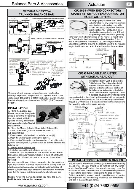
CP5520-3 & CP5520-4<br />
TRUNNION BALANCE BAR.<br />
49.50 MAX 41.52 MAX<br />
5 TURNS<br />
5 TURNS<br />
45.00 24.00 36.52<br />
35.80<br />
71.60<br />
BALANCE BAR SHOWN CENTRAL<br />
11.00<br />
Ø10.00<br />
1.00<br />
MAXIMUM RECOMMENDED<br />
ADJUSTMENT<br />
The maximum<br />
recommended<br />
adjustment<br />
allowed is<br />
5.00mm or<br />
5 turns in<br />
either<br />
direction.<br />
13.00°<br />
MAX<br />
54.00<br />
27.00<br />
22.00<br />
22.00<br />
5.00 MAX<br />
5 TURNS<br />
7.00<br />
7.00<br />
CP5520-3 ANGLED TRUNNION BALANCE BAR ASSEMBLY<br />
R2.50<br />
TYP<br />
R2.50<br />
TYP<br />
32.00<br />
74.00<br />
32.00<br />
74.00<br />
14.50°<br />
13.50°<br />
MUST OPERATE<br />
WITHIN THESE LIMITS<br />
CP5520-4 STRAIGHT TRUNNION BALANCE BAR ASSEMBLY<br />
MUST OPERATE WITHIN ±0.50°<br />
FROM HORIZONTAL<br />
M4x0.50 HOLE FOR CABLE ADJUSTER, 2 OFF M4x0.50<br />
GRUB SCREWS TO RETAIN CABLE INCLUDE.<br />
AP RACING CABLE ADJUSTER - CP2905-18<br />
SPARES:<br />
1 - BALANCE BAR - CP5517-127<br />
2 - SPACER - CP5517-124<br />
3 - CIRCLIP - CP5517-123<br />
4 - CABLE SCREWS - CP5500-113<br />
5 - TRUNNION BAR ASSY<br />
SPARES:<br />
6 - M3 BUTTON HEAD<br />
SCREW - CP3714-119<br />
7 - BOOT CLAMPING<br />
PLATE - CP5517-145<br />
8 - RUBBER BOOT<br />
- CP5517-144<br />
These small and compact balance bars use needle roller<br />
bearings, to provide low hysteresis and high effi ciency. These<br />
versions are designed to fi t at the fi xed end of master cylinders<br />
fi tted with integral trunnions such as CP6465 (Pull Type) and<br />
CP5854.<br />
INSTALLATION.<br />
A. Fitting the Balance Bar.<br />
Please make sure the cylinder<br />
angle is correct to the balance<br />
bar, otherwise it will fail to<br />
operate properly. This means<br />
the balance has to be fi tted at<br />
the fi xed end.<br />
B. Fitting the Master Cylinder Clevis to the Balance Bar.<br />
1. Instal balance bar (1) inside the central trunnion<br />
sub-assembly (5).<br />
2. Place master cylinder clevis on to balance bar (1).<br />
3. Push the washer (2) on the balance bar (1).<br />
4. Push circlip (3) into place on balance bar (1) to hold master<br />
cylinder clevis in place. Cylinder should be able to rotate on the<br />
balance bar.<br />
C. Setting up the Balance Bar.<br />
1. Install remote cable and retaining screws (4).<br />
2. Adjust the cylinder pullrods so that they are perpendicular to<br />
the balance bar under maximum load. It is more effi cient when<br />
perpendicular. It is not important to be perpendicular when<br />
released.<br />
For maximum effi ciency, it is recommended that the pedal is at<br />
right angle with the pushrods under maximum braking load; and<br />
also keeping the balance bar central with better selection of<br />
master cylinder sizes helps to reduce ineffi ciencies. Also make<br />
sure that the master cylinder pistons fully return before use.<br />
Special Note: The more adjustment you have the more<br />
ineffi cient the balance bar becomes<br />
Actuation<br />
CP2905-8 (WITH END CONNECTOR)<br />
CP2905-18 (WITHOUT END CONNECTOR<br />
CABLE ADJUSTERS.<br />
Is a high quality Balance Bar Cable<br />
Adjuster ideal for any competition vehicle<br />
Anodised aluminium alloy body with<br />
¼ turn click stops for positive vibration<br />
proof positioning. The Ø3.8mm inner<br />
steel cable has a polyethylene ‘FR’ self<br />
extiguishing outer tube and is generally<br />
stiffer than most adjuster cables on the market to resist ‘wind<br />
up’. The adjuster body can easily be fi tted through a Ø19mm<br />
hole in the dashboard. Supplied in 1200mm lengths with an<br />
adjustable end fi tting allowing the cable to be cut to the required<br />
length, the kit includes cable clips and two directional stickers.<br />
3/8” UNF<br />
THREAD<br />
SLEEVE DIA. Ø6.4<br />
20.0 1200 MAX<br />
PANEL (FIXING)<br />
THICKNESS MAX 8.5<br />
BARREL DIA. Ø20.0<br />
38.0 18.5<br />
CP2905-15 CABLE ADJUSTER<br />
WITH DIGITAL READ-OUT.<br />
Incorporates the CP2905-8 Balance Bar<br />
Cable Adjuster. The balance bar digital<br />
read-out provides the user with an<br />
accurate indication of exact position of<br />
the balance bar to the right or the left of<br />
centre. The illuminated display is mounted<br />
in a plastic housing with two fi xing points<br />
for mounting to the dashboard and is supplied with approximately<br />
18” of cable to the transducer. The adjuster body can be fi tted<br />
through a Ø19mm hole in the dashboard or bulkhead also using<br />
the mounting plate for increased security.<br />
Ø6.5 MTG HOLE<br />
TOGGLE SWITCH<br />
9V BLOCK BATTREY TERMINAL<br />
CABLE LENGTH APPROX<br />
180MM<br />
Ensure that the balance bar is correctly installed and turns freely<br />
(see above). The cable should not be installed with any bends<br />
of less than 50mm (2”) radius otherwise wind-up may occur. For<br />
maximum stiffness the outer cable should be securely fastened<br />
in place along its complete length using the clips provided.<br />
Cut the cable to the required length preferably using an elastic<br />
grinding wheel, secure end fi tting to balance bar, insert cable<br />
and lock in place with grub screw.<br />
www.apracing.com +44 (0)24 7663 9595<br />
10<br />
DIGITAL LCD SCREEN<br />
Ø26.50<br />
MAX<br />
20.25<br />
2 MTG<br />
MAX<br />
HOLES Ø5.5<br />
30.5<br />
MAX<br />
25.25<br />
50.5<br />
80.5 MAX<br />
3/8”x24UNF<br />
Ø24.0<br />
MAX<br />
Ø14.25 MAX<br />
14<br />
40<br />
31<br />
Ø3.8<br />
CABLE<br />
Ø6.4<br />
SLEEVE<br />
13.0<br />
MAX<br />
Ø12.0<br />
MAX<br />
Ø4.5<br />
CABLE<br />
20<br />
DISPLAY SIZES<br />
CABLE LENGTH APPROX 200MM<br />
ELECTRICAL CABLE LENGTH<br />
APPROX 400MM<br />
110.0 MAX 40.0<br />
MAX<br />
61.0 MAX 8.5 MAX<br />
1.5<br />
PANEL<br />
THICKNESS<br />
60.0 MAX<br />
1200.0 MAX<br />
19.5<br />
MAX<br />
19.0<br />
29.5<br />
34.5<br />
MAX<br />
25.40<br />
(1”) A/F NUT<br />
MTG<br />
Ø19.0<br />
INSTALLATION OF ADJUSTER CABLES<br />
Ø29.5<br />
OVER<br />
KNURL<br />
85