HT211EN (1)
Gehärtete Teleskopschienen
Gehärtete Teleskopschienen

Create successful ePaper yourself
Turn your PDF publications into a flip-book with our unique Google optimized e-Paper software.
TECHNICAL SPECIFICATIONS<br />
NTA-H, NTS-H, NTSF-H<br />
Telescopic rails are ball guided slides used when reduced encoumberances<br />
are required. Hardened telescopic line is the range of Nadella rails<br />
developed for those applications requiring high loads, heavy duty cycles<br />
and smooth running.<br />
Thanks to the cold drawn profiles and induction hardened raceways, now<br />
re-designed with a new optimized shape to better control the clearance<br />
and minimize the sliding force, Nadella Hardened Telescopic Line allows a<br />
smoother sliding and a low deflection also for the most exigent applications.<br />
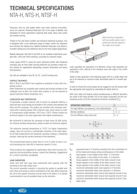
Ideal mounting configuration<br />
with two parallel guides, load in<br />
preferential direction applied in<br />
the middle of the sliders.<br />
Nadella telescopic rails NTA-H and NTS-H are available respectively available<br />
with ~60% and 100% extension, according to customer needs.<br />
Linear guides NTSF-H, using the same optimised profile with Hardened<br />
raceways, plus an inner slider running inside the rail, provides a linear motion<br />
solution for applications demanding compact dimensions and heavy<br />
duty dynamics.<br />
Our rails are available in size 28, 33, 43 - and 63 coming soon.<br />
SURFACE TREATMENT<br />
NTA-H, NTS-H and NTSF-H are supplied as standard in steel with zincplating<br />
surface.<br />
Other treatments are available upon request and already included in the<br />
catalogue such as NC4 zinc-nickel alloy coating, or can be required as<br />
special execution (Black phosphate, etc.).<br />
LUBRICATION AND TEMPERATURE<br />
To guarantee a proper exercise and to ensure an adequate lifetime, a<br />
lubricant layer must always be provided in the contact area between the<br />
balls and the raceways. The guides are provided with raceways lubricated<br />
with a bearing grease with a Barium soap, which allows to work<br />
in a temperature range between -20°C and +120°C. Please contact our<br />
technical support if you plan application with higher temperatures.<br />
Load capacities are expressed in N (Newton), torque load capacities are<br />
expressed in Nm, referred to the Cartesian axes with origin in the centre<br />
of the slider.<br />
Tables of load capacities in the following pages refer to a single slider and<br />
are to be intended as maximum static admissible loads for a smooth operation.<br />
In order to choose the correct guide rail we suggest to use the product with<br />
the appropriate load capacity by calculating the safety factor S F .<br />
With more loads and torques acting simultaneously in different directions<br />
the check of the loads shouldn‘t be on the single component, but the contemporary<br />
action of all the components should be considered (P eq ).<br />
OPERATING CONDITIONS<br />
For high stiffness, low dynamics, low contaminations 1.5<br />
Normal conditions 1.5 - 2<br />
For low stiffness, heavy duty cicle 2 - 3<br />
f s<br />
We recomend to lubricate the raceways at least every 50 000 cycles.<br />
For extreme working temperature, please contact our technical support.<br />
The maximum working temperature is 170°C, for higher temperature<br />
ranges, take into account a considerable reduction of the load capacity<br />
(at high temperatures the hardened raceways undergo a tempering<br />
process, reducing the surface hardness of the elements).<br />
The recommended speed is lower than 0,5 m/s in order to have a correct<br />
functioning (for rails NTS-H maximum speed 0,3 m/s).<br />
These products are suggested for applications with small inversion frequencies<br />
and accelerations (please, consult the following «Suggestions<br />
for a correct mounting» paragraph).<br />
LOAD CAPACITIES<br />
Guide rails with ball cage have preferential load capacity with the<br />
mounting on the side (major axis).<br />
The correct assembly consists in mounting the guides in parallel with<br />
each other and having a uniform distribution of the load. When fastening<br />
the rail to the support structure and the load to the sliders, it is always<br />
recommended to use all available holes on the elements.<br />
with:<br />
P eq<br />
P 1<br />
P 2<br />
M 1<br />
M 2<br />
M 3<br />
C y<br />
C z<br />
M x<br />
M y<br />
M z<br />
f s<br />
S F =<br />
(<br />
C y<br />
P eq<br />
) > f s<br />
P 2 M 1 M 2 M 3<br />
P eq = P 1 +<br />
(<br />
+ + +<br />
) x C y<br />
C z M x M y M z<br />
equivalent load in Y direction resulting from the combination of<br />
all the loads and torques acting contemporary on the slider<br />
load applied in the middle of the slider in Y direction<br />
load applied in the middle of the slider in Z direction<br />
torque applied in the middle of the slider around X axis<br />
torque applied in the middle of the slider around Y axis<br />
torque applied in the middle of the slider around Z axis<br />
maximum admissible static load capacity in Y direction<br />
maximum admissible static load capacity in Z direction<br />
maximum admissible static torque load capacity around X axis<br />
maximum admissible static torque load capacity around Y axis<br />
maximum admissible static torque load capacity around Z axis<br />
static factor<br />
26 |