HT211EN (1)
Gehärtete Teleskopschienen
Gehärtete Teleskopschienen

You also want an ePaper? Increase the reach of your titles
YUMPU automatically turns print PDFs into web optimized ePapers that Google loves.
4.1<br />
LIFETIME<br />
The lifetime of the guide rail is the maximum stroke (in km for rails<br />
NTSFH) or maximum number of cycles (for rails NTA-H and NTS-H), that<br />
the guide rail will be able to reach before the plastic deformation on the<br />
raceways occurs.<br />
For rails NTSFH<br />
For rails NTAH and NTSH<br />
with:<br />
C 100<br />
C dyn<br />
P eq<br />
f d<br />
C 100 1 3<br />
L km = 100 x x<br />
(<br />
P eq f d<br />
)<br />
C dyn 1 3<br />
L cycles = 100000 x x<br />
(<br />
P eq f d<br />
)<br />
dynamic load in Y direction [N], valued according to standard<br />
ISO 14728-2 for the calculation of the lifetime in km (rails<br />
NTSFH)<br />
dynamic load in Y direction [N], valued according to standard<br />
ISO 14728-2 for calculation of the lifetime in cycles (rails NTAH<br />
and NTSH)<br />
equivalent load in Y direction resulting from the combination<br />
of all the loads and torques acting contemporary on the slider<br />
(see formula above)<br />
dynamic factor<br />
SUGGESTIONS FOR A CORRECT MOUNTING<br />
In guide systems based on ball-cage, the sliding occurs thanks to the<br />
simultaneous movement of the slider and of the ball-cage: the slider,<br />
moved by a drive system or manually, sets in motion the ball-cage,<br />
which will cover half of the stroke done by the slider, until reaching<br />
the end-stop.<br />
During operation, with the succession of working cycles and consequent<br />
motion reversals, imperceptible displacements of the ball-cage,<br />
in relation to the position of the slider, occur.<br />
This process, that is defined displacement and leads to a gradual reduction<br />
of the stroke and consequent dragging of the ball-cage on the<br />
raceways, can be slowed down using the race for the entire stroke and<br />
limiting speed and acceleration.<br />
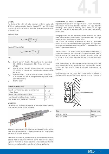
The restoration of the proper functioning must be done by setting a<br />
forced cycle up to the end stop: when the movement of the slider is<br />
commanded by a drive system, we recommend to provide a peak motor<br />
torque 10 times higher (friction coefficient in normal condition is<br />
0,01).<br />
Guide systems based on ball-cages are mostly recommended for horizontal<br />
movements. Vertical installation is not recommended because<br />
the ball-cage tends to fall by gravity, accelerating the process of displacement.<br />
Providing an external end stop is highly recommended in order not to<br />
discharge on the screw of the internal stop the arrest of the machine.<br />
OPERATING CONDITIONS<br />
f d<br />
Smooth operation at low speed at constant load<br />
without shocks<br />
1 - 1.2<br />
Smooth operation with load variation 1.2 - 1.5<br />
Operation with small shocks and vibrations 1.5 - 2<br />
High accelerations, shocks and vibrations 2 - 4<br />
DEFLECTION<br />
The deflection is the elastic deformation you can experience at the edge<br />
of the opened rail when a load is applied.<br />
Size<br />
Chamfer (mm)<br />
NTSF28H, NTA33 1 x 45°<br />
NTSF43H, NTA43 1.5 x 45°<br />
With semi-telescopic rails NTA-H, that can partially exit from the rail, the<br />
deflection will depend almost exclusively on the rigidity of the structures<br />
connected to the guide elements.<br />
For telescopic rails NTS-H, refer to the values of deflection written in the<br />
tables of the load capacities and which refer to the maximum load (C y )<br />
applied in the middle of the opened slider. For applied loads inferior to<br />
the maximum load capacity, reduce the deflection proportionally<br />
| 27