
Create successful ePaper yourself
Turn your PDF publications into a flip-book with our unique Google optimized e-Paper software.
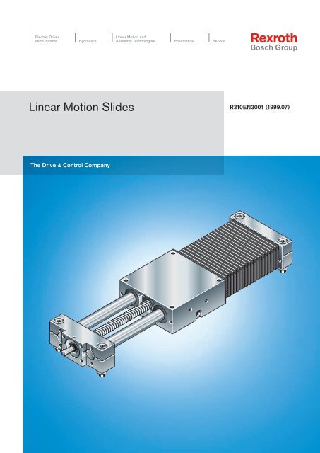
<strong>Linear</strong> <strong>Motion</strong> <strong>Slides</strong><br />
The Drive & Control Company<br />
R310EN3001 (1999.07)
<strong>Linear</strong> <strong>Motion</strong> <strong>Slides</strong><br />
A Solution to Many Problems 4<br />
Product Overview 6<br />
Structure 12<br />
Technical Data 14<br />
Load Capacities and Moments 15<br />
General Information 16<br />
Technical Notes 18<br />
- Size 8-65/12-85 18<br />
- Size 16-100/20-130 20<br />
- Size 25-160/30-180 22<br />
- Size 40-230/50-280 24<br />
<strong>Linear</strong> <strong>Motion</strong> <strong>Slides</strong>, Closed Type without Drive Unit 26<br />
<strong>Linear</strong> <strong>Motion</strong> <strong>Slides</strong>, Closed Type with Ball Screw Drive 30<br />
<strong>Linear</strong> <strong>Motion</strong> <strong>Slides</strong>, <strong>Open</strong> Type without Drive Unit 38<br />
<strong>Linear</strong> <strong>Motion</strong> <strong>Slides</strong>, <strong>Open</strong> Type with Ball Screw Drive 42<br />
Motor Attachment 50<br />
<strong>Linear</strong> <strong>Motion</strong> <strong>Slides</strong> with Toothed Belt Drive 52<br />
- Structure and Technical Data 52<br />
Switch Mounting Arrangements 60<br />
Motors 63<br />
Documentation 66<br />
Inquiry/Order Form 67<br />
R310EN 3001 (1999.07)<br />
3
<strong>Linear</strong> <strong>Motion</strong> <strong>Slides</strong><br />
A Solution to Many Problems<br />
The tasks<br />
• Driving<br />
• Transporting<br />
• Positioning<br />
Total height<br />
Length<br />
Load capacities and moments<br />
Static load<br />
Speed<br />
Precision<br />
System complete<br />
with drive unit<br />
Switch mounting arrangements<br />
Version<br />
Documentation<br />
4 R310EN 3001 (1999.07)
R310EN 3001 (1999.07)<br />
23 mm to 115 mm<br />
up to 5300 mm<br />
Load capacity C up to 36380 N<br />
Longitudinal moment M L up to 3011 Nm<br />
Torsional moment M t up to 2740 Nm<br />
up to 1000 kg<br />
up to 80 m/min<br />
Repeatability of up to 0.005 mm<br />
Positioning accuracy of up to 0.01 mm<br />
AC servomotor, MiniDrive or stepping motor<br />
with motor mount, coupling or side drive with<br />
timing belt (plus control unit)<br />
Switch over total travel range<br />
without drive unit<br />
with ball screw drive<br />
with toothed belt drive<br />
Standard report<br />
Moment of friction measurement<br />
Lead deviation<br />
The solution<br />
<strong>Linear</strong><br />
<strong>Motion</strong> <strong>Slides</strong><br />
5
<strong>Linear</strong> <strong>Motion</strong> <strong>Slides</strong><br />
Product Overview<br />
<strong>Linear</strong> <strong>Motion</strong> <strong>Slides</strong>:<br />
Particularly smooth running and<br />
long service life thanks to Super<br />
<strong>Linear</strong> Bushings<br />
without drive unit<br />
closed <strong>type</strong> - for cantilever-<strong>type</strong> installation<br />
open <strong>type</strong> - for installation with shaft support rails<br />
Lubrication points at both<br />
sides of the carriage, for grease lubrication only<br />
One-point lubrication<br />
Various possibilities for<br />
motor attachment<br />
Oil and moisture-proof<br />
PU bellows-<strong>type</strong> protective<br />
cover (the last fold is mechanically<br />
clamped)<br />
with Precision<br />
Ball Screw Assembly<br />
Higher travel speeds possible<br />
with larger ball screw drives<br />
6 R310EN 3001 (1999.07)
Revised design<br />
Greater flexi-<br />
bility due to<br />
options.<br />
Ready for<br />
installation<br />
with different<br />
attachments<br />
Longer stroke for specified length<br />
R310EN 3001 (1999.07)<br />
without drive unit<br />
Precision Ball Screw Assembly<br />
in rolled quality. Tolerance class T7 according<br />
to DIN 69051 with clearancefree<br />
cylindrical nut<br />
Wide, steel-reinforced toothed<br />
polyurethane drive belt for extreme<br />
stiffness and positioning accuracy<br />
requirements<br />
Screw Drive<br />
Length as desired<br />
Optimized shaft clamping force<br />
with toothed belt drive<br />
with toothed belt drive<br />
Tension end enclosure with integral<br />
belt tensioning system. Belt<br />
pulley system with ball bearings<br />
lubricated for life<br />
7
<strong>Linear</strong> <strong>Motion</strong> <strong>Slides</strong><br />
Product Overview<br />
Motor Selection<br />
in accordance with controllers and<br />
control systems<br />
A choice can be made between several<br />
different motor/controller combinations to<br />
achieve the most cost-efficient solution for<br />
each customer application. The motor/controller<br />
combination must always be taken<br />
into account when sizing the drive.<br />
For more detailed information on motors<br />
and control systems, please refer to catalog<br />
RE 82700 “Controllers, Motors, Electrical<br />
Accessories”.<br />
Digital AC servomotor<br />
MiniDrive<br />
3-phase stepping motor<br />
MKD 25B-144-KG1<br />
MKD 41B-144 KG1<br />
MKD 71B-061 KG1<br />
MKD 71B-097 KG1<br />
MMD 022A<br />
MMD 042A<br />
MMD 082A<br />
VRDM 368<br />
VRDM 397<br />
VRDM 3910<br />
VRDM 3913<br />
8 R310EN 3001 (1999.07)
STAR step<br />
Hand<br />
Auto<br />
RS232<br />
ckkdmd1mt.eps<br />
ckksteupt.eps<br />
ckksteupt.eps<br />
ckksteupt.eps<br />
ckksteupt.eps<br />
R310EN 3001 (1999.07)<br />
DKC<br />
DKS<br />
DDS<br />
DMD<br />
WD3<br />
PC<br />
Profi<br />
step<br />
Digital controller<br />
The low-cost solution for<br />
single-axis and multi-axis<br />
systems<br />
Digital positioning<br />
module and DLC controls<br />
The universal solution for<br />
one axis<br />
Digital controllers and CLM<br />
analog positioning module<br />
The convenient solution for<br />
multi-axis systems<br />
Digital controller<br />
Power output section<br />
for control cabinet installation<br />
PC controller board<br />
Stepping motor controller<br />
Single-axis and multiple-<br />
axis positioning controls<br />
with power output section<br />
The complete solution<br />
ckkschaltpt.eps<br />
STAR step<br />
Hand<br />
RS232<br />
Auto<br />
<strong>Linear</strong> <strong>Motion</strong> <strong>Slides</strong> can be supplied<br />
complete with motor, controller and control<br />
system.<br />
9
<strong>Linear</strong> <strong>Motion</strong> <strong>Slides</strong><br />
Product Overview<br />
Type designation (size)<br />
The linear motion slides are designated<br />
according to <strong>type</strong> and size.<br />
The term slide is used to describe a specific<br />
combination of <strong>type</strong> and size.<br />
“<strong>Linear</strong> motion slide” is abbreviated to<br />
slide in the following tables.<br />
<strong>Linear</strong> <strong>Motion</strong><br />
<strong>Slides</strong><br />
Closed <strong>type</strong><br />
<strong>Linear</strong> <strong>Motion</strong><br />
<strong>Slides</strong><br />
<strong>Open</strong> <strong>type</strong><br />
1) Size 8-65 with Standard <strong>Linear</strong> Bushing<br />
Slide (example) =<br />
System = <strong>Linear</strong> <strong>Motion</strong> Slide (S)<br />
Guideway = Closed-<strong>type</strong> linear bushing (G)<br />
<strong>Open</strong>-<strong>type</strong> linear bushing (O)<br />
Drive unit = Without drive unit (O)<br />
Precision Ball Screw Assembly (K)<br />
Toothed belt (R)<br />
Dimensions<br />
of guideway =<br />
Overall<br />
width =<br />
SGO<br />
SGK<br />
SGR<br />
10 PictoAntrieb2.eps R310EN 3001 (1999.07)<br />
d<br />
B<br />
Type<br />
S G K 16- 100<br />
Type Slide Guideway Drive unit<br />
SOO<br />
SOK<br />
SOR<br />
Super <strong>Linear</strong> Bushing A<br />
closed <strong>type</strong><br />
Super <strong>Linear</strong> Bushing A<br />
open <strong>type</strong><br />
without drive unit<br />
Precision Ball Screw Assembly<br />
Toothed belt drive<br />
PictoAntrieb2.eps<br />
Size<br />
11.01.94 without drive unit<br />
Precision Ball Screw Assembly<br />
Toothed belt drive
Suitable load<br />
(recommended value on the basis<br />
of past experience)<br />
Note on dynamic load capacities<br />
and moments:<br />
Size: d-B<br />
R310EN 3001 (1999.07)<br />
As far as the desired service life is concerned,<br />
loads of up to approximately<br />
20% of the dynamic load and moment<br />
values (C, Mt , ML ) have proved acceptable.<br />
The following values may not be exceeded:<br />
The dynamic load capacities and moments<br />
are based on 100,000 m travel. However,<br />
a travel of just 50,000 m is often taken as<br />
a basis. If this is the case, for comparison<br />
purposes:<br />
Multiply values C, Mt and ML by 1.26.<br />
Dynamic load capacity C (N)<br />
– the maximum permissible deflection<br />
– the maximum permissible drive torque<br />
8-65 12-85 16-100 20-130 25-160 30-180 40-230 50-280<br />
Page 26 1040 2500 3050 6040 11820 14360 24660 36060<br />
Page 30 2500 3050 6040 11820 14360 24660 36060<br />
Page 56 11820<br />
Page 40 2850 3440 6100 11950 14520 24950 36380<br />
Page 44 2850 3440 6100 11950 14520 24950 36380<br />
Page 56 11950<br />
B<br />
d<br />
11
<strong>Linear</strong> <strong>Motion</strong> <strong>Slides</strong><br />
Structure<br />
Structure<br />
<strong>Linear</strong> <strong>Motion</strong> <strong>Slides</strong><br />
(closed or open <strong>type</strong>)<br />
A with ball screw drive<br />
B without drive unit<br />
C with toothed belt drive<br />
1 Ball screw drive with clearance-free<br />
cylindrical single nut<br />
2 End block fixed bearing<br />
3 Carriage with four Super <strong>Linear</strong><br />
Bushings (closed or open <strong>type</strong>)<br />
4 PU bellows-<strong>type</strong> protective cover<br />
5 End block floating bearing<br />
6 Shaft support rails<br />
(for open version only)<br />
Accessories:<br />
7 Socket-plug<br />
8 Mechanical switch (with mounting<br />
components)<br />
9 Proximity switch (with mounting<br />
components)<br />
10 Switching cam<br />
11 Cable duct (aluminum alloy)<br />
12 Mounting bracket<br />
13 Mounting profile<br />
14 Motor<br />
15 Motor mount and coupling<br />
16 Side drive with timing belt<br />
14<br />
A<br />
B<br />
C<br />
2<br />
15<br />
1<br />
12 R310EN 3001 (1999.07)<br />
12<br />
7<br />
6<br />
3<br />
13<br />
11<br />
4<br />
9 10<br />
16<br />
5<br />
14<br />
8
Motor attachment with mount<br />
and coupling<br />
A motor can be attached via a mount<br />
and coupling to all <strong>Linear</strong> <strong>Motion</strong> <strong>Slides</strong><br />
equipped with a ball screw drive.<br />
The motor mount serves both to attach the<br />
motor to the <strong>Linear</strong> <strong>Motion</strong> Slide and as an<br />
enclosed housing for the coupling.<br />
The coupling transmits the motor drive<br />
torque free of stresses to the <strong>Linear</strong> <strong>Motion</strong><br />
Slide drive shaft.<br />
Our standard couplings compensate for the<br />
thermal expansion of the system.<br />
If other makes of couplings are used, the thermal<br />
expansion must be taken into account.<br />
1 Motor<br />
2 Motor mount<br />
3 Coupling<br />
4 <strong>Linear</strong> <strong>Motion</strong> Slide<br />
Motor attachment via side<br />
drive with timing belt<br />
For <strong>Linear</strong> <strong>Motion</strong> <strong>Slides</strong> from size 25-160<br />
and up, the motor can be attached via a<br />
side drive with timing belt. This results in<br />
a shorter overall length compared to a<br />
motor attachment with motor mount and<br />
coupling.<br />
The compact enclosed housing provides<br />
belt protection and secures the motor.<br />
In addition, different gear ratios are available:<br />
i = 1 : 1<br />
i = 1 : 1.5 (size 25-160, 30-180)<br />
i = 1 : 2 (size 40-230, 50-280)<br />
The side drive with timing belt can be<br />
mounted in four directions:<br />
– bottom, top (RV01 and RV02)<br />
– left, right (RV03 and RV04)<br />
1 <strong>Linear</strong> <strong>Motion</strong> Slide<br />
2 Drawn, anodized aluminum frame<br />
3 Toothed belt<br />
4 AC servomotor<br />
5 Pre-tensioning of the toothed belt:<br />
Apply pre-tensioning force Fv to motor<br />
(Fv will be indicated on delivery)<br />
6 Attachment of belt pulleys with<br />
clamping assemblies<br />
7 Cover plate<br />
8 End cover<br />
9 On sizes 25-160 and 30-180:<br />
Ball screw journal with additional support<br />
bearing<br />
R310EN 3001 (1999.07)<br />
2<br />
9<br />
3<br />
5<br />
8<br />
6<br />
7<br />
1 2 3 4<br />
Fv<br />
1<br />
4<br />
13
<strong>Linear</strong> <strong>Motion</strong> <strong>Slides</strong><br />
Technical Data<br />
Drive data for side drive with timing belt, fixed bearing end, for motor attachment via side drive with timing belt<br />
<strong>Linear</strong> <strong>Motion</strong><br />
Slide<br />
Motor<br />
Friction moment M RRv (Nm)<br />
SGK 25-160<br />
SOK 25-160<br />
SOK 30-180<br />
SOK 30-180<br />
Gear ratio i = ...<br />
SGK 40-230<br />
SOK 40-230<br />
SOK 50-280<br />
SOK 50-280<br />
Ball screw<br />
20 x 5<br />
20 x 20<br />
25 x 10<br />
Permissible torque<br />
up to length L = ... at (1)<br />
(mm)<br />
1700<br />
1600<br />
2900<br />
Technical data of AC servomotors<br />
and MiniDrive<br />
Motor<br />
Maximum effective speed nmax Rated torque MMN Maximum torque Mmax Mass moment of inertia JM + JBr Brake holding torque M Br<br />
Mass with brake m Br<br />
d 0 x P<br />
32 x 5<br />
32 x 10<br />
32 x 20<br />
32 x 32<br />
i = 1<br />
(Nm)<br />
2.6<br />
6.9<br />
5.0<br />
i = 1.5<br />
(Nm)<br />
1.7<br />
4.6<br />
3.3<br />
0.4<br />
Reduced mass moment of<br />
inertia at<br />
i = 1<br />
(· 10-6 kgm2 (· 10 )<br />
-6 kgm2 )<br />
250 84<br />
14 R310EN 3001 (1999.07)<br />
i = 1.5<br />
L MRv MRv JRv JRv MRv … Permissible system torque for with timing belt side drive on the motor journal<br />
(take max. motor torque MMmax into account)<br />
MRRv … Friction moment, timing belt side drive on the motor journal<br />
JRv … Reduced mass moment of inertia, timing belt side drive<br />
i … Reduction, timing belt side drive<br />
(1) … Permissible torque for longer lengths on request<br />
Coupling Data<br />
Couplings with data as shown in the table<br />
are used with standard servomotors.<br />
(1/min)<br />
(Nm)<br />
(Nm)<br />
(10-6 kgm2 )<br />
(Nm)<br />
(kg)<br />
MKD 41B/MMD 082A<br />
MKD 41B-144 KG1<br />
2.7<br />
170 + 16<br />
2.2<br />
4.65<br />
Permissible torque<br />
up to length L = ... at (1)<br />
(mm)<br />
i = 1<br />
(Nm)<br />
MKD 71B<br />
i = 2<br />
(Nm)<br />
0.45<br />
Reduced mass moment<br />
of inertia at<br />
i = 1<br />
i = 2<br />
L MRv MRv JRv JRv 2250<br />
2250<br />
2750<br />
3250<br />
MKD 71B-061<br />
8<br />
870 + 38<br />
5<br />
9.17<br />
11.8<br />
19.4<br />
19.4<br />
19.4<br />
5.9<br />
10.8<br />
12.9<br />
12.9<br />
(· 10-6 kgm2 (· 10 )<br />
-6 kgm2 )<br />
1450 280<br />
<strong>Linear</strong> Motor <strong>type</strong> Rated torque Mass Coupling<br />
<strong>Motion</strong> of coupling M K moment mass<br />
Slide size of inertia J K<br />
(Nm) (10 -6 kgm 2 ) (kg)<br />
12 / 16 MMD 022 3.7 7 0.075<br />
MKD 25<br />
20 MKD 41 19 57 0.26<br />
MMD 042<br />
MMD 082 9 61 0.26<br />
25 / 30 MKD 41 19 57 0.26<br />
MMD 082 14.5 63 0.26<br />
40 / 50 MKD 71B-061 50 200 0.7<br />
MKD 71B-097<br />
MMD 082A<br />
3000<br />
2.4<br />
6.9<br />
133 + 8<br />
2.4<br />
3.7
Load Capacities and Moments<br />
Size<br />
d-B<br />
R310EN 3001 (1999.07)<br />
Dynamic<br />
load capacity<br />
C (N)<br />
Closed <strong>type</strong><br />
Dynamic moments<br />
M t (Nm) M L (Nm)<br />
8 - 65 1040 16 15<br />
12 - 85 2500 52 57<br />
16 -100 3050 82 87<br />
20 -130 6040 217 229<br />
25 -160 11820 520 549<br />
30 -180 14360 689 725<br />
40 -230 24660 1504 1713<br />
50 -280 36060 2740 3011<br />
Note on dynamic load capacities<br />
and moments<br />
ML<br />
Reduced load capacity in short-stroke<br />
applications<br />
In short-stroke applications, the service<br />
life of the shafts is shorter than that of the<br />
Super <strong>Linear</strong> Bushings.<br />
For this reason, the load capacities list ed in<br />
the tables must be multiplied by the factor<br />
f w .<br />
The load capacities of the open versions are<br />
reduced as follows under lift-off loads:<br />
Sizes 12 and 16 to 42%<br />
Sizes 20 to 50 to 60%<br />
Nominal service life<br />
d<br />
C<br />
Mt<br />
B<br />
Dynamic<br />
load capacity<br />
C (N)<br />
ML<br />
<strong>Open</strong> <strong>type</strong><br />
Mt<br />
2850 25 27<br />
3440 39 41<br />
6100 134 141<br />
11950 320 339<br />
14520 425 447<br />
24950 928 1057<br />
36380 1687 1853<br />
The dynamic load capacities and moments are based on 100,000 m travel.<br />
However, a travel of just 50,000 m is often taken as a basis. If this is the case,<br />
for comparison purposes:<br />
Multiply values C, Mt and ML by 1.26.<br />
1,0<br />
0,9<br />
0,8<br />
0,7<br />
0,6<br />
0,5<br />
f w<br />
C' Sizes 12 and 16<br />
C‘ = 0.42 · C<br />
Sizes 20 to 50<br />
C‘ = 0.6 · C<br />
C<br />
P<br />
L = ( ) 3<br />
L h =<br />
12 16 20 25 30 40<br />
L<br />
60 · vm · 10 5<br />
C'<br />
L nominal service life (m)<br />
Lh nominal service life (h)<br />
C dynamic load capacity (N)<br />
P equivalent dynamic load (N)<br />
vm average speed (m)<br />
d<br />
C<br />
B<br />
Dynamic moments<br />
M t (Nm) M L (Nm)<br />
0 20 40 60 80 100 120 140 160 180 200 220 240 260<br />
50<br />
Stroke<br />
(mm)<br />
15
<strong>Linear</strong> <strong>Motion</strong> <strong>Slides</strong><br />
General Information<br />
Delivery condition:<br />
Assemblies without drive unit:<br />
Delivered as separate parts. The carriage is mounted as a sub-assembly.<br />
The fixing screws are not included in the package.<br />
<strong>Open</strong> Type SOO:<br />
The Precision Steel Shafts are screwed to the Shaft Support Rails.<br />
Assemblies with drive unit: The <strong>Linear</strong> <strong>Motion</strong> <strong>Slides</strong> with ball screw drive and toothed belt drive<br />
(SGK, SGR, SOR and SOK) are delivered fully assembled and greased.<br />
Length L:<br />
Permissible shaft deflection in<br />
the <strong>Linear</strong> Bushing closed <strong>type</strong>:<br />
Maximum permissible drive<br />
torque M per :<br />
Weight of the <strong>Linear</strong> <strong>Motion</strong> Slide:<br />
Shafts for <strong>Linear</strong> <strong>Motion</strong> <strong>Slides</strong><br />
without drive unit:<br />
<strong>Linear</strong> <strong>Motion</strong> <strong>Slides</strong> consist of components of varying length and assemblies of fixed<br />
length. The length-dependent components are cut to size to suit each particular application.<br />
<strong>Linear</strong> <strong>Motion</strong> <strong>Slides</strong> can thus be custom-designed and completed in a variety of<br />
lengths (infinitely variable). Lengths exceeding the specified maximum L max are available on<br />
request.<br />
Due to the use of Super <strong>Linear</strong> Bushings (except for <strong>Linear</strong> <strong>Motion</strong> Slide<br />
size 8-65), higher shaft deflection is permissible than for conventional linear bearings.<br />
Selection of the length (L) and the size of slide should take account of the permissible<br />
shaft deflection (tan α).<br />
tan α max = 8.72 · 10 -3 =^ 0.5°<br />
tan α ≤ tan α max<br />
Size 8-65:<br />
<strong>Linear</strong> <strong>Motion</strong> <strong>Slides</strong> are also available with:<br />
- corrosion resistant steel shafts to DIN 17230 / EN 10088<br />
- Resist steel shafts: zinc/iron coating with yellow chromating<br />
For further details on Resist, please ask for catalog RE 82 050.<br />
For further details on <strong>Linear</strong> Bushings and Precision Steel Shafts,<br />
please ask for catalog RE 83 100.<br />
tan α max = 10 · 10 -4<br />
The values of Mper given in the graphs (see Technical Notes) are based on the follow ing<br />
assumptions:<br />
• Horizontal operation<br />
• No radial load on the ball screw drive journal<br />
• The torque rating of the coupling is not taken into account<br />
The maximum permissible drive torque (see Technical Notes) is reduced for ball screw drives<br />
with keyway. The keyway produces a notch effect and reduces the effective dia -meter.<br />
(Information on side drive with timing belt available on request.)<br />
Weight calculation does not include motor attachment, switches or side drive with timing<br />
belt.<br />
Weight (kg/mm) ∙ Length L (mm) + Weight of all fixed-length components (kg)<br />
16 R310EN 3001 (1999.07)
R310EN 3001 (1999.07)<br />
17
<strong>Linear</strong> <strong>Motion</strong> <strong>Slides</strong><br />
Technical Notes – Size 8-65/12-85<br />
8-65<br />
Closed <strong>type</strong><br />
Slide Dynamic load<br />
capacity<br />
C<br />
(N)<br />
Dynamic moments<br />
M t<br />
(Nm)<br />
M L<br />
(Nm)<br />
L/2<br />
α<br />
L<br />
18 R310EN 3001 (1999.07)<br />
F<br />
Moved<br />
mass<br />
(kg)<br />
tan α ≤ tan α max<br />
Slide<br />
weight<br />
L in mm<br />
(kg)<br />
Max. length<br />
L max<br />
SGO 8 - 65 1040 16 15 0.28 0.0008 · L + 0.39 700 3<br />
See section on Load Capacities and Moments.<br />
Permissible shaft deflection in the<br />
<strong>Linear</strong> Bushing 1)<br />
<strong>Linear</strong> <strong>Motion</strong> Slide SGO 8 - 65 incorporates<br />
Standard <strong>Linear</strong> Bushings.<br />
The load capacity or service life of the Slide<br />
will therefore be reduced with increasing<br />
shaft deflection.<br />
For further information refer to catalog<br />
RE 83 100 “<strong>Linear</strong> Bushings and Shafts”.<br />
1) Also refer to “General Information”<br />
(mm)<br />
Frictional<br />
force<br />
(N)<br />
tan α = F · (L - 9) · 4.970 · 10 -8<br />
tan α max = 10 · 10 -4<br />
tan α Shaft deflection<br />
F External load (N)<br />
L Dimension “L” (mm)
12-85<br />
Closed <strong>type</strong><br />
<strong>Open</strong> <strong>type</strong><br />
R310EN 3001 (1999.07)<br />
Slide<br />
Ball<br />
screw<br />
d 0 x P<br />
(mm)<br />
Dynamic load capacity Dyn. moments<br />
Guideway<br />
(N)<br />
Fixed<br />
bearing<br />
(N)<br />
Ball<br />
screw<br />
(N)<br />
M t<br />
(Nm)<br />
M L<br />
(Nm)<br />
Moved<br />
mass<br />
(kg)<br />
Slide<br />
weight<br />
L in mm<br />
(kg)<br />
Maximum<br />
length<br />
L max<br />
SGO 12 - 85 2500 52 57 0.55 0.0018 · L + 0.80 1000<br />
SGK 12 - 85 8 x 2.5 2500 5280 2900 52 57 0.54 0.0021 · L + 0.92 1000<br />
SOO12- 85 2850 25 27 0.47 0.0035 · L + 0.47 4000<br />
SOK 12-85 8 x 2.5 2850 5280 2900 25 27 0.47 0.0040 · L + 0.82 1000<br />
See section on Load Capacities and Moments.<br />
Permissible shaft deflection in the<br />
<strong>Linear</strong> Bushing closed <strong>type</strong> 1) :<br />
(mm)<br />
tan α = F · (L - 18) · 1.376 · 10 -8<br />
tan α max = 8.72 · 10 -3<br />
<strong>Linear</strong> <strong>Motion</strong> <strong>Slides</strong> with<br />
Ball Screw Drive:<br />
Maximum speed Maximum permissible drive torque1) α<br />
L<br />
tan α<br />
F<br />
Shaft deflection<br />
External load (N)<br />
tan α ≤ tan αmax L Dimension ”L” (mm)<br />
25.0<br />
20.0<br />
15.0<br />
10.0<br />
5.0<br />
0.0<br />
100<br />
v (m/min)<br />
8 x 2.5<br />
200 300 400 500 600 700 800 900 1000<br />
Mass moment of inertia of linear motion slide:<br />
Frictional force, moment of friction:<br />
Slide without<br />
drive unit<br />
SGO 12 - 85<br />
SOO 12 - 85<br />
J S = ( 0.203 + 0.002 · L + 0.158 · m fr ) · 10 -6<br />
L/2<br />
L (mm)<br />
JS Reduced mass moment of inertia<br />
of linear motion slide with<br />
additional load on the drive journal (kgm2 )<br />
mfr Additional load (kg)<br />
L Dimension “L” (mm)<br />
1) Also refer to “General Information”<br />
Frictional force<br />
(approx. N)<br />
7<br />
F<br />
1.40<br />
8 x 2.5<br />
1.20<br />
Mper (Nm)<br />
1.00<br />
0.80<br />
0.60<br />
0.40<br />
0.20<br />
0.00<br />
100 200 300 400 500 600 700 800<br />
Slide with<br />
drive unit<br />
SGK 12 - 85<br />
SOK 12 - 85<br />
0.06<br />
900 1000<br />
Moment of friction (approx. Nm)<br />
8 x 2.5<br />
L (mm)<br />
19
<strong>Linear</strong> <strong>Motion</strong> <strong>Slides</strong><br />
Technical Notes – Size 16-100/20-130<br />
16-100<br />
Closed <strong>type</strong><br />
<strong>Open</strong> <strong>type</strong><br />
See section on Load Capacities and Moments.<br />
<strong>Linear</strong> <strong>Motion</strong> <strong>Slides</strong> with<br />
Ball Screw Drive:<br />
Maximum speed<br />
90.0<br />
80.0<br />
70.0<br />
60.0<br />
v (m/min)<br />
12 x 10<br />
50.0<br />
40.0<br />
30.0<br />
20.0<br />
12 x 5<br />
10.0<br />
0.0<br />
L (mm)<br />
250 375 500 625 750 875 1000 1125 1250 1375 1500<br />
Mass moment of inertia of linear motion slide:<br />
Frictional force, moment of friction:<br />
Slide without<br />
drive unit<br />
SGO 16 -100<br />
SOO 16-100<br />
Slide<br />
1) Also refer to “General Information”<br />
Ball<br />
screw<br />
d 0 x P<br />
(mm)<br />
J S = ( k1 + k2 · L + k3 · m fr ) · 10 -6<br />
Frictional force<br />
(approx. N)<br />
9<br />
Dynamic load capacity Dyn. moments<br />
JS Reduced mass moment of inertia<br />
of linear motion drives with<br />
additional load on the drive journal (kgm2 k1, k2, k3 Constants (see table)<br />
)<br />
mfr Additional load (kg)<br />
L Dimension “L” (mm)<br />
L/2<br />
α<br />
L<br />
tan α ≤ tan α max<br />
Maximum permissible drive torque 1)<br />
SGK 16-100<br />
SOK 16-100<br />
tan α = F · (L - 21) · 5.381 · 10 -9<br />
tan α max = 8.72 · 10 -3<br />
tan α Shaft deflection<br />
F External load (N)<br />
L Dimension “L” (mm)<br />
250 350 450 550 650 750 850 950 1050 1150 1250 1350 1450<br />
Moment of friction (approx. Nm)<br />
12 x 5<br />
12 x 10<br />
20 R310EN 3001 (1999.07)<br />
F<br />
M t<br />
(Nm)<br />
2.50<br />
2.00<br />
1.50<br />
1.00<br />
0.50<br />
0.00<br />
M L<br />
(Nm)<br />
M per (Nm)<br />
12 x 10<br />
12 x 5<br />
Ball screw:<br />
d0 x P<br />
12 x 5<br />
12 x 10<br />
Slide with<br />
drive unit<br />
k1<br />
1.088<br />
2.367<br />
0.13<br />
Slide<br />
weight<br />
L in mm<br />
(kg)<br />
Constant<br />
k2<br />
0.013<br />
0.013<br />
0.16<br />
Maximum<br />
length<br />
Lmax (mm)<br />
SGO 16-100 3050 82 87 0.82 0.003 · L + 1.2 1500<br />
12 x 5<br />
12 x 10<br />
4990<br />
3270<br />
SGO 16-100 3440 39 41 0.75 0.005 · L + 0.75 4000<br />
12 x 5<br />
4990<br />
SOK 16-100 3440 5280 39 41 0.76 0.006 · L + 1.3 1500<br />
12 x 10<br />
3270<br />
Permissible shaft deflection in the<br />
<strong>Linear</strong> Bushing closed <strong>type</strong> 1) :<br />
Guideway<br />
(N)<br />
Fixed<br />
bearing<br />
(N)<br />
Ball<br />
screw<br />
(N)<br />
Moved<br />
mass<br />
(kg)<br />
k3<br />
0.633<br />
2.533<br />
L (mm)
20-130<br />
Closed <strong>type</strong><br />
<strong>Open</strong> <strong>type</strong><br />
R310EN 3001 (1999.07)<br />
Slide<br />
Ball<br />
screw<br />
d 0 x P<br />
(mm)<br />
Permissible shaft deflection in the<br />
<strong>Linear</strong> Bushing closed <strong>type</strong> 1) :<br />
Dyn. moments<br />
Dynamic load<br />
capacity<br />
M t<br />
(Nm)<br />
M L<br />
(Nm)<br />
Moved<br />
mass<br />
(kg)<br />
Slide<br />
weight<br />
L in mm<br />
(kg)<br />
Maximum<br />
length<br />
L max<br />
16 x 5 12300<br />
SGK 20 -130 16 x 10 6040 13400 9600 217 229 1.8 0.006 · L + 3.0 2500<br />
16 x 16 6200<br />
SOO 20 -130 6100 134 141 1.6 0.008 · L + 1.6 4000<br />
16 x 5 12300<br />
SOK 20-130 16 x 10 6100 13400 9600 134 141 1.6 0.010 · L + 2.7 2500<br />
16 x 16 6200<br />
See section on Load Capacities and Moments.<br />
<strong>Linear</strong> <strong>Motion</strong> <strong>Slides</strong> with<br />
Ball Screw Drive:<br />
Maximum speed<br />
SGO 20 -130 6040 217 229 1.8 0.005 · L + 2.6 2500<br />
80.0<br />
70.0<br />
60.0<br />
v (m/min)<br />
16 x 16<br />
50.0<br />
40.0<br />
16 x 10<br />
30.0<br />
20.0<br />
16 x 5<br />
10.0<br />
0.0<br />
L (mm)<br />
250 500 750 1000 1250 1500 1750 2000 2250 2500<br />
Mass moment of inertia of linear motion slide:<br />
J S = ( k1 + k2 · L + k3 · m fr ) · 10 -6<br />
JS Reduced mass moment of inertia<br />
of linear motion slide with<br />
additional load on the drive journal (kgm2 k1, k2, k3 Constants (see table)<br />
)<br />
mfr Additional load (kg)<br />
L Dimension “L” (mm)<br />
Frictional force, moment of friction:<br />
Slide without<br />
drive unit<br />
SGO 20-130<br />
SOO 20-130<br />
1) Also refer to “General Information”<br />
Frictional force<br />
(approx. N)<br />
11<br />
Guideway<br />
(N)<br />
Fixed<br />
bearing<br />
(N)<br />
Ball<br />
screw<br />
(N)<br />
L/2<br />
F<br />
(mm)<br />
tan α = F · (L - 36) · 2.932 · 10 -9<br />
tan α max = 8.72 · 10 -3<br />
α tan α Shaft deflection<br />
L<br />
F External load (N)<br />
tan α ≤ tan αmax L Dimension “L” (mm)<br />
Maximum permissible drive torque 1)<br />
4.00<br />
3.50<br />
3.00<br />
2.50<br />
2.00<br />
1.50<br />
1.00<br />
0.50<br />
0.00<br />
250<br />
M per (Nm)<br />
16 x 16<br />
16 x 10<br />
16 x 5<br />
500 750 1000 1250 1500 1750 2000 2250 2500<br />
Ball screw drive with keyway: maximum drive torque 3.2 Nm<br />
Ball screw:<br />
Constant<br />
d0 x P k1 k2<br />
k3<br />
16 x 5 3.238 0.039 0.633<br />
16 x 10 6.692 0.039 2.533<br />
16 x 16 13.878 0.039 6.485<br />
Slide with<br />
drive unit<br />
SGK 20-130<br />
SOK 20-130<br />
L (mm)<br />
Moment of friction (approx. Nm)<br />
16 x 5 16 x 10 16 x 16<br />
0.40 0.43 0.46<br />
21
<strong>Linear</strong> <strong>Motion</strong> <strong>Slides</strong><br />
Technical Notes – Size 25-160/30-180<br />
25-160<br />
Closed <strong>type</strong><br />
<strong>Open</strong> <strong>type</strong><br />
Slide<br />
Ball<br />
screw<br />
d 0 x P<br />
(mm)<br />
Dyn. moments<br />
L/2<br />
α<br />
L<br />
22 R310EN 3001 (1999.07)<br />
F<br />
tan α ≤ tan α max<br />
Dynamic load<br />
capacity<br />
M t<br />
(Nm)<br />
M L<br />
(Nm)<br />
Moved<br />
mass<br />
(kg)<br />
Slide<br />
weight<br />
L in mm<br />
(kg)<br />
Maximum<br />
length<br />
Lmax (mm)<br />
SGO 25-160 11820 520 549 3.3 0.008 · L + 4.8 3000<br />
20 x 5 14300<br />
SGK 25-160 20 x 20 11820 17000 9100 520 549 3.3 0.011 · L + 5.5 3000<br />
25 x 10 15800<br />
SOO 25-160 11950 320 339 2.8 0.011 · L + 2.8 5300<br />
20 x 5 14300<br />
SOK 25-160 20 x 20 11950 17000 9100 320 339 2.9 0.015 · L + 5.0 3000<br />
25 x 10 15800<br />
See section on Load Capacities and Moments.<br />
Permissible shaft deflection in the<br />
<strong>Linear</strong> Bushing closed <strong>type</strong> 1) :<br />
<strong>Linear</strong> <strong>Motion</strong> <strong>Slides</strong> with<br />
Ball Screw Drive:<br />
Maximum speed<br />
80.0<br />
70.0<br />
60.0<br />
50.0<br />
v (m/min)<br />
20 x 20<br />
40.0<br />
30.0<br />
25 x 10<br />
20.0<br />
20 x 5<br />
10.0<br />
0.0<br />
L (mm)<br />
250 500 750 1000 1250 1500 1750 2000 2250 2500 2750 3000<br />
J S = ( k1 + k2 · L + k3 · m fr ) · 10 -6<br />
JS Reduced mass moment of inertia<br />
of linear motion slide with<br />
additional load on the drive journal (kgm2 k1, k2, k3 Constants (see table)<br />
)<br />
mfr Additional load (kg)<br />
L Dimension “L” (mm)<br />
Frictional force, moment of friction:<br />
Guideway<br />
(N)<br />
Mass moment of inertia of linear motion slide:<br />
Slide without<br />
Frictional force<br />
drive unit<br />
(approx. N)<br />
SGO 25-160<br />
SOO 25-160<br />
1) Also refer to “General Information”<br />
14<br />
Fixed<br />
bearing<br />
(N)<br />
Ball<br />
screw<br />
(N)<br />
Maximum permissible drive torque 1)<br />
8.00<br />
7.00<br />
6.00<br />
5.00<br />
4.00<br />
3.00<br />
2.00<br />
1.00<br />
0.0<br />
250<br />
M per (Nm)<br />
20 x 20<br />
25 x 10<br />
20 x 5<br />
tan α = F · (L - 43) · 1.468 · 10 -9<br />
tan α max = 8.72 · 10 -3<br />
tan α Shaft deflection<br />
F External load (N)<br />
L Dimension “L” (mm)<br />
500 750 1000 1250 1500 1750 2000 2250 2500 2750 3000<br />
Ball screw drive with keyway: maximum drive torque 4.5 Nm<br />
Ball screw:<br />
Constant<br />
d0 x P k1 k2<br />
k3<br />
20 x 5 8.216 0.100 0.633<br />
20 x 20 39.990 0.100 10.132<br />
25 x 10 23.575 0.256 2.533<br />
Slide with<br />
drive unit<br />
SGO 25-160<br />
SOK 25-160<br />
Moment of friction (approx. Nm)<br />
L (mm)<br />
20 x 5 20 x 20 25 x 10<br />
0.53 0.64 0.66
30-180<br />
Closed <strong>type</strong><br />
<strong>Open</strong> <strong>type</strong><br />
R310EN 3001 (1999.07)<br />
Slide<br />
Ball<br />
screw<br />
d 0 x P<br />
(mm)<br />
Permissible shaft deflection in the<br />
<strong>Linear</strong> Bushing closed <strong>type</strong> 1) :<br />
Dyn. moments<br />
L/2<br />
α<br />
L<br />
F<br />
tan α ≤ tan α max<br />
Dynamic load<br />
capacity<br />
M t<br />
(Nm)<br />
M L<br />
(Nm)<br />
Moved<br />
mass<br />
(kg)<br />
Slide<br />
weight<br />
L in mm<br />
(kg)<br />
Ball screw drive with keyway: maximum drive torque 4.5 Nm<br />
Maximum<br />
lenght<br />
L max<br />
20 x 5 14300<br />
SGK 30 -180 20 x 20 14360 17000 9100 689 725 4.6 0.014 · L + 7,4 3000<br />
25 x 10 15800<br />
SOO 30-180 14520 425 447 4.1 0.016 · L + 4,1 5300<br />
20 x 5 14300<br />
SOK 30-180 20 x 20 14520 17000 9100 425 447 4.2 0.020 · L + 6,8 3000<br />
25 x 10 15800<br />
See section on Load Capacities and Moments.<br />
<strong>Linear</strong> <strong>Motion</strong> <strong>Slides</strong> with<br />
Ball Screw Drive:<br />
Maximum speed<br />
SGO 30-180 14360 689 725 4.7 0.011 · L + 6,7 3000<br />
80.0<br />
70.0<br />
60.0<br />
50.0<br />
v (m/min)<br />
20 x 20<br />
40.0<br />
30.0<br />
25 x 10<br />
20.0<br />
20 x 5<br />
10.0<br />
0.0<br />
L (mm)<br />
250 500 750 1000 1250 1500 1750 2000 2250 2500 2750 3000<br />
Slide without<br />
drive unit<br />
SGO 30 -180<br />
SOO 30 -180<br />
J S = ( k1 + k2 · L + k3 · m fr ) · 10 -6<br />
JS Reduced mass moment of inertia<br />
of linear motion drives with<br />
additional load on the drive journal (kgm2 k1, k2, k3 Constants (see table)<br />
)<br />
mfr Additional load (kg)<br />
L Dimension “L” (mm)<br />
Frictional force, moment of friction:<br />
1) Also refer to “General Information”<br />
Frictional force<br />
(approx. N)<br />
18<br />
Guideway<br />
(N)<br />
Mass moment of inertia of linear motion slide:<br />
Fixed<br />
bearing<br />
(N)<br />
Ball<br />
screw<br />
(N)<br />
Maximum permissible drive torque 1)<br />
8.00<br />
7.00<br />
6.00<br />
5.00<br />
4.00<br />
3.00<br />
2.00<br />
1.00<br />
0.0<br />
250<br />
M per (Nm)<br />
20 x 20<br />
25 x 10<br />
20 x 5<br />
(mm)<br />
tan α = F · (L - 51) · 7.698 · 10 -10<br />
tan α max = 8.72 · 10 -3<br />
tan α Shaft deflection<br />
F External load (N)<br />
L Dimension “L” (mm)<br />
500 750 1000 1250 1500 1750 2000 2250 2500 2750 3000<br />
Ball screw:<br />
Constant<br />
d0 x P k1 k2<br />
k3<br />
20 x 5 9.103 0.100 0.633<br />
20 x 20 54.169 0.100 10.132<br />
25 x 10 27.12 0.256 2.533<br />
Slide with<br />
drive unit<br />
SGO 30 -180<br />
SOK 30 -180<br />
L (mm)<br />
Moment of friction (approx. Nm)<br />
20 x 5 20 x 20 25 x 10<br />
0.53 0.64 0.66<br />
23
<strong>Linear</strong> <strong>Motion</strong> <strong>Slides</strong><br />
Technical Notes – Size 40-230 / 50-280<br />
40-230<br />
Closed <strong>type</strong><br />
<strong>Open</strong> <strong>type</strong><br />
Slide<br />
<strong>Linear</strong> <strong>Motion</strong> <strong>Slides</strong> with<br />
Ball Screw Drive:<br />
Maximum speed<br />
Ball<br />
screw<br />
d 0 x P<br />
(mm)<br />
Dyn. moments<br />
L/2<br />
α<br />
L<br />
24 R310EN 3001 (1999.07)<br />
F<br />
tanα ≤ tanα max<br />
Dynamic load<br />
capacity<br />
M t<br />
(Nm)<br />
M L<br />
(Nm)<br />
Moved<br />
mass<br />
(kg)<br />
Slide<br />
weight<br />
L in mm<br />
(kg)<br />
Ball screw drive with keyway: maximum drive torque 18 Nm<br />
Maximum<br />
length<br />
L max<br />
SGO 40-230 24660 1504 1713 9.4 0.020 · L + 13.3 4000<br />
32 x 5 21500<br />
SGK 40-230<br />
32 x 10<br />
32 x 20<br />
24660 26000<br />
26200<br />
17900<br />
1504 1713 9.3 0.025 · L + 14.2 4000<br />
32 x 32 17800<br />
SOO 40-230 24950 928 1057 8.3 0.026 · L + 8.3 5300<br />
32 x 5 21500<br />
SOK 40-230<br />
32 x 10<br />
32 x 20<br />
24950 26000<br />
26200<br />
17900<br />
928 1057 8.5 0.032 · L + 13.2 4000<br />
32 x 32 17800<br />
See section on Load Capacities and Moments.<br />
Permissible shaft deflection in the<br />
<strong>Linear</strong> Bushing closed <strong>type</strong> 1) :<br />
80.0<br />
70.0<br />
60.0<br />
50.0<br />
v (m/min)<br />
32 x 32<br />
32 x 20<br />
40.0<br />
30.0 32 x 10<br />
20.0<br />
10.0<br />
0.0<br />
32 x 5<br />
500 1000 1500 2000 2500<br />
Slide without<br />
drive unit<br />
SGO 40 -230<br />
SOO 40 -230<br />
J S = ( k1 + k2 · L + k3 · m fr ) · 10 -6<br />
Frictional force, moment of friction:<br />
1) Also refer to “General Information”<br />
Frictional force<br />
(approx. N)<br />
22<br />
Guideway<br />
(N)<br />
3000 3500 4000<br />
Mass moment of inertia of linear motion slide:<br />
Fixed<br />
bearing<br />
(N)<br />
Ball<br />
screw<br />
(N)<br />
L (mm)<br />
JS Reduced mass moment of inertia<br />
of linear motion slide with<br />
additional load on the drive journal (kgm2 k1, k2, k3 Constants (see table)<br />
)<br />
mfr Additional load (kg)<br />
L Dimension “L” (mm)<br />
Maximum permissible drive torque 1)<br />
40.0<br />
35.0<br />
30.0<br />
25.0<br />
20.0<br />
15.0<br />
10.0<br />
M per (Nm)<br />
32 x 32<br />
32 x 20<br />
32 x 10<br />
32 x 5<br />
5.0<br />
0.0<br />
500 1000 1500 2000 2500<br />
Slide with<br />
drive unit<br />
SGO 40 -230<br />
SOK 40-230<br />
(mm)<br />
tan α = F · (L - 79) · 3.407 · 10 -10<br />
tan α max = 8.72 · 10 -3<br />
tan α Shaft deflection<br />
F External load (N)<br />
L Dimension “L” (mm)<br />
3000 3500 4000<br />
Ball screw:<br />
Constant<br />
d0 x P k1 k2<br />
k3<br />
32 x 5 51.8 53 0.712 0.633<br />
32 x 10 69.446 0.712 2.535<br />
32 x 20 138.21 0.667 10.132<br />
32 x 32 268.83 0.667 25.938<br />
L (mm)<br />
Moment of friction (approx. Nm)<br />
32 x 5 32 x 10 32 x 20 32 x 32<br />
1.14 1.24 1.23 1.27
50-280<br />
Closed <strong>type</strong><br />
<strong>Open</strong> <strong>type</strong><br />
R310EN 3001 (1999.07)<br />
Slide<br />
<strong>Linear</strong> <strong>Motion</strong> <strong>Slides</strong> with<br />
Ball Screw Drive:<br />
Maximum speed<br />
Ball<br />
screw<br />
d o x P<br />
(mm)<br />
Dyn. moments<br />
L/2<br />
α<br />
L<br />
F<br />
tan α ≤ tan α max<br />
Dynamic load<br />
capacity<br />
M t<br />
(Nm)<br />
M L<br />
(Nm)<br />
Moved<br />
mass<br />
(kg)<br />
Slide<br />
weight<br />
L in mm<br />
(kg)<br />
Maximum<br />
length<br />
L max<br />
SGO 50-280 36060 2740 3011 16.4 0.031 · L + 22.1 4000<br />
32 x 5 21500<br />
SGK 50-280<br />
32 x 10<br />
32 x 20<br />
36060 26000<br />
26200<br />
17900<br />
2740 3011 16.0 0.036 · L + 22.8 4000<br />
32 x 32 17800<br />
SOO 50-280 36380 1687 1853 14.8 0.039 · L + 14.8 5300<br />
32 x 5 21500<br />
SOK 50-280<br />
32 x 10<br />
32 x 20<br />
36380 26000<br />
26200<br />
17900<br />
1687 1853 14.8 0.046 · L + 21.3 4000<br />
32 x 32 17800<br />
See section on Load Capacities and Moments.<br />
Permissible shaft deflection in the<br />
<strong>Linear</strong> Bushing closed <strong>type</strong> 1) :<br />
80.0<br />
70.0<br />
60.0<br />
50.0<br />
v (m/min)<br />
32 x 32<br />
32 x 20<br />
40.0<br />
30.0 32 x 10<br />
20.0<br />
10.0<br />
0.0<br />
32 x 5<br />
500 1000 1500 2000 2500<br />
Slide without<br />
drive unit<br />
SGO 50 -280<br />
SOO 50 -280<br />
J S = ( k1 + k2 · L + k3 · m fr ) · 10 -6<br />
Frictional force, moment of friction:<br />
1) Also refer to “General Information”<br />
Frictional force<br />
(approx. N)<br />
27<br />
Guideway<br />
(N)<br />
3000 3500 4000<br />
Mass moment of inertia of linear motion slide:<br />
Fixed<br />
bearing<br />
(N)<br />
Ball<br />
screw<br />
(N)<br />
L (mm)<br />
JS Reduced mass moment of inertia<br />
of linear motion slide with<br />
additional load on the drive journal (kgm2 k1, k2, k3 Constants (see table)<br />
)<br />
mfr Additional load (kg)<br />
L Dimension “L” (mm)<br />
Maximum permissible drive torque 1)<br />
40.0<br />
35.0<br />
30.0<br />
25.0<br />
20.0<br />
15.0<br />
10.0<br />
M per (Nm)<br />
32 x 32<br />
32 x 20<br />
32 x 10<br />
32 x 5<br />
5.0<br />
0.0<br />
500 1000 1500 2000 2500<br />
(mm)<br />
tan α = F · (L - 107) · 1.649 · 10 -10<br />
tan α max = 8.72 · 10 -3<br />
tan α Shaft deflection<br />
F External load (N)<br />
L Dimension “L” (mm)<br />
3000 3500 4000<br />
Ball screw drive with keyway: maximum drive torque 18 Nm<br />
Ball screw:<br />
Constant<br />
d0 x P k1 k2<br />
k3<br />
32 x 5 56.025 0.712 0.633<br />
32 x 10 87.214 0.712 2.533<br />
32 x 20 209.28 0.667 10.132<br />
32 x 32 468.78 0.667 25.938<br />
Slide with<br />
drive unit<br />
SGO 50 -280<br />
SOK 50-280<br />
L (mm)<br />
Moment of friction (approx. Nm)<br />
32 x 5 32 x 10 32 x 20 32 x 32<br />
1.14 1.25 1.25 1.30<br />
25
<strong>Linear</strong> <strong>Motion</strong> <strong>Slides</strong>, Closed Type without Drive Unit<br />
Components and Ordering SGO 8-65 to SGO 50-280<br />
* For the end blocks, heights H 4 , H 5 and H 6 and counterbore H 13 , S 2 have been modified.<br />
Order example<br />
Ordering data<br />
<strong>Linear</strong> <strong>Motion</strong> Slide<br />
(Part number): 0260-400-00, 890 mm<br />
Type = OA01<br />
Guideway = 01<br />
Drive unit = 02<br />
Carriage = 01<br />
Cover = 00<br />
Documentation = 01<br />
Slide<br />
(do not use<br />
for order)<br />
SGO 8 - 65<br />
SGO 12 - 85<br />
SGO 16 -100<br />
SGO 20 -130<br />
SGO 25 -160<br />
SGO 30 -180<br />
SGO 40 -230<br />
SGO 50 -280<br />
Part<br />
number<br />
0260-X00-00,<br />
…. mm<br />
0260-900-00<br />
0260-000-00<br />
0260-100-00<br />
0260-200-00<br />
0260-300-00<br />
0260-400-00<br />
0260-500-00<br />
0260-600-00<br />
Description<br />
<strong>Linear</strong> <strong>Motion</strong> Slide SGO 30-180<br />
Length L = 890 mm<br />
without drive unit<br />
with Precision Steel Shafts<br />
with end block B<br />
with standard carriage<br />
without bellows<br />
with maintenance instructions<br />
Old part numbers<br />
The part numbers previously applicable are<br />
replaced by the number 0260.<br />
Interchangeable with:<br />
1040-...-.. *<br />
1040-708-00 : with end block A<br />
1040-808-00 : with end block B<br />
1040-712-00 : with end block A<br />
1040-812-00 : with end block B<br />
1040-716-00 : with end block A<br />
1040-816-00 : with end block B<br />
1040-720-00 : with end block A<br />
1040-820-00 : with end block B<br />
1040-725-00 : with end block A<br />
1040-825-00 : with end block B<br />
1040-730-00 : with end block A<br />
1040-830-00 : with end block B<br />
1040-740-00 : with end block A<br />
1040-840-00 : with end block B<br />
1040-750-00 : with end block A<br />
1040-850-00 : with end block B<br />
26 R310EN 3001 (1999.07)<br />
Type<br />
….<br />
OA01
Standard<br />
shafts<br />
R310EN 3001 (1999.07)<br />
Guideway<br />
..<br />
Shafts of corrosion<br />
resistant steel to<br />
DIN 17230 / EN 10088<br />
Steel shafts<br />
with STAR-<br />
Resist coating<br />
01 02 03<br />
Drive unit<br />
..<br />
(end block)<br />
End block A End block B<br />
Carriage<br />
..<br />
Standard<br />
Cover<br />
..<br />
Polyurethane<br />
bellows<br />
without with<br />
Documentation<br />
..<br />
Maintenance<br />
instructions<br />
01 02 01 00 01 01<br />
27
<strong>Linear</strong> <strong>Motion</strong> <strong>Slides</strong>, Closed Type without Drive Unit<br />
Dimension Drawings SGO 8-65 to SGO 50-280<br />
<strong>Linear</strong> <strong>Motion</strong> <strong>Slides</strong><br />
- Carriage (aluminum alloy)<br />
- Four Super <strong>Linear</strong> Bushings; size 8:<br />
Standard <strong>Linear</strong> Bushings<br />
- Four seals<br />
- Two end blocks (aluminum alloy)<br />
- Two Precision Steel Shafts,<br />
tolerance class h6<br />
- With air pressure relief hole for bellows<br />
installation<br />
B 1<br />
Slide<br />
SGO 8 - 65<br />
SGO 12 - 85<br />
SGO 16 -100<br />
SGO 20 -130<br />
SGO 25 -160<br />
SGO 30 -180<br />
SGO 40 -230<br />
SGO 50 -280<br />
A<br />
L/2<br />
Max. travel<br />
2<br />
Lube nipple<br />
A<br />
L<br />
Max. travel<br />
2<br />
H 10<br />
H 1<br />
Supplied loose without fixing screws<br />
End block A<br />
For installations with fixed end blocks and moving carriage.<br />
Dimensions (mm)<br />
View A<br />
A<br />
E2 Centering<br />
d A R B 1 H H 1 H 2 H 3 H 4 H 10 H 13 H 14 D 1<br />
h6 ± 0.02 ± 0.015<br />
8 65 32 12 11.5 24 23 12.5 23.5 19.5 18.1 17.5 16<br />
12 85 42 14 16 34 32 18 33 27 26.6 25 22<br />
16 100 54 18 18 38 36 20 37 31 28.6 29 26<br />
20 130 72 20 23 48 46 25 47 39 36.6 37.5 32<br />
25 160 88 25 28 58 56 30 57 48 44.6 45 40<br />
30 180 96 25 32 67 64 35 66 55 53.6 50.5 47<br />
40 230 122 30 40 84 80 44 83 71 66.6 64 62<br />
50 280 152 30 48 100 96 52 99 86 82.6 80 75<br />
For end block A only<br />
Air pressure<br />
relief hole<br />
28 R310EN 3001 (1999.07)<br />
B 1<br />
H 4<br />
B 1<br />
2<br />
H 13<br />
H 3<br />
S 2<br />
D 1<br />
d<br />
E 1<br />
R<br />
d 12<br />
S 1<br />
S<br />
N H H14 H2
B 1<br />
A<br />
L/2<br />
R310EN 3001 (1999.07)<br />
Max. travel<br />
Max. travel<br />
2<br />
Supplied loose with fixing screws<br />
End block B<br />
For installations with fixed carriage and moving end blocks.<br />
2 View A<br />
Lube nipples<br />
L<br />
A<br />
H 10<br />
B 1<br />
B 1<br />
2<br />
H 6<br />
H 5<br />
Screw S 6 - DIN 912<br />
D 1<br />
E 1<br />
Air pressure<br />
relief hole<br />
A<br />
E2 Centering<br />
R<br />
d 12<br />
d S 1<br />
End block B Lube nipple For bellows installation<br />
Air pressure<br />
relief hole<br />
Length calculation<br />
E1 E2 S S1 S2 N S6 H5 H6 DIN 3405 d12 S<br />
N H H14 H 2<br />
55 52 4.3 M 5 5.5 11 M 5 x 15 11 22 D 4 8 L = travelmax x 1.4 + 99<br />
73 70 5.3 M 6 6.6 13 M 6 x 22 15 30 AM 6 10 L = travelmax x 1.33 + 122<br />
88 82 5.3 M 6 9.0 13 M 8 x 25 17 34 AM 6 12 L = travelmax x 1.33 + 137<br />
115 108 6.6 M 8 11.0 18 M 10 x 30 22 44 AM 6 14 L = travelmax x 1.30 + 168<br />
140 132 8.4 M 10 13.0 22 M 12 x 40 27 54 AM 8 x 1 16 L = travelmax x 1.24 + 199<br />
158 150 10.5 M 12 13.0 26 M 12 x 45 31 62 AM 8 x 1 20 L = travelmax x 1.20 + 218<br />
202 190 13.5 M 16 17.0 34 M 16 x 60 39 78 AM 8 x 1 22 L = travelmax x 1.17 + 273<br />
250 240 13.5 M 16 17.0 34 M 16 x 60 47 94 AM 8 x 1 25 L = travelmax x 1.14 + 323<br />
29
<strong>Linear</strong> <strong>Motion</strong> <strong>Slides</strong>, Closed Type with Ball Screw Drive<br />
Components and Ordering SGK 12-85 to SGK 20-130<br />
Slide<br />
SGK 12 - 85<br />
SGK16 -100<br />
SGK 20-130<br />
SGK 12 - 85<br />
SGK 16-100<br />
SGK 20-130<br />
Order example: see Inquiry/Order Form<br />
Can be supplied with end block B on request.<br />
Determining the switch activation<br />
point<br />
The switch activation point is to be taken<br />
from the data given on mounting side,<br />
travel direction and switching distance<br />
(see table above and order example).<br />
Mounting side: The switches can be fitted<br />
on the left (L) or right (R) side of the slide.<br />
Travel direction: The switches can be fitted<br />
on the minus (–) or plus (+) side of zero.<br />
Switching distance: The switching distance<br />
is the distance between the carriage center<br />
(TM) and the zero point (0) when a switch<br />
is operated (given in mm).<br />
See “Switch Installation” for more details<br />
on fitting switches, <strong>type</strong>s of switch and<br />
fitting the cable duct.<br />
Part number Type Guideway<br />
0261-X00-00,<br />
…. mm<br />
….<br />
..<br />
0261-000-00<br />
0261-100-00<br />
0261-200-00<br />
0261-000-00<br />
0261-100-00<br />
0261-200-00<br />
right (R)<br />
Standard<br />
shafts<br />
- Travel direction +<br />
left (L) 0 L/2<br />
30 R310EN 3001 (1999.07)<br />
OF01<br />
MF01<br />
01<br />
01<br />
01<br />
01<br />
01<br />
01<br />
L<br />
TM<br />
Journal<br />
dia. 6<br />
dia. 6<br />
dia. 9<br />
dia. 9 with<br />
keyway<br />
dia. 6<br />
dia. 6<br />
dia. 9<br />
8 x 2.5<br />
01<br />
01<br />
Drive unit<br />
..<br />
12 x 5<br />
Ball screw<br />
12 x 10<br />
01 02<br />
01 02<br />
16 x 5<br />
16 x 10<br />
16 x 16<br />
01 02 03<br />
04 05 06<br />
01 02 03
Carriage<br />
..<br />
Standard for Motor Motor Type<br />
1)<br />
*Mount<br />
01<br />
01<br />
01<br />
01<br />
01<br />
01<br />
i =<br />
1<br />
1<br />
1<br />
1<br />
1) Observe maximum permissible torque. * Attachment can also be supplied without<br />
motor. Please enter “00” for motor on order.<br />
R310EN 3001 (1999.07)<br />
Motor attachment<br />
..<br />
00<br />
00<br />
00<br />
03<br />
02<br />
03<br />
02<br />
02<br />
01<br />
05<br />
06<br />
03<br />
03<br />
MMD 022 A<br />
VRDM 368<br />
MMD 022 A<br />
VRDM 368<br />
MKD 25 B<br />
MKD 41 B<br />
MMD 042 A<br />
MMD 082 A<br />
VRDM 397<br />
VRDM 3910<br />
Motor<br />
..<br />
00<br />
00<br />
00<br />
58<br />
27<br />
58<br />
27<br />
50<br />
10<br />
59<br />
60<br />
28<br />
29<br />
Cover<br />
..<br />
Polyurethane<br />
bellows<br />
without with<br />
00<br />
01<br />
without cable duct 00<br />
Switch activation<br />
point<br />
1st switch .. - . ± ….. mm<br />
2nd switch .. - . ± ….. mm<br />
3rd switch .. - . ± ….. mm<br />
Cable duct .. - . .... mm<br />
Socket-plug ..<br />
Switching cam ..<br />
without switch<br />
PNP NC 11 -. ±....<br />
PNP NO<br />
External<br />
switch<br />
Cable duct<br />
(loose)<br />
Type<br />
Length in mm<br />
13 -. ±....<br />
Mechanical 15 -. ±....<br />
Switch <strong>type</strong><br />
Mounting side<br />
Travel direction<br />
Switching distance<br />
Cable duct 20 - X....<br />
External<br />
switching<br />
cam<br />
16<br />
External<br />
socketplug<br />
(loose)<br />
17<br />
Documentation<br />
..<br />
Standard<br />
report<br />
Measurement<br />
report<br />
02<br />
01 03<br />
31
<strong>Linear</strong> <strong>Motion</strong> <strong>Slides</strong>, Closed Type with Ball Screw Drive<br />
Dimension Drawings SGK 12-85 to SGK 20-130<br />
All dimensions in mm<br />
Diagrams to different scales<br />
A<br />
E 2<br />
ød 1<br />
E 4<br />
L 1<br />
L 2<br />
B 4<br />
B 5<br />
L/2<br />
Max. travel<br />
2<br />
A<br />
Effective stroke<br />
Effective stroke<br />
Overrun 2<br />
B15 S 2 Overrun<br />
15<br />
Slide Dimensions (mm)<br />
H 15<br />
Lube nipple<br />
See chapter on motor attachment for the motor attachment drawings.<br />
32 R310EN 3001 (1999.07)<br />
A<br />
L<br />
E 1<br />
H 10<br />
H 1<br />
B 1 B 1<br />
2<br />
Slide Drive journal<br />
Holes for locating bracket<br />
Mounting geometry<br />
in both end blocks<br />
d1 d2 L1 L2 Z1 E4 a b S4 F5 F6 F7 S5 h7 H7<br />
SGK 12 - 85 6 28 18 25 2.1 40 33 23 M4 - 8 deep 53 9.5 11.5 M4-8 deep<br />
SGK 16 -100 6 28 18 25 2.1 40 33 23 M4 - 8 deep 60 11 14 M4-8 deep<br />
SGK 20 -130 9 40 25 34.5 2.1 52 40 28 M6-12 deep 74 15.5 18.5 M5-12 deep<br />
SGK 12 - 85<br />
SGK 16 -100<br />
SGK 20 -130<br />
d A R B1 B4 B5 H H1 H2 H3 H4 H10 H13 H14 D1 h6 ± 0.02 ± 0.015<br />
12 85 42 14 24 17 16 34 32 18 33 27 26.6 25 22<br />
16 100 54 18 24 15 18 38 36 20 37 31 28.6 29 26<br />
20 130 72 20 29 19 23 48 46 25 47 39 36.6 37.5 32<br />
For end block<br />
A only<br />
Max. travel<br />
2
H6 H5 S 5<br />
S 4<br />
F6 H4 H13 F<br />
H 7<br />
3<br />
H 12<br />
S 2<br />
For switching cam Air pressure relief holes<br />
B 15 H 15 S 15 F 12 H 12 d 12<br />
30 13.5 M4-7 deep 16 10.4 6.8 L = travel max x 1.33 + 122<br />
30 13 M4-7 deep 24.4 12 8.5 L = travel max x 1.33 + 137<br />
64 23 M4-8 deep 37 15.5 10 L = travel max x 1.30 + 168<br />
R310EN 3001 (1999.07)<br />
F 5<br />
a<br />
d2 R<br />
Screw S - DIN912<br />
8<br />
Version with end block B<br />
available on request<br />
D1 d<br />
Schraube S 6 - DIN912<br />
View A<br />
d 12<br />
F12 Air pressure relief hole<br />
Centering depth Z 1<br />
(internal centering)<br />
S 1<br />
S<br />
For bellows installation<br />
Length calculation<br />
With end block B<br />
Lube nipple<br />
E 1 E 2 S S 1 S 2 S 8 N S 6 H 5 H 6 DIN 3405<br />
73 70 5.3 M 6 6.6 M 6 x 35 13 M 6 x 22 15 30 AM 6<br />
88 82 5.3 M 6 9 M 8 x 40 13 M 8 x 25 17 34 AM 6<br />
115 108 6.6 M 8 11 M 10 x 55 18 M 10 x 30 22 44 AM 6<br />
b<br />
N H<br />
H14 H2 Z X<br />
Z X<br />
Z X<br />
Stepping motors VRDM<br />
Y<br />
Servomotors MKD<br />
Y<br />
MiniDrive MMD<br />
Y<br />
SGK VRDM X Y Z<br />
12-85<br />
16-100<br />
368 116 57.2 50<br />
20-130 397 110 85 77.5<br />
3910 140<br />
SGK MKD X Y Z<br />
20-130 25 B 233 54 75<br />
41 B 243 82 77.5<br />
SGK MMD X Y Z<br />
12-85<br />
16-100<br />
022A 128 60 50<br />
20-130 042A 157 60 72<br />
082A 178 80 83<br />
For size SGK 20-130<br />
Ball screw journal with keyway<br />
3P9<br />
2.5<br />
h=1.8<br />
20<br />
For modifications to the carriage,<br />
please ask for one of the following<br />
drawings on CD<br />
TB02-016-01<br />
TB02-016-02<br />
TB02-016-03<br />
33
<strong>Linear</strong> <strong>Motion</strong> <strong>Slides</strong>, Closed Type with Ball Screw Drive<br />
Components and Ordering SGK 25-160 to SGK 50-280<br />
RV01<br />
RV02<br />
RV03 1)<br />
RV04 1)<br />
Slide Part number Type Guideway<br />
Drive unit<br />
0261-X00-00,<br />
…. mm<br />
…. ..<br />
..<br />
SGK 25-160<br />
SGK 30-180<br />
SGK 40-230<br />
SGK 50-280<br />
SGK 25-160<br />
SGK 30-180<br />
SGK 40-230<br />
SGK 50-280<br />
SGK 25-160<br />
SGK 30-180<br />
SGK 40-230<br />
SGK 50-280<br />
0261-300-00<br />
0261-400-00<br />
0261-500-00<br />
0261-600-00<br />
0261-300-00<br />
0261-400-00<br />
0261-500-00<br />
0261-600-00<br />
0261-300-00<br />
0261-400-00<br />
0261-500-00<br />
0261-600-00<br />
02.36.11<br />
02.36.12<br />
02.56.10<br />
02.56.11<br />
34 R310EN 3001 (1999.07)<br />
OF01<br />
MF01<br />
RV01<br />
RV02<br />
02.36.21<br />
RV03<br />
RV04<br />
02.36.20<br />
RV01<br />
RV02<br />
02.56.21<br />
RV03<br />
RV04<br />
02.56.20<br />
Order example: see Inquiry/Order Form<br />
To determine switch activation point see section “Components and Ordering”, e.g. for <strong>type</strong> SGO.<br />
1) Switch can only be mounted on the side opposite the side drive.<br />
Standard<br />
shafts<br />
01<br />
01<br />
01<br />
01<br />
01<br />
01<br />
01<br />
01<br />
Journal<br />
dia. 10<br />
dia. 10 with<br />
keyway<br />
dia. 16<br />
dia. 16 with<br />
keyway<br />
dia. 10<br />
dia. 16<br />
dia. 10<br />
dia. 10<br />
dia. 16<br />
dia. 16<br />
20 x 5<br />
20 x 20<br />
25 x 10<br />
01 02 04<br />
05 06 08<br />
01 02 04<br />
11 12 14<br />
11 12 14<br />
Ball screw<br />
32 x 5<br />
32 x 10<br />
32 x 20<br />
32 x 32<br />
01 02 03 04<br />
05 06 07 08<br />
01 02 03 04<br />
01 02 03 04<br />
01 02 03 04<br />
Can be supplied with end block B on request.
Carriage<br />
..<br />
01<br />
01<br />
01<br />
01<br />
01<br />
01<br />
01<br />
01<br />
i =<br />
1<br />
1.5<br />
1<br />
1.5<br />
1<br />
2<br />
1<br />
2<br />
R310EN 3001 (1999.07)<br />
Motor attachment<br />
..<br />
00<br />
00<br />
VRDM 397<br />
VRDM 3910<br />
VRDM 3913<br />
MKD 71B-061<br />
MKD 71B-097<br />
00<br />
00<br />
03 MKD 41B<br />
10<br />
06 MMD 082 A 60<br />
04<br />
05<br />
01<br />
10<br />
MKD 41 B<br />
without switch<br />
without cable duct<br />
00<br />
PNP NC 11 -. ±....<br />
PNP NO<br />
External<br />
switch<br />
Cable duct<br />
(loose)<br />
Type<br />
Length in mm<br />
* Attachment can also be supplied without motor. Please enter “00” for motor on order.<br />
28<br />
29<br />
30<br />
11<br />
12<br />
10<br />
20 MMD 082A 60<br />
12 MKD 41 B<br />
10<br />
22 MMD 082A 60<br />
14<br />
24<br />
16<br />
10<br />
12<br />
14<br />
16<br />
MKD 41 B<br />
MMD 082A<br />
MKD 41 B<br />
MKD 71B-061<br />
MKD 71B-097<br />
MKD 71B-061<br />
MKD 71B-097<br />
MKD 71B-061<br />
MKD 71B-097<br />
MKD 71B-061<br />
MKD 71B-097<br />
Motor<br />
..<br />
10<br />
60<br />
10<br />
26 MMD 082 A 60<br />
11<br />
12<br />
11<br />
12<br />
11<br />
12<br />
11<br />
12<br />
00<br />
Cover<br />
..<br />
Standard for Motor Motor Type<br />
1)<br />
*Mount Polyurethane<br />
bellows<br />
without with<br />
01<br />
Switch activation<br />
point<br />
1st switch .. - . ± ….. mm<br />
2nd switch .. - . ± ….. mm<br />
3rd switch .. - . ± ….. mm<br />
Cable duct .. - . .... mm<br />
Socket-plug ..<br />
Switching cam ..<br />
13 -. ±....<br />
Mechanical 15 -. ±....<br />
Switch <strong>type</strong><br />
Mounting side<br />
Travel direction<br />
Switching distance<br />
Cable duct 20 - X....<br />
External<br />
swirtching<br />
cam<br />
16<br />
External<br />
socket-<br />
plug<br />
(loose)<br />
17<br />
Documentation<br />
..<br />
Standard<br />
report<br />
Measurement<br />
report<br />
02<br />
01 03<br />
1) Observe maximum permissible torque.<br />
35
<strong>Linear</strong> <strong>Motion</strong> <strong>Slides</strong>, Closed Type with Ball Screw Drive<br />
Dimension Drawings SGK 25-160 to SGK 50-280<br />
All dimensions in mm<br />
Diagrams to different scales<br />
A<br />
E 2<br />
dia. d 1<br />
E 4<br />
L 1<br />
L 2<br />
B 4<br />
B 5<br />
L/2<br />
A<br />
Max. travel<br />
2<br />
Effective stroke<br />
2<br />
Slide Dimensions (mm)<br />
SGK 25-160<br />
SGK 30-180<br />
SGK 40-230<br />
SGK 50-280<br />
Overrun<br />
H 15<br />
Lube nipple<br />
See chapter on motor attachment for the motor attachment drawings.<br />
36 R310EN 3001 (1999.07)<br />
S 15<br />
A<br />
B 15<br />
L<br />
E 1<br />
H10 H1 B 1 B 1<br />
2<br />
d A R B 1 B 4 B 5 H H 1 H 2 H 3 H 4 H 10 H 13 H 14 D 1<br />
h6 ± 0.02 ± 0.015<br />
Max. travel<br />
2<br />
Effective stroke<br />
2<br />
Slide Drive journal<br />
Mounting geometry<br />
SGK 25-160 10 48<br />
SGK 30-180<br />
SGK 40-230<br />
SGK 50-280<br />
H7 25 35.5 2.1 63 40 40 M6-12 deep 104 17.5 16.5 M5-12 deep<br />
10 48H7 Holes for locating bracket<br />
in both end blocks<br />
d1 h7<br />
d2 L1 L2 Z1 E4 a b S4 F5 F6 F7 S5 25 35.5 2.1 63 40 40 M6-12 deep 126 14.5 19.5 M5-12 deep<br />
16 68 – 0,01 35 58 8 - 90 46 M8-16 deep 221 14 20 M5-12 deep<br />
16 68 –0,01 35 58 8 - 90 46 M8-16 deep 271 22 12 M5-12 deep<br />
25 160 88 25 33 20.5 28 58 56 30 57 48 44.6 45 40<br />
30 180 96 25 33 20.5 32 67 64 35 66 55 53.6 50.5 47<br />
40 230 122 30 30 15 40 84 80 44 83 71 66.6 64 62<br />
50 280 152 30 30 15 48 100 96 52 99 86 82.6 80 75<br />
For end block<br />
A only<br />
Overrun
H4 H13 H 6<br />
H 3<br />
H 5<br />
H 12<br />
S 2<br />
S 5<br />
For switching cam Air pressure relief holes<br />
B 15 H 15 S 15 F 12 H 12 d 12<br />
64 26 M4-10deep 40 18.5 12.5 L = travel max x 1.24 + 199<br />
64 33 M4-10deep 40 21 15 L = travel max x 1.20 + 218<br />
64 21 M4-10deep 54 28 18 L = travel max x 1.17 + 273<br />
64 21 M4-10deep 60 30 22 L = travel max x 1.14 + 323<br />
R310EN 3001 (1999.07)<br />
S 4<br />
D1 d<br />
F 5<br />
a<br />
d2 R<br />
Screw S - DIN 912<br />
8<br />
Version with end block B<br />
available on request<br />
Screw S 6 - DIN 912<br />
View A<br />
KGT-Zapfen mit Paßfedernut<br />
F 12<br />
d 12<br />
Air pressure relief holes<br />
Centering depth Z1 (internal centering)<br />
F6 S 1<br />
With end block B<br />
For bellows installation<br />
Length calculation<br />
Lube nipple<br />
E 1 E 2 S S 1 S 2 S 8 N S 6 H 5 H 6 DIN 3405<br />
140 132 8.4 M 10 13.0 M 12 x 60 22 M 12 x 40 27 54 AM 8 x 1<br />
158 150 10.5 M 12 13.0 M 12 x 70 26 M 12 x 45 31 62 AM 8 x 1<br />
202 190 13.5 M 16 17.0 M 16 x 90 34 M 16 x 60 39 78 AM 8 x 1<br />
250 240 13.5 M 16 17.0 M 16 x 100 34 M 16 x 60 47 94 AM 8 x 1<br />
S<br />
F 7<br />
b<br />
N H<br />
H14 H2 Size<br />
SGK 40-230<br />
SGK 50-280<br />
with centering<br />
depth Z 1 external<br />
SGK 25-160<br />
SGK 30-180<br />
with centering<br />
depth Z 1 internal<br />
5 P9<br />
3P9<br />
4<br />
2.5<br />
h=3<br />
28<br />
h=1.8<br />
20<br />
Ball screw journal<br />
with keyway without keyway<br />
dia d 2 -0.01<br />
dia d 2 H7<br />
dia d 1<br />
dia d 1<br />
L1 Z1<br />
L2 B4 L 1<br />
L 2<br />
For modifications to the carriage,<br />
please ask for one of the following<br />
drawings on CD<br />
TB02-016-04<br />
TB02-016-05<br />
TB02-016-06<br />
TB02-016-07<br />
Z 1<br />
B 4<br />
37
<strong>Linear</strong> <strong>Motion</strong> <strong>Slides</strong>, <strong>Open</strong> Type without Drive Unit<br />
Components and Ordering SOO 12-85 to SOO 50-280<br />
Order example<br />
Ordering data<br />
<strong>Linear</strong> <strong>Motion</strong> Slide<br />
(Part number): 0265-400-00, 890 mm<br />
Type = OA01<br />
Guideway = 01<br />
Carriage = 01<br />
Cover = 00<br />
Documentation = 01<br />
Slide Part number Type<br />
(do not use<br />
for order)<br />
SOO 12 - 85<br />
SOO 16 - 100<br />
SOO 20 - 130<br />
SOO 25 - 160<br />
SOO 30 - 180<br />
SOO 40 - 230<br />
SOO 50 - 280<br />
0265-X00-00,<br />
…. mm<br />
0265-000-00<br />
0265-100-00*<br />
0265-200-00*<br />
0265-300-00*<br />
0265-400-00<br />
0265-500-00<br />
0265-600-00<br />
* The new carriages have a shoulder between the shaft supports (B 6, H 18).<br />
Description<br />
<strong>Linear</strong> <strong>Motion</strong> Slide SOO 30-180<br />
Length L = 890 mm<br />
without drive unit<br />
with Precision Steel Shafts<br />
with standard carriage<br />
without bellows<br />
with maintenance instructions<br />
Old part numbers<br />
The part numbers previously applicable are<br />
replaced by the number 02..<br />
Interchangeable with:<br />
1045-...-..<br />
1045-112-00<br />
1045-116-00<br />
1045-120-00<br />
1045-125-00<br />
1045-130-00<br />
1045-140-00<br />
1045-150-00<br />
38 R310EN 3001 (1999.07)<br />
OA01
Standard<br />
shafts<br />
For open-<strong>type</strong> SOO <strong>Linear</strong> <strong>Motion</strong> <strong>Slides</strong> with bellows, end plates are screwed<br />
to both shaft ends (see dimension drawings).<br />
R310EN 3001 (1999.07)<br />
Guideway .. Carriage .. Cover .. Documentation ..<br />
Shafts of corrosion<br />
resistant steel to<br />
DIN 17230 / EN 10088<br />
01 02 03 01<br />
for bellows<br />
Steel shafts with<br />
Resist coating<br />
04 05 06<br />
Standard Polyurethane bellows<br />
Maintenance<br />
instructions<br />
without with<br />
00 01 01<br />
39
<strong>Linear</strong> <strong>Motion</strong> <strong>Slides</strong>, <strong>Open</strong> Type without Drive Unit<br />
Dimension Drawings SOO 12-85 to SOO 50-280<br />
<strong>Linear</strong> <strong>Motion</strong> <strong>Slides</strong><br />
- Carriage (aluminum alloy)<br />
- Four Super <strong>Linear</strong> Bushings<br />
- Four seals<br />
- Two Precision Steel Shafts,<br />
tolerance class h6, with shaft<br />
support rails (aluminum alloy)<br />
H 11<br />
Slide<br />
T 2<br />
SOO 12 - 85<br />
SOO 16 -100<br />
SOO 20-130<br />
SOO 25 -160<br />
SOO 30 -180<br />
SOO 40 -230<br />
SGO 50 -280<br />
A<br />
L/2<br />
T 1<br />
Max. travel<br />
2<br />
Hole spacing T 2 is the same at both ends<br />
A<br />
A1 L<br />
Max. travel<br />
2<br />
2 lube nipples per side<br />
Dimensions (mm)<br />
View A<br />
d A R H H7 H8 H18 B6 W Angle D1 h6 ± 0.02 α<br />
12 85 42 18 40 30 - - 6.5 66 22<br />
16 100 54 22 48 35 3.0 15 9.0 68 26<br />
20 130 72 25 57 42 3.5 12 9.0 55 32<br />
25 160 88 30 66 51 2.5 15 11.5 57 40<br />
30 180 96 35 77 60 - - 14.0 57 47<br />
40 230 122 45 95 77 - - 19.5 56 62<br />
50 280 152 55 115 93 - - 22.5 54 75<br />
40 R310EN 3001 (1999.07)<br />
T 2<br />
H 7<br />
H 16<br />
D1 d<br />
α<br />
W<br />
B 6<br />
R<br />
E 1<br />
Centering<br />
H 18<br />
E 3<br />
S 1<br />
S 3<br />
N<br />
H<br />
H 8
3 mm<br />
All dimensions in mm<br />
Diagrams to different scales<br />
T2 T1 Lube nipple<br />
T2 R310EN 3001 (1999.07)<br />
A<br />
L/2<br />
Max. travel<br />
Max. travel<br />
2<br />
A<br />
2<br />
Overrun<br />
Effective stroke<br />
2<br />
A1 Effective stroke<br />
2 Overrun<br />
H11 Hole spacing T 2 is the same at both ends<br />
L<br />
Shaft support rail<br />
Version for bellows<br />
Lube nipple<br />
E 1 S 1 N H 16 H 17 S 3 E 3 T 1 T 2 A 1 H 11 DIN 3405<br />
73 M 6 13 5 6.5 4.5 29 75 min.15 57 7.0 AM 6 L = travel max x 1.33 + 122<br />
88 M 6 13 5 8.3 5.5 33 100 min.20 68 7.2 AM 6 L = travel max x 1.33 + 137<br />
115 M 8 18 6 9.8 6.6 37 100 min.20 94 7.2 AM 6 L = travel max x 1.30 + 168<br />
140 M 10 22 6 9.8 6.6 42 120 min.24 116 9.5 AM 8 x 1 L = travel max x 1.24 + 199<br />
158 M 12 26 7 10.0 9.0 51 150 min.30 130 9.5 AM 8 x 1 L = travel max x 1.20 + 218<br />
202 M 16 34 8 11.8 9.0 55 200 min.30 170 11.5 AM 8 x 1 L = travel max x 1.14 + 269<br />
250 M 16 34 9 14.3 11.0 63 200 min.30 220 15 .0 AM 8 x 1 L = travel max x 1.112 + 320<br />
H 17<br />
H 16<br />
D1 d<br />
View A<br />
H 18<br />
B 6<br />
E 1<br />
R<br />
Centering<br />
E 3<br />
S 3<br />
Support rail supplied loose<br />
Counterbore for screws<br />
conforming to DIN 6912<br />
S 1<br />
For bellows<br />
Length calculation<br />
Please inquire for length<br />
L > 600 and L < 660<br />
for sizes<br />
SOO 40-230 and SOO 50-280<br />
N H<br />
H8 H7 41
<strong>Linear</strong> <strong>Motion</strong> <strong>Slides</strong>, <strong>Open</strong> Type without Drive Unit<br />
Components and Ordering SOK 12-85 SOK to 20-130<br />
Slide<br />
SOK 12 - 85<br />
SOK 16 -100<br />
SOK 20 -130<br />
SOK 12 - 85<br />
SOK 16 -100<br />
SOK 20 -130<br />
Order example: see Inquiry/Order Form<br />
Can be supplied with end block B on request.<br />
Determining the switch activation<br />
point<br />
The switch activation point is to be taken<br />
from the data given on mounting side, tra<br />
-vel direction and switching distance (see<br />
table above and order example).<br />
Mounting side: The switches can be fitted<br />
on the left (L) or right (R) side of the slide.<br />
Travel direction: The switches can be fitted<br />
on the minus (–) or plus (+) side of zero.<br />
Switching distance: The switching distance<br />
is the distance between the carriage center<br />
(TM) and the zero point (0) when a switch<br />
is operated (given in mm).<br />
See “Switch Installation” for more details<br />
on fitting switches, <strong>type</strong>s of switch and<br />
fitting the cable duct.<br />
Part number Type Guideway<br />
0266-X00-00,<br />
…. mm<br />
….<br />
..<br />
0266-000-00<br />
0266-100-00<br />
0266-200-00<br />
0266-000-00<br />
0266-100-00<br />
0266-200-00<br />
Standard<br />
shafts<br />
Ball screw<br />
42 R310EN 3001 (1999.07)<br />
OF01<br />
MF01<br />
02<br />
02<br />
02<br />
02<br />
02<br />
02<br />
- Travel direction +<br />
Journal<br />
dia. 6<br />
dia. 6<br />
dia. 9<br />
left (L) 0 L/2<br />
right (R)<br />
L<br />
TM<br />
dia. 6<br />
dia. 6<br />
dia. 9<br />
dia. 9 with<br />
keyway<br />
8 x 2.5<br />
01<br />
01<br />
Drive unit<br />
..<br />
12 x 5<br />
12 x 10<br />
01 02<br />
01 02<br />
16 x 5<br />
16 x 10<br />
16 x 16<br />
01 02 03<br />
04 05 06<br />
01 02 03
Carriage<br />
..<br />
01<br />
01<br />
01<br />
01<br />
01<br />
01<br />
1) Observe maximum permissible torque. * Attachment can also be supplied without motor. Please enter “00” for motor on order.<br />
R310EN 3001 (1999.07)<br />
i = without with<br />
1<br />
1<br />
1<br />
1<br />
Motor attachment<br />
..<br />
00<br />
00<br />
00<br />
03<br />
02<br />
03<br />
02<br />
02<br />
01<br />
05<br />
06<br />
03<br />
03<br />
MMD 022 A<br />
VRDM 368<br />
MMD 022 A<br />
VRDM 368<br />
MKD 25 B<br />
MKD 41 B<br />
MMD 042 A<br />
MMD 082 A<br />
VRDM 397<br />
VRDM 3910<br />
Motor<br />
..<br />
00<br />
00<br />
00<br />
58<br />
27<br />
58<br />
27<br />
50<br />
10<br />
59<br />
60<br />
28<br />
29<br />
00<br />
Cover<br />
..<br />
Standard Motor Type<br />
for Motor 1)<br />
*Mount Polyurethane<br />
bellows<br />
01<br />
without cable duct 00<br />
Switch activation<br />
point<br />
1st switch .. - . ± ….. mm<br />
2nd switch .. - . ± ….. mm<br />
3rd switch .. - . ± ….. mm<br />
Cable duct .. - . .... mm<br />
Socket-plug ..<br />
Switching cam ..<br />
without switch<br />
PNP NC 11 -. ±....<br />
PNP NO<br />
External<br />
switch<br />
Cable duct<br />
(loose)<br />
Type<br />
Length in mm<br />
13 -. ±....<br />
Mechanical 15 -. ±....<br />
Switch <strong>type</strong><br />
Mounting side<br />
Travel direction<br />
Switching distance<br />
Cable duct 20 - X....<br />
External<br />
switching<br />
cam<br />
16<br />
External<br />
socketplug<br />
(loose)<br />
17<br />
Documentation<br />
..<br />
Standard<br />
report<br />
Measurement<br />
report<br />
02<br />
01 03<br />
43
<strong>Linear</strong> <strong>Motion</strong> <strong>Slides</strong>, <strong>Open</strong> Type with Ball Screw Drive<br />
Dimension Drawings SOK 12-85 to SOK 20-130<br />
All dimensions in mm<br />
Diagrams to different scales<br />
A<br />
L/2<br />
Max. travel<br />
2<br />
dia. d 1 H 15<br />
E 2<br />
H 9<br />
E 4<br />
T2 T1 Lube nipple<br />
T2 Slide Drive journal<br />
Mounting geometry<br />
SOK 12 - 85<br />
SOK 16 -100<br />
SOK 20 -130<br />
L 1<br />
L 2<br />
d 1 d 2 L 1 L 2 Z 1 E 4 a b S 4 F 5 F 6 F 7 S 5<br />
h7 H7<br />
6 28 18 25.0 2.1 40 33 23 M4-8 deep 53 9.5 11.5 M4-8 deep<br />
6 28 18 25.0 2.1 40 33 23 M4-8 deep 60 11.0 14.0 M4-8 deep<br />
9 40 25 34.5 2.1 52 40 28 M6-12 deep 74 15.5 18.5 M5-12deep<br />
Slide Dimensions (mm)<br />
SOK 12 - 85<br />
SOK 16 -100<br />
SOK 20 -130<br />
Hole spacing T 2 is the same<br />
at both ends<br />
B 4<br />
B 5<br />
Overrun<br />
A<br />
Effective stroke<br />
2<br />
See chapter on motor attachment for the motor attachment drawings.<br />
H 11<br />
d A R B 1 B 4 B 5 H H 5 H 6 H 7 H 8 H 9 H 18 B 6 D 1<br />
h6 ± 0.02<br />
12 85 42 14 24 17 18 15 30 40 30 22 - - 22<br />
16 100 54 18 24 15 22 17 34 48 35 26 3.0 15 26<br />
20 130 72 20 29 19 25 22 44 57 42 32 3.5 12 32<br />
44 R310EN 3001 (1999.07)<br />
A<br />
A 1<br />
B 15<br />
L<br />
E 1<br />
S 15<br />
Max. travel<br />
2<br />
Effective stroke<br />
2<br />
Overrun<br />
B 1<br />
Holes for locating bracket<br />
in both end blocks<br />
B 1<br />
2
H 6<br />
H 17<br />
H 5<br />
H 16<br />
S5 S4 For switching cam<br />
B 15 H 15 S 15<br />
R310EN 3001 (1999.07)<br />
F 5<br />
a<br />
d2 R<br />
Screw S 6 - DIN 912<br />
D1 d<br />
S3 E3 View A<br />
H18 B6 Support rail supplied loose<br />
Counterbore for screws conforming<br />
to DIN 6912<br />
Centering depth Z 1<br />
F6 F7 For bellows installation<br />
Length calculation<br />
30 13.5 M4-7 deep L = travel max x 1.33 + 122<br />
30 13.0 M4-7 deep L = travel max x 1.33 + 137<br />
64 23.0 M4-8 deep L = travel max x 1.30 + 168<br />
S 1<br />
N<br />
H<br />
Shaft support rail<br />
Lube nipple<br />
E 1 E 2 S 1 S 6 N H 16 H 17 E 3 S 3 T 1 T 2 A 1 H 11 DIN 3405<br />
73 70 M 6 M 6 x 22 13 5 6.5 29 4.5 75 min.15 57 7 AM 6<br />
88 82 M 6 M 8 x 25 13 5 8.3 33 5.5 100 min.20 68 7.2 AM 6<br />
115 108 M 8 M10 x 30 18 6 9.8 37 6.6 100 min.20 94 7.2 AM 6<br />
b<br />
H 8<br />
H 7<br />
Z X<br />
Z X<br />
Z X<br />
For size SOK 20-130<br />
Ball screw journal with keyway<br />
3P9<br />
2.5<br />
Stepping motors VRDM<br />
h=1.8<br />
20<br />
Y<br />
Servomotors MKD<br />
Y<br />
MiniDrive MMD<br />
Y<br />
SOK VRDM X Y Z<br />
12-85<br />
16-100<br />
368 116 57.2 50<br />
20-130 397 110 85 77.5<br />
3910 140<br />
SOK MKD X Y Z<br />
20-130 25 B 233 54 75<br />
41 B 243 82 77.5<br />
SOK MMD X Y Z<br />
12-85<br />
16-100<br />
022A 128 60 50<br />
20-130 042A 157 60 72<br />
082A 178 80 83<br />
For modifications to the carriage,<br />
please ask for one of the<br />
following drawings on CD<br />
TB02-016-11<br />
TB02-016-12<br />
TB02-016-13<br />
45
<strong>Linear</strong> <strong>Motion</strong> <strong>Slides</strong>, <strong>Open</strong> Type with Ball Screw Drive<br />
Components and Ordering SOK 25-160 to SOK 50-280<br />
RV01<br />
RV02<br />
RV03 1)<br />
RV04 1)<br />
Slide<br />
SOK 25 -160<br />
SOK 30 -180<br />
SOK 40 -230<br />
SOK 50 -280<br />
SOK25 -160<br />
SOK 30-180<br />
SOK40 -230<br />
SOK50 -280<br />
SOK25 -160<br />
SOK30 -180<br />
SOK40 -230<br />
SOK50 -280<br />
Part number Type Guideway<br />
0266-X00-00,<br />
…. mm<br />
…. ..<br />
0266-300-00<br />
0266-400-00<br />
0266-500-00<br />
0266-600-00<br />
0266-300-00<br />
0266-400-00<br />
0266-500-00<br />
0266-600-00<br />
0266-300-00<br />
0266-400-00<br />
0266-500-00<br />
0266-600-00<br />
02.36.11<br />
02.36.12<br />
02.56.10<br />
02.56.11<br />
Standard<br />
shafts<br />
Ball screw<br />
46 R310EN 3001 (1999.07)<br />
OF01<br />
MF01<br />
RV01<br />
RV02<br />
02.36.21<br />
RV03<br />
RV04<br />
02.36.20<br />
RV01<br />
RV02<br />
02.56.21<br />
RV03<br />
RV04<br />
02.56.20<br />
Order example: see Inquiry/Order Form<br />
To determine switch activation point see section “Components and Ordering”, e.g. for <strong>type</strong> SGO.<br />
1) Switch can only be mounted on the side opposite the side drive.<br />
02<br />
02<br />
02<br />
02<br />
02<br />
02<br />
02<br />
02<br />
Journal<br />
dia. 10<br />
dia. 10 with<br />
keyway<br />
dia. 16<br />
dia. 10 with<br />
keyway<br />
dia. 10<br />
dia. 16<br />
dia. 10<br />
dia. 10<br />
dia. 16<br />
dia. 16<br />
20 x 5<br />
Drive unit<br />
..<br />
20 x 20<br />
25 x 10<br />
01 02 04<br />
05 06 08<br />
01 02 04<br />
11 12 14<br />
11 12 14<br />
32 x 5<br />
32 x 10<br />
32 x 20<br />
32 x 32<br />
01 02 03 04<br />
05 06 07 08<br />
01 02 03 04<br />
01 02 03 04<br />
01 02 03 04<br />
Can be supplied with end block B on request.
Carriage<br />
..<br />
01<br />
01<br />
01<br />
01<br />
01<br />
01<br />
01<br />
01<br />
i =<br />
1<br />
1.5<br />
1<br />
1.5<br />
1<br />
2<br />
1<br />
2<br />
R310EN 3001 (1999.07)<br />
Motor attachment<br />
..<br />
00<br />
00<br />
VRDM 397<br />
VRDM 3910<br />
VRDM 3913<br />
MKD 71B-061<br />
MKD 71B-097<br />
00<br />
00<br />
03 MKD 41B<br />
10<br />
06 MMD 082 A 60<br />
04<br />
05<br />
01<br />
10<br />
20<br />
12<br />
MKD 41 B<br />
MMD 082A<br />
MKD 41 B<br />
28<br />
29<br />
30<br />
11<br />
12<br />
10<br />
60<br />
10<br />
22 MMD 082A 60<br />
10<br />
12<br />
14<br />
16<br />
MKD 71B-061<br />
MKD 71B-097<br />
MKD 71B-061<br />
MKD 71B-097<br />
MKD 71B-061<br />
MKD 71B-097<br />
MKD 71B-061<br />
MKD 71B-097<br />
Motor<br />
..<br />
14 MKD 41 B<br />
10<br />
24 MMD 082A 60<br />
16 MKD 41 B<br />
10<br />
26 MMD 082 A 60<br />
11<br />
12<br />
11<br />
12<br />
11<br />
12<br />
11<br />
12<br />
without with<br />
00<br />
Cover<br />
..<br />
Standard Motor Type<br />
for Motor 1)<br />
*Mount Polyurethane<br />
bellows<br />
01<br />
Switch activation<br />
point<br />
* Attachment can also be supplied without motor. Please enter “00” for motor on order.<br />
1st switch .. - . ± ….. mm<br />
2nd switch .. - . ± ….. mm<br />
3rd switch .. - . ± ….. mm<br />
Cable duct .. - . .... mm<br />
Socket-plug ..<br />
Switching cam ..<br />
without switch<br />
without cable duct<br />
00<br />
PNP NC 11 -. ±....<br />
PNP NO<br />
External<br />
switch<br />
Cable duct<br />
(loose)<br />
Type<br />
Length in mm<br />
13 -. ±....<br />
Mechanical 15 -. ±....<br />
Switch <strong>type</strong><br />
Mounting side<br />
Travel direction<br />
Switching distance<br />
Cable duct 20 - X....<br />
External<br />
switching<br />
cam<br />
16<br />
External<br />
socketplug<br />
(loose)<br />
17<br />
Standard<br />
report<br />
Documentation<br />
..<br />
Measurement<br />
report<br />
02<br />
01 03<br />
1) Observe maximum permissible torque.<br />
47
<strong>Linear</strong> <strong>Motion</strong> <strong>Slides</strong>, <strong>Open</strong> Type with Ball Screw Drive<br />
Dimension Drawings SOK 25-160 to SOK 50-280<br />
All dimensions in mm<br />
Diagrams to different scales<br />
A<br />
See chapter on motor attachment for the motor attachment drawings.<br />
Slide Dimensions (mm)<br />
SOK 25 -160<br />
SOK 30 -180<br />
SOK 40 -230<br />
SOK 50 -280<br />
L/2<br />
Max. travel<br />
2<br />
dia. d 1 H 15<br />
E 2<br />
H 9<br />
Hole spacing T 2 is the<br />
same at both ends<br />
E 4<br />
L1 L2 B 4<br />
T2 T1 Lube nipple<br />
T2 L<br />
B 5<br />
Overrun<br />
A<br />
Effective stroke<br />
2<br />
H 11<br />
B 1 B 1<br />
2<br />
d A R B1 B4 B5 H H5 H6 H7 H8 H9 H18 B6 D1 h6 ± 0.02<br />
25 160 88 25 33 20.5 30 27 54 66 51 36 2.5 15 40<br />
30 180 96 25 33 20.5 35 31 62 77 60 42 - - 47<br />
40 230 122 30 30 15.0 45 39 78 95 77 50 - - 62<br />
50 280 152 30 30 15.0 55 47 94 115 93 60 - - 75<br />
48 R310EN 3001 (1999.07)<br />
A<br />
A1 B15 S15 E 1<br />
Max. travel<br />
2<br />
Effective stroke<br />
2<br />
Slide Drive journal<br />
Mounting geometry<br />
SOK 25 -160 10 48<br />
SOK 30 -180<br />
SOK 40 -230<br />
SOK 50 -280<br />
H7 25 35.5 2.1 63 40 40 M6-12deep 104 17.5 16.5 M5-12deep<br />
10 48H7 Holes for locating bracket<br />
in both end blocks<br />
d1 h7<br />
d2 L1 L2 Z1 E4 a b S4 F5 F6 F7 S5 25 35.5 2.1 63 40 40 M6-12deep 126 14.5 19.5 M5-12deep<br />
16 68-0.01 35 58.0 8.0 - 90 46 M8-16deep 221 14.0 20.0 M5-12deep<br />
16 68-0.01 35 58.0 8.0 - 90 46 M8-16deep 271 22.0 12.0 M5-12deep<br />
Overrun
H 6<br />
H 17<br />
H 5<br />
H 16<br />
S 5<br />
For switching cam<br />
B 15 H 15 S 15<br />
R310EN 3001 (1999.07)<br />
d2 R<br />
Screw S6 - DIN 912<br />
D1 d<br />
S3 E3 S 4<br />
F 5<br />
a<br />
View A<br />
B 6<br />
H 18<br />
Support rail supplied loose<br />
Counterbore for screws conforming<br />
to DIN 6912<br />
Centering depth Z 1<br />
For bellows installation<br />
Length calculation<br />
64 28 M4-10deep L = travel max x 1.24 + 199<br />
64 36 M4-10deep L = travel max x 1.20 + 218<br />
64 26 M4-10deep L = travel max x 1.14 + 269<br />
64 28 M4-10deep L = travel max x 1.112 + 320<br />
S 1<br />
b<br />
F7 Shaft support rail<br />
SOK 40-230<br />
SOK 50-280<br />
with centering<br />
depth Z 1 external<br />
SOK 25-160<br />
SOK 30-180<br />
with centering<br />
depth Z1 internal<br />
Lube nipple<br />
E 1 E 2 S 1 S 6 N H 16 H 17 E 3 S 3 T 1 T 2 A 1 H 11 DIN 3405<br />
140 132 M 10 M 12 x 40 22 6 9.8 42 6.6 120 min.24 116 9.5 AM 8 x 1<br />
158 150 M 12 M 12 x 45 26 7 10.0 51 9.0 150 min.30 130 9.5 AM 8 x 1<br />
202 190 M 16 M 16 x 60 34 8 11.8 55 9.0 200 min.30 170 11.5 AM 8 x 1<br />
250 240 M 16 M 16 x 60 34 9 14.3 63 11.0 200 min.30 220 15.0 AM 8 x 1<br />
N<br />
F 6<br />
H<br />
H 8<br />
H 7<br />
Size<br />
5 P9<br />
3P9<br />
4<br />
2.5<br />
with keyway<br />
h=3<br />
28<br />
h=1.8<br />
20<br />
Ball scew journal<br />
dia. d2 -0.01<br />
dia. d1 dia. d 2 H7<br />
dia. d 1<br />
without keyway<br />
L 1<br />
L 2<br />
TB02-016-14<br />
TB02-016-15<br />
TB02-016-16<br />
TB02-016-17<br />
L1 Z1<br />
L2 B4 Z 1<br />
B 4<br />
For modifications to the carriage, please<br />
ask for one of the<br />
following drawings on CD<br />
Please inquire for length L > 600 and L < 660<br />
for sizes SOK 40-230 and SOK 50-280<br />
49
<strong>Linear</strong> <strong>Motion</strong> <strong>Slides</strong>, Motor Attachment<br />
Dimension Drawings, Closed/<strong>Open</strong> Type, Size 25-160 to 50-280<br />
Motor attachment for sizes 25-160 and 30-180<br />
80<br />
X<br />
43.5<br />
267<br />
157.5 (i = 1)<br />
162 (i = 1.5)<br />
02.36.12<br />
Type MF01<br />
Motor MKD 41 B/MMD 082 A<br />
with mount and coupling<br />
178 MMD 082 A<br />
243 MKD 41 B<br />
259 MMD 082 A<br />
324 MKD 41 B<br />
02.36.20<br />
Type RV03 / RV04<br />
Motor MKD 41 B and MMD 082 A<br />
with side drive with timing belt<br />
(shown with RV04 = right)<br />
57<br />
51<br />
81<br />
88<br />
160 (for 25-160)<br />
180 (for 30-180)<br />
227<br />
122.5 ( i = 1)<br />
122 ( i = 1.5) 43.5<br />
02.36.11<br />
Type MF01<br />
Motor VRDM 397, VRDM 3910, VRDM 3913<br />
with mount and coupling<br />
110 (VRDM 397)<br />
140 (VRDM 3910)<br />
170 (VRDM 3913) 81<br />
02.36.21<br />
Type RV01/ RV02<br />
Motor MKD 41 B and MMD 082 A<br />
with side drive with timing belt<br />
(shown with RV01 = bottom)<br />
57<br />
51 X<br />
View X View X<br />
50 R310EN 3001 (1999.07)<br />
85<br />
88<br />
160 (for 25-160)<br />
180 (for 30-180)
Motor attachment for sizes 40-230 and 50-280<br />
112<br />
R310EN 3001 (1999.07)<br />
02.56.10<br />
Type MF01<br />
Motor MKD 71B with mount and coupling<br />
02.56.20<br />
Type RV04 / RV03<br />
Motor MKD 71 B with side drive with timing belt<br />
(shown with RV04 = right)<br />
59<br />
403<br />
267.5 (i = 1)<br />
265 (i = 2)<br />
X<br />
66<br />
264<br />
115<br />
116<br />
125<br />
230 (for 40-230)<br />
280 (for 50-280)<br />
02.56.21<br />
Type RV01/ RV02<br />
Motor MKD 71B with side drive with timing belt<br />
(shown with RV01 = bottom, closed)<br />
View X View X<br />
300<br />
165 ( i = 1)<br />
162 ( i = 2) 59<br />
X<br />
66<br />
116<br />
51
<strong>Linear</strong> <strong>Motion</strong> <strong>Slides</strong> with Toothed Belt Drive<br />
- Complete <strong>Linear</strong> <strong>Motion</strong> <strong>Slides</strong> in any length up to Lmax - Closed or open <strong>type</strong> with Shaft Support Rails<br />
- High positioning accuracy and repeatability<br />
- One-point lubrication<br />
- Highly economic solutions<br />
- Integrated gearing with different ratios<br />
- AC servo drive or stepping motor with control units<br />
Closed <strong>type</strong><br />
Carriage with tapped holes<br />
for easy mounting of superstructures.<br />
<strong>Open</strong> <strong>type</strong><br />
Drive-end enclosure with large<br />
drive wheel for long service life<br />
and reliable power transmission.<br />
Different gear ratios available for<br />
optimal adaptation of external<br />
load to motor inertia.<br />
Particularly smooth running and<br />
long service life thanks to Super<br />
<strong>Linear</strong> Bushings.<br />
Tension end enclosure with integral<br />
belt tensioning system. Belt<br />
pulley system with ball bearings<br />
lubricated for life.<br />
Wide, steel-reinforced toothed<br />
polyurethane drive belt for extreme<br />
stiffness and positioning accuracy<br />
requirements.<br />
Lubrication point at both ends<br />
for guideway, for grease<br />
lubrication only.<br />
52 R310EN 3001 (1999.07)
25-160<br />
Closed <strong>type</strong><br />
<strong>Open</strong> <strong>type</strong><br />
R310EN 3001 (1999.07)<br />
Slide Dynamic load<br />
capacity<br />
C<br />
(N)<br />
J S = ( k1 + k2 · L + k3 · m Fr ) · 10 -6<br />
JS Reduced mass moment of inertia<br />
of linear motion slide with<br />
additional load on the drive journal (kgm2 )<br />
k1, k2, k3 Constants (see table)<br />
mfr Additional load (kg)<br />
L Dimension “L” (mm)<br />
Dynamic moments<br />
M t<br />
(Nm)<br />
M L<br />
(Nm)<br />
Moved<br />
mass<br />
(kg)<br />
Slide<br />
weight<br />
L in mm<br />
(kg)<br />
Reduction i<br />
Max. length<br />
L max<br />
SGR 25-160 11820 520 549 3.2 0.0076 · L + 6.12 3000<br />
SOR 25-160 11950 320 339 2.8 0.0112 · L + 5.44 3000<br />
See section on Load Capacities and Moments.<br />
Make allowance for reduced load capacity in short-stroke applications and with lift-off loads.<br />
Permissible shaft deflection in the linear bushing for closed <strong>type</strong>, refer also to section “Technical Notes”<br />
Shaft deflection<br />
fmax = (65.762 · F + 2.451 · L + 2064.4) · L3 · 1-14 fmax = 3 mm<br />
f max Shaft deflection (mm)<br />
F External load (N)<br />
L Dimension “L” (mm)<br />
Drive data:<br />
Slide Gearing<br />
reduction<br />
i<br />
SGR 25-160<br />
SOR 25-160<br />
Maximum<br />
drive torque<br />
M a<br />
(Nm)<br />
Lead<br />
constant<br />
(mm/rev.)<br />
Motor<br />
attachment<br />
Maximum<br />
speed<br />
v<br />
(m/s)<br />
*Speeds of up to 5 m/s are possible. The service life is limited by the increased wear of the plastic material.<br />
Tests have shown that a travel of 50 to 100 x 10<br />
Drive data without motor (i = 1) : Drive diameter: 35.02 mm<br />
Max belt operating force: 520 N<br />
Belt <strong>type</strong>: AT 5, width 32 mm<br />
Mass moment of inertia of linear<br />
motion slide with additional load:<br />
Belt strain: 0.001786 mm/m∙N<br />
5 m is possible without failure.<br />
L/2<br />
1 9.1 110 - - up to 3*<br />
3 2.6 36.67 VRDM 3910 MKD 41 B 3.06<br />
7 1.1 15.72 VRDM 397 MKD 41 B 1.31<br />
L<br />
f<br />
F<br />
f ≤ f max<br />
Constant<br />
(mm)<br />
Depending on the choice of length (L),<br />
shaft deflection must be taken into account<br />
at the specified load. Shaft deflection must<br />
not exceed 3 mm (fmax ), since otherwise the<br />
toothed belt rubs against the carriage.<br />
If the linear motion slide with toothed belt<br />
drive is installed for lift-off loads (i.e. upside<br />
down) and shafts longer than 2000 mm are<br />
envisaged, please contact us.<br />
1 3 7<br />
k1 1050 152 56.5<br />
k2 0.075 0.083 0.0015<br />
k3 307 34 6.3<br />
53
<strong>Linear</strong> <strong>Motion</strong> <strong>Slides</strong> with Toothed Belt Drive<br />
Components and Ordering SGR and SOR 25-160<br />
MG 01<br />
MG 01<br />
MG 02<br />
MG 02<br />
Slide<br />
SGR 25-160<br />
SOR 25-160<br />
Part number<br />
0263-300-00, .... mm<br />
0267-300-00 .... mm<br />
Guideway<br />
..<br />
Standard<br />
shafts<br />
Drive unit<br />
without with<br />
keykeywayway i = 1 i = 1 i = 3 i = 7<br />
01 03<br />
01 03<br />
02 04<br />
01 03<br />
01 03<br />
02 04<br />
Drive unit<br />
..<br />
10 11<br />
10 11<br />
54 R310EN 3001 (1999.07)<br />
MA01<br />
MA03<br />
MG01<br />
MG02<br />
MA02<br />
MA03<br />
MG01<br />
MG02<br />
Type<br />
….<br />
Journal<br />
at right end<br />
Dim. drawing 02.34.10<br />
Journal<br />
MA02<br />
at left end<br />
Dim. drawing 02.34.10<br />
Journal<br />
at both ends<br />
Dim. drawing 02.34.60<br />
Gear unit<br />
with push-on<br />
sleeve<br />
Dim. drawing 02.34.20<br />
Dim. drawing 02.34.30<br />
Dim. drawing 02.34.40<br />
Dim. drawing 02.34.50<br />
MA01 Journal<br />
at right end<br />
Dim. drawing 02.34.11<br />
Dim. drawing 02.34.11<br />
Dim. drawing 02.34.61<br />
Dim. drawing 02.34.21<br />
Dim. drawing 02.34.31<br />
Dim. drawing 02.34.41<br />
Dim. drawing 02.34.51<br />
Order example: see Inquiry/Order Form<br />
To determine switch activation point see Components and Ordering, e.g. for <strong>type</strong> SGO.<br />
Journal<br />
at left end<br />
Journal<br />
at both ends<br />
Gear unit<br />
with push-on<br />
sleeve<br />
01<br />
01
Carriage<br />
..<br />
Standard i = *Mount for Motor Motor Type<br />
1)<br />
01<br />
01<br />
01<br />
01<br />
01<br />
01<br />
01<br />
01<br />
R310EN 3001 (1999.07)<br />
Motor attachment<br />
..<br />
i = 3<br />
i = 7<br />
i = 3<br />
i = 7<br />
00<br />
01<br />
03<br />
04<br />
01<br />
03<br />
05<br />
00<br />
01<br />
03<br />
04<br />
01<br />
03<br />
05<br />
MKD 41 B<br />
VRDM 3910<br />
MMD 082A<br />
MKD 41 B<br />
VRDM 397<br />
MMD 042A<br />
MKD 41 B<br />
VRDM 3910<br />
MMD 082A<br />
MKD 41 B<br />
VRDM 397<br />
MMD 042A<br />
Motor<br />
..<br />
* Attachment can also be supplied without motor. Please enter ”00” for motor on order.<br />
00<br />
10<br />
29<br />
60<br />
10<br />
28<br />
59<br />
00<br />
10<br />
29<br />
60<br />
10<br />
28<br />
59<br />
Switch activation<br />
point<br />
1st switch .. - . ± ….. mm<br />
2nd switch .. - . ± ….. mm<br />
3rd switch .. - . ± ….. mm<br />
Cable duct .. - . .... mm<br />
Socket-plug ..<br />
Switching cam ..<br />
without switch<br />
without cable duct<br />
PNP NC 11 - . ±....<br />
PNP NO<br />
Type<br />
Length in mm<br />
External<br />
switch<br />
Cable duct<br />
(loose)<br />
00<br />
13 - . ±....<br />
Mechanical 15 - . ±....<br />
Switch <strong>type</strong><br />
Mounting side<br />
Travel direction<br />
Switching distance<br />
Cable duct 20 - X....<br />
External<br />
switching<br />
cam<br />
16<br />
External<br />
socketplug<br />
(loose)<br />
17<br />
Standard<br />
report<br />
Documentation<br />
..<br />
01<br />
Measurement<br />
report<br />
02<br />
1) Observe maximum permissible torque.<br />
55
<strong>Linear</strong> <strong>Motion</strong> <strong>Slides</strong>, Closed Type with Toothed Belt Drive<br />
Dimension Drawings SGR 25-160<br />
M6 -12 deep<br />
53<br />
40<br />
77<br />
31.5<br />
dia.16 h7<br />
Centering dia. 42 H7<br />
4 deep<br />
31<br />
All dimensions in mm<br />
Diagrams to different scales<br />
53<br />
40<br />
77<br />
31.5<br />
20<br />
3<br />
30<br />
1<br />
L/2<br />
A<br />
40<br />
59<br />
90<br />
25<br />
L<br />
Lube nipple AM8x1 DIN 3405<br />
25 81<br />
Calculating the length: L = max. travel + 220 mm<br />
M 12-16 deep<br />
Mounting hole pattern<br />
± 0.5<br />
L + 25<br />
02.34.10 02.34.60 02.34.20<br />
40<br />
59<br />
90<br />
dia.16 h7<br />
h=3.8<br />
5 P9<br />
Max. travel<br />
2<br />
Centering dia. 42H7 M6 -12 deep / 4 deep<br />
M6 - 12 deep<br />
Centering dia. 50 H7 / 4 deep<br />
56 R310EN 3001 (1999.07)<br />
160<br />
140<br />
58<br />
Centering dia. 42 H7 / 4 deep<br />
Max. travel<br />
2<br />
Effective stroke<br />
2<br />
Effective stroke<br />
Overrun Overrun<br />
2<br />
53<br />
40<br />
dia.16 h7<br />
77<br />
31.5<br />
20<br />
3<br />
40<br />
59<br />
90<br />
dia.16 h7<br />
h=3.8<br />
5 P9<br />
82<br />
67.18<br />
61.5<br />
15<br />
M6<br />
± 0.3<br />
132<br />
30<br />
67.18<br />
100<br />
12.5<br />
53<br />
65<br />
Socket dia. 14 H7 / 32 deep<br />
for motor journal
28<br />
82<br />
53<br />
61.5<br />
R310EN 3001 (1999.07)<br />
M 10 - 22 deep<br />
02.34.30 / MKD 41B 02.34.40 / VRDM 3910 02.34.50 / VRDM 397<br />
15<br />
35<br />
100<br />
160<br />
88<br />
132<br />
View A<br />
160<br />
304.5<br />
45<br />
56<br />
dia. 8.4<br />
85<br />
61.5<br />
15<br />
60<br />
13<br />
61.5<br />
15<br />
02.34.70 / MMD 042A 02.34.75 / MMD 082A<br />
101.5<br />
89<br />
201.5<br />
218.5<br />
85<br />
61.5<br />
80<br />
13<br />
61.5<br />
15<br />
15<br />
99<br />
101.5<br />
Cable gland P G 16 Cable gland P G 16<br />
171.5<br />
239.5<br />
57
<strong>Linear</strong> <strong>Motion</strong> <strong>Slides</strong>, <strong>Open</strong> Type with Toothed Belt Drive<br />
Dimension Drawings SOR 25-160<br />
All dimensions in mm<br />
Diagrams to different scales<br />
M6 -12 deep<br />
53<br />
40<br />
77<br />
31.5<br />
31<br />
dia.16h7<br />
Centering dia. 42 H7<br />
4 deep<br />
3<br />
40<br />
min 24* A<br />
min 24*<br />
59<br />
90<br />
25 120<br />
L<br />
Lube nipple M8x1<br />
DIN 3405<br />
25 81<br />
* Same hole spacing at both ends<br />
L/2<br />
Max. travel<br />
30<br />
2<br />
Effective stroke<br />
Overrun 2<br />
Verfahrweg max.<br />
2<br />
02.34.11 02.34.61 02.34.21<br />
M6 -12 deep Centering dia. 42 H7 / 4 deep<br />
53<br />
40<br />
77<br />
31.5<br />
20<br />
3<br />
40<br />
59<br />
90<br />
dia.16 h7<br />
h=3.8<br />
5 P9<br />
Centering dia. 50H7 / 4 deep<br />
M6<br />
Socket dia. 14H7 / 32 deep<br />
for motor journal<br />
58 R310EN 3001 (1999.07)<br />
160<br />
Calculating the length: L = max. travel + 220 mm<br />
140<br />
M6 -12 deep Centering dia. 42 H7 / 4 deep<br />
53<br />
40<br />
dia.16h7<br />
77<br />
31.5<br />
20<br />
3<br />
40<br />
59<br />
90<br />
dia.16h7<br />
h=3.8<br />
5 P9<br />
Max. travel<br />
2<br />
Effective stroke<br />
2 Overrun<br />
82<br />
67.18<br />
61.5<br />
15<br />
30<br />
12.5<br />
67.18<br />
100<br />
53<br />
65<br />
132
6<br />
30<br />
dia. 6.6<br />
82<br />
53<br />
61.5<br />
42<br />
R310EN 3001 (1999.07)<br />
View A<br />
M10 -22 deep<br />
02.34.31 / MKD 41B 02.34.41 / VRDM 3910 02.34.51 / VRDM 397<br />
15<br />
35<br />
160<br />
88<br />
160<br />
140<br />
100<br />
304.5<br />
51<br />
66<br />
85<br />
61.5<br />
15<br />
60<br />
13<br />
61.5<br />
02.34.71 / MMD 042A 02.34.76 / MMD 082A<br />
15<br />
101.5<br />
89<br />
201.5<br />
218.5<br />
85<br />
61.5<br />
15<br />
80<br />
13<br />
61.5<br />
15<br />
101.5<br />
99<br />
171.5<br />
Cable gland P G 16 Cable gland P G 16<br />
239.5<br />
59
<strong>Linear</strong> <strong>Motion</strong> <strong>Slides</strong><br />
Switch Mounting Arrangements<br />
Overview of the switching<br />
system<br />
1 Socket and plug<br />
2 Mechanical switch<br />
(with mounting components)<br />
3 Proximity switch<br />
(with mounting components)<br />
4 Switching cam<br />
5 Cable duct (aluminum alloy)<br />
6 Mounting bracket<br />
7 Mounting profile<br />
Mechanical switch (with mounting components)<br />
Reproducibility = ± 0.05 mm<br />
Permissible ambient<br />
temperature = –5ºC to +80ºC<br />
Enclosure = DIN 40050 IP 67<br />
Contact time = < 2 ms<br />
Insulation = group C to VDE 0110<br />
Rated voltage = 250 V AC<br />
Continuous current = 5 A<br />
Switching capacity at<br />
220 V, 40-60 Hz = cosϕ = 0.8 at 2 A<br />
Contact resistance<br />
when new = < 240 mΩ<br />
Connection = screw connection<br />
Contact system = single-pole changeover<br />
Changeover system = snap-action response<br />
Proximity switch (with mounting components)<br />
Miniature circuit breakers with potted cable<br />
(3 x 0.14 mm 2 Unitronic),<br />
Housing form = NO<br />
Minisensor = Form A DIN 41635<br />
Voltage = 10...30 V DC<br />
Residual ripple = ≤ 10 %<br />
Load = 200 mA<br />
No-load current = ≤ 20 mA<br />
Switching frequency = max. 1500 Hz<br />
Temperature-related<br />
shift in make point = ≤ 4 µm/ºC<br />
Output signal<br />
steepness = ≥ 1V/µs<br />
Reproducibility of<br />
make point to EN 5008 = ≤ 0.1 mm<br />
60 R310EN 3001 (1999.07)<br />
6<br />
1<br />
12.5 9<br />
30<br />
30<br />
9<br />
7<br />
5<br />
30<br />
3<br />
4<br />
20<br />
6<br />
25<br />
40<br />
60<br />
71<br />
60<br />
71<br />
22<br />
30<br />
2<br />
10.5<br />
Cable length: 3 m
Socket and plug<br />
• Fit the socket to the side with the most<br />
switches (see example on next page).<br />
Socket and switch are not wired. The switch<br />
activation points can thus be optimized<br />
during start-up. A plug is provided.<br />
The plug can be mounted in three directions<br />
(see figure).<br />
Ordering the switches and<br />
mounting components<br />
R310EN 3001 (1999.07)<br />
50 30<br />
12.6<br />
35<br />
The part numbers are listed in the table below.<br />
Mounting components can also be ordered individually.<br />
16-pin plug<br />
Item 12-85<br />
Size<br />
16-100 20-130 / 25-160<br />
30-180 / 40-230 / 50-280<br />
1 Socket-plug 1414-000-61<br />
2 Mech. switch with mounting components 0236-203-01<br />
Mech. switch without mounting components 8453-040-16<br />
3 Proximity switch<br />
- Mounting components without switch 0236-203-02<br />
- PNP NC 8453-040-01<br />
- NPN NC 8453-040-02<br />
- PNP NO 8453-040-03<br />
- NPN NO 8453-040-04<br />
4/6 Switching cam + mount. bracket + mount. comp. 0236-003-03 0236-103-03 0236-203-03<br />
5 Cable duct 0396-620-07<br />
7 Mounting profile 0396-620-08<br />
51<br />
PG 16<br />
61
<strong>Linear</strong> <strong>Motion</strong> <strong>Slides</strong><br />
Switch Mounting Arrangements<br />
Fitting example<br />
The switch position indicates the position<br />
of the carriage center (TM) after displacement.<br />
The zero point is in the center (L/2).<br />
Maximum switching distance =<br />
0.5 ∙ (travel max.) - overrun<br />
For safe operation of the linear motion<br />
slide the overrun must be longer than the<br />
braking distance.<br />
The acceleration distance may be taken as<br />
a guideline for the braking distance.<br />
Recommended standard switch fittings:<br />
- 2 mechanical switches<br />
- 1 proximity switch<br />
Slide mounting plates with switches into<br />
the groove and fix with the screws and<br />
square nuts.<br />
43<br />
C<br />
for 12 - 85<br />
37<br />
View<br />
mechanical switch<br />
2.5 +0.2<br />
30<br />
55<br />
A<br />
Adjust when mounting<br />
The switch is mounted in the same way<br />
for all sizes:<br />
The spacing for the mechanical and proximi<br />
ty switches must be adjusted<br />
when mounting the switch.<br />
Depending on the relevant operating conditions<br />
(vibrations, center of switch stroke),<br />
the switch mounting profile may have to be<br />
supported.<br />
left (L)<br />
right (R)<br />
Observe the minimum possible distance between<br />
switches:<br />
mechanical-mechanical = 62 mm<br />
mechanical-proximity = 49 mm<br />
proximity-proximity = 35 mm<br />
Here, the mounting plates must be mounted in<br />
mirror image.<br />
33<br />
D<br />
View<br />
proximity switch<br />
0.4 +0.2<br />
30<br />
A<br />
Slide Dim. A Dim. B Dim. C Dim. D<br />
SGK 12-85 5.5 27 +4 +0.5<br />
SGK 16-100 5.5 30 +6 3.5<br />
SGK 20-130 6.5 40 4 13.5<br />
SGK 25-160 6.5 40 7 16.5<br />
SGK 30-180 7.5 40 14 23.5<br />
SGK 40-230 9.0 40 2 11.5<br />
SGK 50-280 9.0 40 2 11.5<br />
- +<br />
0 L/2<br />
62 R310EN 3001 (1999.07)<br />
17<br />
TM<br />
20<br />
Cable duct<br />
View<br />
mounting bracket<br />
with cable duct<br />
30<br />
5<br />
Slide Dim. A Dim. B Dim. C Dim. D<br />
SOK 12-85 5.5 27 +2 1.5<br />
SOK 16-100 5.5 30 +2 7.5<br />
SOK 20-130 6.5 40 6 15.5<br />
SOK 25-160 6.5 40 9 18.5<br />
SOK 30-180 7.5 40 17 26.5<br />
SOK 40-230 9.0 40 7 16.5<br />
SOK 50-280 9.0 40 9 18.5<br />
Negative values mean that the switch projects above the top edge of the carriage.<br />
B
Motors<br />
AC servomotors<br />
dia. 40 j6<br />
dia. 95 j6<br />
dia. 19k6<br />
40<br />
dia.9 k6<br />
20<br />
2.5<br />
3<br />
R310EN 3001 (1999.07)<br />
MKD 71B-061-KG1<br />
MKD 71B-097-KG1<br />
Part number 8611-011-03 Part number 8611-012-03<br />
9.5<br />
AC servomotor data<br />
MKD 25B-144-KG1<br />
Part number 8611-050-03<br />
7<br />
233<br />
264<br />
9<br />
45°<br />
45°<br />
130<br />
115<br />
Motor MKD 25B MKD 41B MDD 71B<br />
Max. effective speed n m (1/min)<br />
Rated torque M MN (Nm) 0.9 2.7 8<br />
(Nm)<br />
( . 10-6 kgm2 Maximum<br />
torque MMmax Mass moment<br />
of inertia JM + JBr ) 30+8 170+16 870+38<br />
Brake holding torque MBr (Nm) 1.0 2.2 5.0<br />
Mass with brake m Br (kg) 2.25 4.65 9.17<br />
4.5<br />
63<br />
56<br />
45°<br />
45°<br />
dia. 50 j6<br />
dia. 95 j6<br />
dia.14 k6<br />
30<br />
dia.19 k6<br />
40<br />
2.5<br />
3<br />
8<br />
MKD 41B-144-KG1<br />
Part number 8611-010-03<br />
9.5<br />
243<br />
264<br />
6.6<br />
9<br />
45°<br />
45°<br />
82<br />
95<br />
130<br />
45°<br />
115<br />
45°<br />
63
<strong>Linear</strong> <strong>Motion</strong> <strong>Slides</strong><br />
Motors<br />
MiniDrive<br />
MMD 022A<br />
Part number 8611-058-03<br />
50 h7<br />
Y<br />
3<br />
7<br />
30 X<br />
MiniDrive motor data<br />
Motor<br />
Rated speed nmax Rated torque MMN Maximum torque Mmax Mass moment of inertia JM + JBr Brake holding torque MBr Mass with brake mBr MMD 042A<br />
Part number 8611-059-03<br />
4.5<br />
45˚<br />
60<br />
45˚<br />
70<br />
Type X Y<br />
MMD 022A 127 11 h6<br />
MMD 042A 156.5 14 h6<br />
(1/min)<br />
(Nm)<br />
(Nm)<br />
(10-6 kgm2 )<br />
(Nm)<br />
(kg)<br />
MMD 082A<br />
Part number 8611-060-03<br />
64 R310EN 3001 (1999.07)<br />
70 h7<br />
MMD 022A<br />
3000<br />
0.64<br />
1.91<br />
17 + 3<br />
1.3<br />
1.4<br />
19 h6<br />
3<br />
35<br />
8<br />
177.5<br />
6.0<br />
45˚<br />
MMD 042A MMD 082A<br />
3000<br />
1.3<br />
3.36<br />
37 + 3<br />
1.3<br />
2.0<br />
3000<br />
2.4<br />
6.9<br />
133 + 8<br />
2.4<br />
3.7<br />
80<br />
45˚<br />
90
3-phase stepping motor dimensions<br />
dia. 38.1± 0.025<br />
dia. 8-0.013<br />
1.6<br />
21<br />
3-phase stepping motor data<br />
R310EN 3001 (1999.07)<br />
5<br />
VRDM 368<br />
Part number 8611-027-06<br />
116<br />
ckkvrdm36850mt.eps<br />
57.2<br />
47.14<br />
dia. 5.2<br />
47.14<br />
57.2<br />
Type L d h6<br />
VRDM 397 110 12<br />
VRDM 3910 140 12<br />
VRDM 3913 170 14<br />
VRDM 397<br />
Part number 8611-028-06<br />
VRDM 3910<br />
Part number 8611-029-06<br />
VRDM 3913<br />
Part number 8611-030-06<br />
Motor VRDM 368 VRDM 397 VRDM 3910/ VRDM 3913/<br />
50 LWB 50 LWB 50 LWB 50 LWB<br />
Number of steps 200 / 400 / 500 / 1000<br />
Step angle (°) 1.8 / 0.9 / 0.72 / 0.36<br />
(Nm) 1.5 2.0 4.0 6.0<br />
(kgcm2 Maximum<br />
torque<br />
Mass moment<br />
of inertia<br />
) 0.38 1.10 2.20 3.30<br />
Holding torque (Nm) 1.74 2.26 4.52 6.78<br />
Mass (kg) 1.10 2.05 3.10 4.20<br />
dia. 60 h8<br />
d<br />
30<br />
2<br />
10<br />
L<br />
22.6<br />
85<br />
70<br />
dia. 6.5<br />
70<br />
85<br />
65
<strong>Linear</strong> <strong>Motion</strong> <strong>Slides</strong><br />
Documentation<br />
Standard report<br />
Option 01<br />
Moment of friction measurement<br />
of the<br />
complete system<br />
Option 02<br />
The moment of friction is measured<br />
along the entire travel.<br />
Lead deviation of ball screw<br />
for SGK and SOK<br />
Option 03<br />
In addition to the graph (see diagram),<br />
a measurement report in table form is<br />
provided.<br />
The standard report serves to confirm that<br />
the checks listed in the report have been<br />
carried out and that the measured values<br />
lie within the permissible tolerances.<br />
Deviation (mm)<br />
M (Nm)<br />
0<br />
M (Nm)<br />
300<br />
240<br />
180<br />
120<br />
60<br />
0<br />
-60<br />
-120<br />
-180<br />
-240<br />
-300<br />
0<br />
Checks listed in the standard report:<br />
– functional checks of mechanical components<br />
– functional checks of electrical components<br />
– design is in accordance with confirmation<br />
of order<br />
Forward motion Backward motion<br />
200 400 600 800 1000 1200 1400 1600 1800 2000<br />
Measured travel (mm)<br />
66 R310EN 3001 (1999.07)<br />
t (ms)
Inquiry/Order Form<br />
Bosch Rexroth AG<br />
<strong>Linear</strong> <strong>Motion</strong> and Assembly Technologies<br />
Ernst-Sachs-Straße 100<br />
97424 Schweinfurt, Deutschland<br />
<strong>Linear</strong> <strong>Motion</strong> <strong>Slides</strong><br />
Order example: <strong>Linear</strong> motion slide with linear bushings and shafts<br />
R310EN 3001 (1999.07)<br />
Ordering data<br />
<strong>Linear</strong> motion slide SKG 25-160<br />
(Part number): 1160-260-00, 1310 mm<br />
Type = MF01<br />
Guideway = 01<br />
Drive unit = 03<br />
Carriage = 01<br />
Motor attachment = 01<br />
Motor = 08<br />
Cover = 01<br />
1st switch = 15-R+ 390 mm<br />
2nd switch = 11-R– 290 mm<br />
3rd switch = 15-R– 390 mm<br />
Cable duct = 20, 1200 mm<br />
Socket-plug = 17<br />
Switching cam = 16<br />
Documentation = 03<br />
To be completed by customer: Inquiry / Order<br />
<strong>Linear</strong> <strong>Motion</strong> Slide __________________________________<br />
(Part number): _______-_______-_______, length _________mm<br />
Type =<br />
Guideway =<br />
Drive unit =<br />
Carriage =<br />
Motor attachment =<br />
Motor =<br />
Cover =<br />
1st switch = - + mm<br />
2nd switch = - ± mm<br />
3rd switch = - – mm<br />
Cable duct = , mm<br />
Socket-plug =<br />
Switching cam =<br />
Documentation =<br />
Components:<br />
Motor mount<br />
(Part number): __________-__________-__________<br />
Number of units Quantity:____ pcs., _____ per month, ______ per year, per order, or ____________________________<br />
Comments:<br />
From OEM User Distributor<br />
Telephone + 49-9721-937-0<br />
Telefax + 49-9721-937-350<br />
(direct)<br />
Description<br />
Slide designation<br />
SKG, length = 1310 mm<br />
with mount and motor, mounted as in diagram MF01<br />
<strong>Linear</strong> Bushings and Shafts<br />
ball screw 20 x 20<br />
carriage<br />
with mount for motor<br />
motor MKD 41 B<br />
polyurethane bellows<br />
mechanical switch, switch activation point: right + 390 mm<br />
PNP NC, switch activation point: right – 290 mm<br />
mechanical switch, switch activation point: right – 390 mm<br />
cable duct 1200 mm long (loose)<br />
socket-plug on switch side<br />
for switch activation<br />
lead deviation chart for ball screw<br />
Company: ___________________________________________ Contact: ___________________________________________<br />
Address: ___________________________________________ Position: ___________________________________________<br />
___________________________________________ Telephone: ____________________________________________<br />
___________________________________________<br />
___<br />
Fax: _________________________________________<br />
67
Find your local contact person here:<br />
www.boschrexroth.com/addresses-dcl<br />
Bosch Rexroth AG<br />
<strong>Linear</strong> <strong>Motion</strong> and<br />
Assembly Technologies<br />
Ernst-Sachs-Straße 100<br />
97424 Schweinfurt, Germany<br />
Tel. +49 9721 937-0<br />
Fax +49 9721 937-275<br />
www.boschrexroth.com/dcl<br />
Subject to technical modifications<br />
© Bosch Rexroth AG 2010<br />
Printed in Germany<br />
R310EN3001 (1999.07)<br />
EN • DCL/MKT