Revel Ultima Studio™ Loudspeaker
Revel Ultima Studio™ Loudspeaker
Revel Ultima Studio™ Loudspeaker

Create successful ePaper yourself
Turn your PDF publications into a flip-book with our unique Google optimized e-Paper software.
CONNECTIONS<br />
REVEL ULTIMA STUDIO loudspeakers can be connected to<br />
your audio system in three different ways: single-wired, bi-wired or<br />
bi-amplified. Please read the following three sections before proceeding<br />
with the actual connections. Also, be sure to observe the<br />
following points:<br />
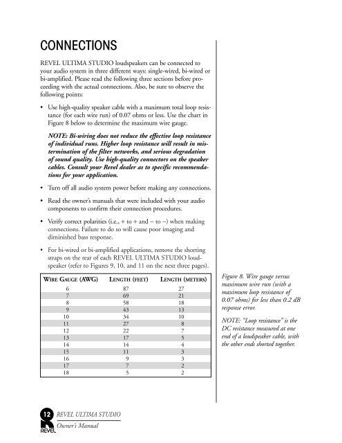
• Use high-quality speaker cable with a maximum total loop resistance<br />
(for each wire run) of 0.07 ohms or less. Use the chart in<br />
Figure 8 below to determine the maximum wire gauge.<br />
NOTE: Bi-wiring does not reduce the effective loop resistance<br />
of individual runs. Higher loop resistance will result in mistermination<br />
of the filter networks, and serious degradation<br />
of sound quality. Use high-quality connectors on the speaker<br />
cables. Consult your <strong>Revel</strong> dealer as to specific recommendations<br />
for your application.<br />
• Turn off all audio system power before making any connections.<br />
• Read the owner’s manuals that were included with your audio<br />
components to confirm their connection procedures.<br />
• Verify correct polarities (i.e., + to + and − to −) when making<br />
connections. Failure to do so will cause poor imaging and<br />
diminished bass response.<br />
• For bi-wired or bi-amplified applications, remove the shorting<br />
straps on the rear of each REVEL ULTIMA STUDIO loudspeaker<br />
(refer to Figures 9, 10, and 11 on the next three pages).<br />
WIRE GAUGE (AWG) LENGTH (FEET) LENGTH (METERS)<br />
6 87 27<br />
7 69 21<br />
8 58 18<br />
9 43 13<br />
10 34 10<br />
11 27 8<br />
12 22 7<br />
13 17 5<br />
14 14 4<br />
15 11 3<br />
16 9 3<br />
17 7 2<br />
18 5 2<br />
12<br />
REVEL ULTIMA STUDIO<br />
Owner’s Manual<br />
Figure 8. Wire gauge versus<br />
maximum wire run (with a<br />
maximum loop resistance of<br />
0.07 ohms) for less than 0.2 dB<br />
response error.<br />
NOTE: “Loop resistance” is the<br />
DC resistance measured at one<br />
end of a loudspeaker cable, with<br />
the other ends shorted together.