
You also want an ePaper? Increase the reach of your titles
YUMPU automatically turns print PDFs into web optimized ePapers that Google loves.
<strong>MC</strong> <strong>Series</strong> User User Manual<br />
Manual<br />
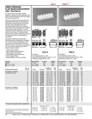
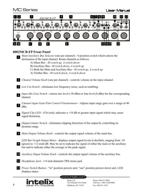
8002<strong>MC</strong>B-FP Front Panel<br />
Main/Auxiliary Bus Selector (one per channel) - 4-position switch which selects <strong>the</strong><br />
1<br />
destination of <strong>the</strong> input channel. Route channels as follows:<br />
A) Main Bus - M switch up, A switch down<br />
B) Auxiliary Bus - M switch down, A switch up<br />
C) Both <strong>the</strong> Main and Auxiliary Bus - M switch up, A switch up<br />
A) Nei<strong>the</strong>r Bus - M switch down, A switch down<br />
8<br />
1 2 3<br />
2<br />
3<br />
4<br />
5<br />
6<br />
7<br />
8<br />
9<br />
10<br />
11<br />
12<br />
8002<strong>MC</strong>B-FP<br />
4 5 6 7<br />
Channel Volume Knob (one per channel) - controls volume on <strong>the</strong> input channel.<br />
Low Cut Switch - eliminates low frequency noise, such as rumbling.<br />
Input Mic/Line Switch - selects mic level (-50 dBu) or line level (0 dBu) <strong>for</strong> <strong>the</strong> corresponding<br />
channel.<br />
Channel Input Gain/Trim Control Potentiometer - Adjusts input stage gain over a range of 40<br />
dBu.<br />
Signal Clip LED - if lit (red), indicates a +18 dB or greater input signal which may cause<br />
signal distortion.<br />
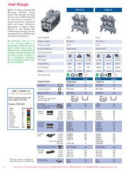
Output Limiter Switch - eliminates clipping distortion of <strong>the</strong> output by controlling its<br />
dynamic range.<br />
Main Output Volume Knob - controls <strong>the</strong> output signal volume of <strong>the</strong> main bus.<br />
LED Bar Graph Output Meter - displays output signal levels in decibels, ranging from -18<br />
(green) to +12 (red) dB. May be set to indicate <strong>the</strong> signal of ei<strong>the</strong>r <strong>the</strong> main or <strong>the</strong> auxiliary<br />
bus and to indicate ei<strong>the</strong>r <strong>the</strong> average or <strong>the</strong> peak signal.<br />
Auxiliary Ouput Volume Knob - controls <strong>the</strong> output signal volume of <strong>the</strong> auxiliary bus.<br />
Headphone Jack - 1/4 inch-diameter TRS mono jack<br />
Power Switch Button - “in” position powers unit; “out” position powers down unit. LED<br />
displays status.<br />
www.intelix.com<br />
8 9 10<br />
A B C D E F<br />
13 14 15 16<br />
Intelix LLC Phone: 608-831-0880<br />
2222 Pleasant View Road Toll-Free: 1-866-4-MATMIX<br />
Middleton, WI 53562 Fax: 608-831-1833<br />
11<br />
12