Manual and spare parts list TAWI HOIST
Manual and spare parts list TAWI HOIST
Manual and spare parts list TAWI HOIST

Create successful ePaper yourself
Turn your PDF publications into a flip-book with our unique Google optimized e-Paper software.
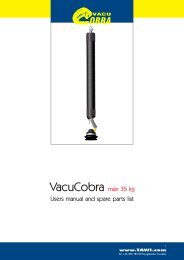
TH80
Contents<br />
Congratulations on your choice of <strong>TAWI</strong> lifting<br />
equipment!<br />
The following pages introduces you to your new<br />
<strong>TAWI</strong> Hoist.<br />
Read this manual carefully before operating.<br />
General description<br />
Installation<br />
User’s Guide<br />
Safety instructions<br />
Exploded view, upper part<br />
Parts <strong>list</strong>, upper part<br />
Exploded view, control device<br />
Parts <strong>list</strong>, control device<br />
Wiring diagram<br />
Declaration of conformity<br />
Check <strong>list</strong><br />
Warranty<br />
Time of warranty is 1 year<br />
from date of delivery.<br />
This warranty covers the replacement<br />
or repair of defect <strong>parts</strong> of the hoist.<br />
The warranty is valid only if original<br />
<strong>spare</strong> <strong>parts</strong> have been used <strong>and</strong> all<br />
instructions of this<br />
manual have been followed.
2. Conduit entry for<br />
manoeuvre cable<br />
4. Wire<br />
5. Emergency stop switch<br />
7. H<strong>and</strong>le<br />
General description<br />
9. Lever<br />
1. Conduit entry<br />
240V50Hz/60Hz<br />
6. Wire attachment<br />
8. Hook attachment<br />
3. Reset switch
Specifications:<br />
General description<br />
1. Power supply 240V50Hz/60Hz.<br />
The hoist can be connected to all electric supply networks with current as <strong>list</strong>ed<br />
above. The power supply must have a 10A fuse.<br />
2. Conduit entry for manoeuvre cable.<br />
The manoeuvre cable is a screened multi conductor cable <strong>and</strong> may not be<br />
replaced with anything but original <strong>parts</strong>.<br />
3. Reset switch.<br />
The reset switch is used to reset the inverter in case of overload, overcurrent,<br />
overvoltage etc.<br />
4. Lifting wire.<br />
May only be replaced with original <strong>spare</strong> <strong>parts</strong>.<br />
5. Emergency stop switch.<br />
Locked by pushing. Released by turning the knob.<br />
6. Wire attachment.<br />
Swivelling attachment. Blocking the swivel will cause serious damage to the wire.<br />
7. H<strong>and</strong>le.<br />
Can be adjusted in height for individual settings.<br />
8. Hook attachment.<br />
Swivelling attachment. Blocking the swivel will cause serious damage to the wire.<br />
9. Lever.<br />
Controls speed <strong>and</strong> direction.<br />
TH80<br />
Max capacity: 80 KGs / 170 LBS.<br />
Dim. upper part: 430 x 280 x 270 (mm)<br />
Power supply: 230V 50/60Hz<br />
Lifting height: 2500 mm<br />
Overall dim.: 890 mm<br />
Velocity: 0,35 m/s<br />
Weight: 18 KGs / 39 LBS.<br />
Speed control: Variable
Installation<br />
Step 1.<br />
Check that the delivery corresponds with the delivery note.<br />
The hoist is delivered fully assembled.<br />
Step 2.<br />
Make sure that the suspension device is approved for minimum 1,5 x maximum<br />
lifting capacity of the hoist.<br />
Step 3.<br />
The hoist is designed to be suspended in two track trolleys. The suspension<br />
chosen must be approved for lifting purposes <strong>and</strong> designed for a maximum<br />
lifting capacity of AT LEAST the weight of the load AND the dead weight of<br />
the hoist.<br />
NOTE! Step 4-5 must be performed by authorised electrician.<br />
Step 4.<br />
Remove the cover from the side of the hoist where the conduit entry is located.<br />
Step 5.<br />
Connect the power supply cable (flat cable is recommended) to the terminal<br />
block (ADO).<br />
Replace the cover. Connect to electric supply network (10A fuse).<br />
THE <strong>HOIST</strong> IS NOW READY TO USE AFTER THE PRELIMINARY<br />
CHECK HAS BEEN PERFORMED.
User’s Guide<br />
Operating instructions:<br />
To start the hoist after a power cut, push the green reset switch once. The hoist<br />
is now ready to operate.<br />
Operating the hoist is accomplished by moving the lever in required direction,<br />
(up/down), the lifting speed is adjusted by means of increasing/decreasing the<br />
angle the lever is moved.<br />
Preliminary check<br />
Check the function of the upper limit switch by running the hoist upwards until<br />
the switch stops the hoist. This switch is to be considered as an emergency stop<br />
switch <strong>and</strong> it should not be used in the daily operation.<br />
When running downwards the wire will stop feeding out automatically when the<br />
load/hook reaches the floor.<br />
The hoist is equipped with an electrically operated break that automatically<br />
breaks the movement when the lever is moved to neutral position.<br />
The break function produces a slight clicking noise, which is normal for this type<br />
of break equipment.<br />
Daily routine checks:<br />
Thoroughly check the lifting wire, fasteners <strong>and</strong> hook for damage <strong>and</strong> wear.<br />
NOTE! Never use the hoist if damage has been found.<br />
Contact your dealer for repair.<br />
Check the function of the emergency stop switch before using the hoist.<br />
Monthly routine checks:<br />
Check all suspensions for sign of wear.<br />
Check the lifting wire for wear <strong>and</strong> damage.<br />
Check the manoeuvre cable for wear <strong>and</strong> damage.<br />
Check that the speed control is working properly during the whole stroke.<br />
Check the function of the emergency switch.<br />
Check the function of the upper limit switch.<br />
NOTE! Never use the hoist if damage is found.<br />
Contact your dealer for repair.
Safety Instructions<br />
To ensure maximum personal safety it is essential to avoid all<br />
incorrect use:<br />
� Do not allow untrained staff to operate the hoist.<br />
� Do not exceed the hoists maximum lifting capacity.<br />
� Never use the hoist for lifting person/persons.<br />
� Never leave load hanging in the hoist.<br />
� Never move or st<strong>and</strong> below hanging load.<br />
� Never use the lifting wire as earth lead when welding.<br />
� Never use the hoist to tow goods on the floor.<br />
� Repairs <strong>and</strong>/or adjustments may only be performed by<br />
authorised personnel.<br />
� Always read the manual carefully before using the hoist.<br />
� Make sure that the load is well balanced before lifting.<br />
Caution!<br />
� Neglect in following the safety instructions may cause<br />
serious bodily harm.<br />
� The operator must be fully trained in h<strong>and</strong>ling the hoist.<br />
� All instructions in this manual must be followed at all times.<br />
� The crane system/suspension unit must be installed by<br />
authorised personnel <strong>and</strong> all safety regulations must be<br />
followed. DO NOT EXCEED max capacity. (Dead weight<br />
of hoist+weight of load).<br />
� Maintenance instructions must be followed <strong>and</strong> only<br />
original <strong>spare</strong> <strong>parts</strong> may be used.<br />
� The suspension must be thoroughly checked on a regular<br />
basis.<br />
� Electrical installations/alterations may only be carried out<br />
by authorised electricians.
Wiring diagram
Exploded view, upper part
Parts List, upper part<br />
ARTICLE NO DESCRIPTION AMOUNT<br />
251000 1 <strong>HOIST</strong> (251088 PG16 1pce, 251089 PG13,5<br />
1pce, 251040 A1507HPL 2pcs included)<br />
No1 251001 1 BODY<br />
No2 251002A 1 ELECTRIC MOTOR / WORM GEAR<br />
No3 251003 1 SLIP PLANE – INNER<br />
No4 251004 1 DRIVING SHAFT<br />
251004-01 1 KEY<br />
No5* 251005 LNM16FLÄNS 1 NUT<br />
251005-01 BRB 17*30 1 WASHER<br />
No6 251006 1 DRUM<br />
No7 251007 FCB35 42x35 L=30 1 ONE WAY BEARING<br />
No8 251008 1 SLIP PLANE OUTER<br />
No9 251009 MELC6S M10*12 1 SCREW<br />
No10 251010 1 SLIP PLANE<br />
No11 251011 1 SPRING<br />
No12 251012 1 HOUSING<br />
No13 251013 1 COVER<br />
251013-01 1 COVER<br />
251013-02 1 CARRIER<br />
No14 251014 MC6S M6*20 6 SCREW<br />
No15 251015 MF6S M8*25 6 SCREW<br />
No16 251016 LNM8 8 NUT<br />
No17 251017 MC6PSM6 8*25 1 BEARING BOLT<br />
No18 251018 1 LEVER<br />
No19 251019 1 SPRING<br />
No20 251020 MC6S M6*30 1 SCREW<br />
No21 251021 M6 MUTTER 1 NUT<br />
No22 251022 BRB 6.5*11 1 WASHER<br />
No23 251023 1 PLATE<br />
No24 251024 MC6S M4*10 2 SCREW<br />
No25 251025 BZ 2RW822 A2 2 MICROSWITCH<br />
No26 251026 MC6S M3*40 2 SCREW<br />
No27 251027 STOPPSKRUV 1 STOPPING DEVICE<br />
M4*25<br />
No28 251028 M4 MUTTER 1 NUT<br />
No29 251029A 1 FREQUENCY CONTROL UNIT<br />
No30 251030 B=35 L=20 1 BRACKET<br />
No31 251031 M4/9 24VDC<br />
2 RELAY<br />
1POL.SL.IND<br />
No32 251032 MC6S M4*15 4 SCREW<br />
No33 251033 MC6S M5*8 2 SCREW<br />
No34 251034/2007 2 CONDUIT ENTRY MANOEUVRE<br />
No35 251035 1 CONDUIT ENTRY POWER SUP.<br />
No36 251036 1 BRACKET<br />
No37 251037 1 RESET SWITCH<br />
251037-01 C23AD02 1 PUSH BUTTON<br />
252005-02 230E/23E10 1 SWITCH<br />
251037-05 1 FASTENER<br />
No38 251038-01 1 SUSPENSION<br />
251038-02 1 SUSPENSION
Parts List, upper part<br />
251039 MF6S M8*20 2 SCREW<br />
251040 A1507HPL 2<br />
No41 251041-01 2 COVER BRACKET<br />
251041-02 2 COVER BRACKET<br />
No42 251042 SgA 20 8 CLAMP RING<br />
No43 251084 DIA.=3 6*19 1 WIRE<br />
No44 251044 2 WIRE LOCK<br />
No45 251045 1 RIM<br />
No46 251046 1 COVER - MOTORSIDE<br />
No47 251047 1 COVER - WIRESIDE<br />
No48 251048 8 SCREW<br />
No49 251049 BRB 4.5*19 2 WASHER<br />
No50 251050 19*35*38.3 1 SPACING SLEEVE<br />
No51 251051 8*260 RF 1 SPRING<br />
No52 251052 1 MANOEUVRE CABLE<br />
No53 251053 49984 1 CLAMP<br />
No54 251054 MOTOR 1 CABLE - ELECTRIC MOTOR<br />
No55 251055 KRAFT/RESET 1 CABLE - POWER SUP. / RESET<br />
No56 251056 MANÖVER 1 CABLE - MANOEUVRE<br />
No57 251057 1 TERMINAL BLOCK<br />
No58 251058 1 TERMINAL BLOCK - POWER SUP.<br />
No59 251059 1<br />
No60 251060 5<br />
No61 251061 RELÄ 1 CABLE-RELAY<br />
No62 251062 BROMS 1 CABLE-BREAK<br />
251063 STOPPER 1<br />
251064 CABLE 1<br />
251068 CABLE 0,5M<br />
251071 RING CABLE CLIP 3 4MM<br />
251072 RING CABLE CLIP 4 5MM<br />
251077 CABLE 0,5M<br />
251079 BUNDLERS 2 145/3<br />
251080 BUNDLERS 1 285/5<br />
251088 Pg16 1<br />
251089 Pg13,5 1<br />
251091 BRACKET 1<br />
251093 CAGING 1<br />
251094 SCREW 2 MC6S M5*16 FZB<br />
251097 NUT 2 M16 FZB<br />
8SPR310 WASHER DIN9021 2 3,2X9X0,8<br />
8SPR816 WASHER 4 8,4X16X1,5
Exploded view,<br />
h<strong>and</strong><br />
control
Parts List, h<strong>and</strong> control<br />
ARTICLE NO DESCRIPTION AMOUNT<br />
252000 1 <strong>HOIST</strong> CONTROL DEVICE<br />
No1 252001 1 TOP BRACKET<br />
No2 252002 1 WIRE ATTACHMENT<br />
No3 252003 AXK1226 2 BEARING<br />
No4 252004 1 E.S. BRACKET<br />
No31 251033 MC6S M5*8 2 SCREW<br />
No5 252005 1 EMERGENCY STOP<br />
SWITCH<br />
252005-01 C21EC01 1 PUSH BUTTON<br />
252005-02 230E/23E01 1 SWITCH<br />
No6 252006 M5*185 4 TIE ROD<br />
No32 251034 0(1) CONDUIT ENTRY<br />
No8 252008 PUR RAL 5005 1 COVER<br />
No9 252009 LN M5 8 LOCKNUT<br />
No10 252010 1 BODY<br />
No11 252011 M6 2 NUT<br />
No12 252012 1 HANDLE<br />
No13 252013 MC6S M6*30 2 SCREW<br />
No14 252014 1 BOTTOM BRACKET<br />
No15 252015 1 HOOK ATTACHMENT<br />
No16 252016 1 MOUNTING PLATE<br />
No17 252017 48-355-59 0.5 TERMINAL BLOCK<br />
No18 252018 ET 114 25 GRADER 1 THROTTLE<br />
No19 252019 1 STOP CLEAT<br />
No20 252020 MF6S M5*20 2 SCREW<br />
No21 252021 1 SPRING<br />
No22 252022 1 CARRIER<br />
No23 252023 2 LEVER BRACKET<br />
No24 252024 1 LEVER<br />
No25 252025 M3*6 1 SCREW<br />
No26 252026 MF6S M4*12 2 SCREW<br />
No27 252027 BHGS 5/6 1 HOOK<br />
No28 252028 1 SCHACKLE<br />
No29 252029 MF6S M3*12 2 SCREW<br />
No30 252030 mc6s m3*15 2 SCREW<br />
252036 PLASTIC WASHER 2 FOR WIRE BRACKET
ASSURANCE ABOUT COMPLIANCE<br />
Manufacturer: <strong>TAWI</strong> AB<br />
Company<br />
Box 10205, S-434 23 KUNGSBACKA SWEDEN<br />
Address<br />
Representative:<br />
Company<br />
Address<br />
Description of Machine: TawiHoist TH80 Serial No…………<br />
Make, type, serial number or similar<br />
Regulation: Machine Directive AFS 1994:48 (98/37/EC)<br />
Testing authority: SAQ Kontroll AB<br />
(where appropriate) Company<br />
Box 49306, 100 29 Stockholm<br />
Address<br />
Authority has: EC approved certificate no:SA Q M100-99<br />
Received documentation according to enclosure 6 of the Directive <strong>and</strong><br />
verified the correct use of st<strong>and</strong>ards <strong>and</strong> the accuracy of the<br />
documentation.<br />
St<strong>and</strong>ards: EN 292-1, EN 292-2<br />
(where appropriate)<br />
We hereby certify that the machine described in this document<br />
has been manufactured in accordance with EC Machine<br />
Directive 89/392<strong>and</strong> addendum; further, where appropriate, is in<br />
accordance with the machine that was EC approved by above<br />
Testing Authority.<br />
Kungsbacka,<br />
Place - date<br />
Name<br />
<strong>TAWI</strong> AB<br />
Company
Check<strong>list</strong><br />
Model TH80<br />
� TH80 – Tested with 85 KGs weight. �<br />
� Check reset knob �<br />
� Manouvre h<strong>and</strong>le correct assembled �<br />
� Check emergency stop button �<br />
� Wire correct connected �<br />
� Top micro switch – check function �<br />
� Check that all bolts/nuts are sufficiently tightened. �<br />
� Lubricate the driveshaft <strong>and</strong> the one-way bearing when assembling. �<br />
� Lubricate all bearings. �<br />
� Programme the inverter. �<br />
� Perform a running/function test on the hoist. �<br />
� Make sure that the hoist does not produce any unwanted noise. �<br />
� Check the function of the upper limit switch. �<br />
� Make sure that all labels are in place <strong>and</strong> with instructions in correct<br />
language. �<br />
� Wipe the hoist clean <strong>and</strong> prepare it for delivery. �<br />
Kungsbacka<br />
Place Date<br />
Name<br />
Serial No.