WFD Series Waterflow Detector - System Sensor
WFD Series Waterflow Detector - System Sensor
WFD Series Waterflow Detector - System Sensor

You also want an ePaper? Increase the reach of your titles
YUMPU automatically turns print PDFs into web optimized ePapers that Google loves.
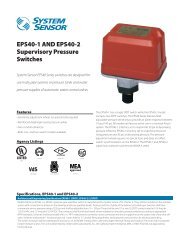
<strong>WFD</strong> <strong>Series</strong><br />
<strong>Waterflow</strong> <strong>Detector</strong><br />
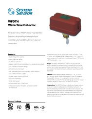
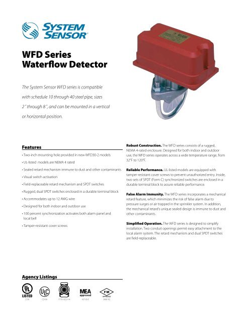
The <strong>System</strong> <strong>Sensor</strong> <strong>WFD</strong> series is compatible<br />
with schedule 10 through 40 steel pipe, sizes<br />
2˝ through 8˝, and can be mounted in a vertical<br />
or horizontal position.<br />
Features<br />
• Two-inch mounting hole provided in new <strong>WFD</strong>30-2 models<br />
• UL-listed models are NEMA 4 rated<br />
• Sealed retard mechanism immune to dust and other contaminants<br />
• Visual switch activation<br />
• Field-replaceable retard mechanism and SPDT switches<br />
• Rugged, dual SPDT switches enclosed in a durable terminal block<br />
• Accommodates up to 12 AWG wire<br />
• Designed for both indoor and outdoor use<br />
• 100 percent synchronization activates both alarm panel and<br />
local bell<br />
• Tamper-resistant cover screws<br />
Agency Listings<br />
S739<br />
CS169<br />
7770-1653:114 167-93-E<br />
3006195<br />
Robust Construction. The <strong>WFD</strong> series consists of a rugged,<br />
NEMA 4-rated enclosure. Designed for both indoor and outdoor<br />
use, the <strong>WFD</strong> series operates across a wide temperature range, from<br />
32°F to 120°F.<br />
Reliable Performance. UL-listed models are equipped with<br />
tamper-resistant cover screws to prevent unauthorized entry. Inside,<br />
two sets of SPDT (Form C) synchronized switches are enclosed in a<br />
durable terminal block to assure reliable performance.<br />
False Alarm Immunity. The <strong>WFD</strong> series incorporates a mechanical<br />
retard feature, which minimizes the risk of false alarm due to<br />
pressure surges or air trapped in the sprinkler system. In addition,<br />
the mechanical retard’s unique sealed design is immune to dust and<br />
other contaminants.<br />
Simplified Operation. The <strong>WFD</strong> series is designed to simplify<br />
installation. Two conduit openings permit easy attachment to the<br />
local alarm system. The retard mechanism and dual SPDT switches<br />
are field-replaceable.
<strong>Waterflow</strong> <strong>Detector</strong> Specifications<br />
Engineering Specifications<br />
Vane-type waterflow detectors shall be installed on system piping as designated on the drawing and/or as specified herein. <strong>Detector</strong>s shall mount on any<br />
clear pipe span of the appropriate nominal size, either a vertical upflow or horizontal run, at least 6˝ from any fittings that may change water direction,<br />
flow rate, or pipe diameter or no closer than 24˝ from a valve or drain. <strong>Detector</strong>s shall have a sensitivity in the range of 4 to 10 gallons per minute and a<br />
static pressure rating of 450 psi* for 2˝ – 8˝ pipes. The detector shall respond to waterflow in the specified direction after a preset time delay that is field<br />
adjustable. The delay mechanism shall be a sealed mechanical pneumatic unit with visual indication of actuation. The actuation mechanism shall include<br />
a polyethylene vane inserted through a hole in the pipe and connected by a mechanical linkage to the delay mechanism. Outputs shall consist of dual<br />
SPDT switches (Form C contacts). Two conduit entrances for standard fittings of commonly used electrical conduit shall be provided on the detectors.<br />
A grounding provision is provided. Unless noted, enclosures shall be NEMA 4 listed by Underwriters Laboratories Inc. All detectors shall be listed by<br />
Underwriters Laboratories Inc. for indoor or outdoor use.<br />
Standard Specifications<br />
Static Pressure Rating 450 PSI* Operating Temperature Range 32°F to 120°F (0°C to 49°C)<br />
Maximum Surge 18 Feet Per Second (FPS) Enclosure Rating* NEMA 4 – suitable for indoor/outdoor use<br />
Triggering Threshold 4–10 GPM Cover Tamper Switch Standard with ULC models, optional for UL<br />
Bandwidth (Flow Rate)<br />
models, part no. 546-7000<br />
Conduit Entrances Two openings for ½˝ conduit.<br />
Service Use Automatic Sprinkler: NFPA-13<br />
One open, one knock-out type<br />
One or Two Family Dwelling: NFPA 13D<br />
Residential Occupancies up to 4 Stories: NFPA 13R<br />
National Fire Alarm Code: NFPA-72<br />
Contact Ratings Two sets of SPDT (Form C)<br />
10.0 A, ½ HP @ 125/250 VAC<br />
2.5 A @ 6/12/24 VDC<br />
U.S. Patent Numbers 5,213,205<br />
Compatible Pipe Steel water pipe, schedule 10 through 40 Warranty 3 Years<br />
<strong>WFD</strong> Field Wiring Diagram<br />
UL-LISTED<br />
COMPATIBLE<br />
CONTROL PANEL<br />
POWER +<br />
24VDC OR<br />
120VDC –<br />
INITIATING<br />
LOOP<br />
+<br />
–<br />
SUGGESTED EOL<br />
RESISTOR<br />
SSM24-X<br />
SSV120-X<br />
NOTE: COMMON AND B-NO<br />
CONNECTIONS WILL CLOSE<br />
WHEN VANE IS DEFLECTED, I.E.,<br />
WHEN WATER IS FLOWING. DUAL<br />
SWITCHES PERMIT<br />
APPLICATIONS TO BE COMBINED<br />
ON A SINGLE DETECTOR.<br />
CONTACT RATINGS<br />
125/250 VAC<br />
24 VDC<br />
10 AMPS<br />
2.5 AMPS<br />
SCHEMATIC OF<br />
INDIVIDUAL<br />
SWITCH IN<br />
“NO WATERFLOW”<br />
CONDITION<br />
BREAK WIRE AS<br />
SHOWN FOR<br />
SUPERVISION OF<br />
CONNECTION. DO<br />
NOT ALLOW<br />
STRIPPED WIRE<br />
LEADS TO EXTEND<br />
BEYOND SWITCH<br />
HOUSING. DO NOT<br />
LOOP WIRES.<br />
A-NC<br />
COM<br />
B-NO<br />
Delay Adjustment Dial<br />
DELAY<br />
ADJUSTMENT<br />
DIAL<br />
TIME DELAY IN SECONDS<br />
NUMBER ON DIAL IS APPROXIMATE<br />
15<br />
30<br />
55<br />
3825 Ohio Avenue • St. Charles, IL 60174<br />
Phone: 800-SENSOR2 • Fax: 630-377-6495<br />
0<br />
45<br />
NOTE: RETARD TIME MAY EXCEED 90 SECONDS. ADJUST<br />
AND VERIFY THAT TIME DOES NOT EXCEED 90 SECONDS.<br />
NUMBER ON DIAL IS APPROXIMATE TIME DELAY IN<br />
SECONDS WITH AN ACCURACY OF +/− 50%.<br />
Ordering Information<br />
UL Model ULC Model Pipe Size Hole Size Shipping Weight<br />
<strong>WFD</strong>20 <strong>WFD</strong>20A 2˝ 1¼˝ 4.2 lbs.<br />
<strong>WFD</strong>25 <strong>WFD</strong>25A 2½˝ 1¼˝ 4.3 lbs.<br />
<strong>WFD</strong>30-2 <strong>WFD</strong>30-2A 3˝ 2˝ 4.5 lbs.<br />
<strong>WFD</strong>35 <strong>WFD</strong>35A 3½˝ 1¼˝ 4.7 lbs.<br />
<strong>WFD</strong>40 <strong>WFD</strong>40A 4˝ 2˝ 5.2 lbs.<br />
<strong>WFD</strong>50 <strong>WFD</strong>50A 5˝ 2˝ 6.3 lbs.<br />
<strong>WFD</strong>60* <strong>WFD</strong>60A 6˝ 2˝ 6.8 lbs.<br />
<strong>WFD</strong>80*<br />
Accessories<br />
<strong>WFD</strong>80A 8˝ 2˝ 7.5 lbs.<br />
A3008-00 Retard mechanism<br />
A77-01-02 Terminal block<br />
546-7000 Tamper-proof switch kit<br />
<strong>WFD</strong>W Tamper-proof wrench for cover<br />
<strong>WFD</strong>N4 Gasket kit<br />
*Maximum pressure rating 400 psi as approved by Factory Mutual.<br />
70<br />
Overall Dimensions, Installed<br />
U bolt nut<br />
Pipe saddle<br />
U bolt<br />
3.0″<br />
3.75″<br />
Width: See Table<br />
Model<br />
<strong>WFD</strong>20<br />
<strong>WFD</strong>25<br />
<strong>WFD</strong>30-2<br />
<strong>WFD</strong>35<br />
Pipe<br />
Plastic vane<br />
©2009 <strong>System</strong> <strong>Sensor</strong>.<br />
Product specifications subject to change without notice. Visit systemsensor.com for<br />
current product information, including the latest version of this data sheet.<br />
A05-0180-013 • 1/09 • #1922<br />
1.6″<br />
Width<br />
4.6″<br />
4.6″<br />
5.2″<br />
5.7″<br />
Model<br />
<strong>WFD</strong>40<br />
<strong>WFD</strong>50<br />
<strong>WFD</strong>60<br />
<strong>WFD</strong>80<br />
Width<br />
6.8″<br />
7.8″<br />
9.0″<br />
10.8″