Fluxless laser beam joining of aluminium with zinc coated steel
Fluxless laser beam joining of aluminium with zinc coated steel
Fluxless laser beam joining of aluminium with zinc coated steel

Create successful ePaper yourself
Turn your PDF publications into a flip-book with our unique Google optimized e-Paper software.
<strong>Fluxless</strong> <strong>laser</strong> <strong>beam</strong> <strong>joining</strong> <strong>of</strong> <strong>aluminium</strong> <strong>with</strong><br />
<strong>zinc</strong> <strong>coated</strong> <strong>steel</strong><br />
H. Laukant 1 , C. Wallmann 1 ,M.Müller 1 , M. Korte 2 , B. Stirn 2 ,<br />
H.-G. Haldenwanger 2 and U. Glatzel* 1<br />
A <strong>laser</strong> welding–brazing (LWB) process to join <strong>zinc</strong> <strong>coated</strong> <strong>steel</strong> and <strong>aluminium</strong> sheets in two<br />
different flange geometries is reported. The deep drawing <strong>steel</strong> sheets are covered by a <strong>zinc</strong> layer<br />
<strong>of</strong> maximum thickness 10 mm, and a <strong>zinc</strong> based filler wire was used in the welding experiments<br />
<strong>with</strong> a Nd–YAG <strong>laser</strong>. Because <strong>of</strong> the differences in melting temperatures between iron (1808 K),<br />
<strong>aluminium</strong> (933 K), and <strong>zinc</strong> (693 K), it is possible to weld the <strong>aluminium</strong> alloy only. Owing to the<br />
<strong>zinc</strong> coating on the <strong>steel</strong> side, a Zn–Al alloy can be brazed onto the <strong>steel</strong> <strong>with</strong>out any flux agent.<br />
The inevitable formation <strong>of</strong> a Fe–Al intermetallic phase at the bondline <strong>of</strong> the weld seam and the<br />
<strong>steel</strong> can be limited to a thickness <strong>of</strong> less than 5 mm and to a proportion <strong>of</strong> the contact area only.<br />
Mechanical as well as dynamic tests show results comparable to those obtained via other <strong>joining</strong><br />
techniques. Salt chamber corrosion tests <strong>of</strong> varnished specimens display minor damage and no<br />
decline in tensile strength.<br />
Keywords: Laser welding–brazing process, Zinc <strong>coated</strong> <strong>steel</strong> sheet, Aluminium sheet, Zn–Al alloy, Fe–Al intermetallic phase, Corrosion, Tensile<br />
strength<br />
Introduction<br />
Owing to the demand for lightweight structures there is<br />
increasing interest in the automobile industry in<br />
substituting <strong>steel</strong> <strong>with</strong> lighter materials, <strong>with</strong>out completely<br />
excluding it. Such mixed material constructions,<br />
involving the use <strong>of</strong> dissimilar metals, will require major<br />
changes in automotive body construction. With regard<br />
to hybrid structures, techniques for <strong>joining</strong> dissimilar<br />
metals must be improved or newly developed.<br />
Conventional methods <strong>of</strong> <strong>joining</strong> dissimilar metals<br />
include mechanical <strong>joining</strong> <strong>with</strong> rivets, clinches,<br />
or screws, adhesive bonding, and various welding<br />
methods. 1–18 Among thermal <strong>joining</strong> techniques suitable<br />
for metallurgically incompatible materials, the <strong>laser</strong><br />
welding process in particular has the advantage <strong>of</strong> short<br />
process times and one sided access to the <strong>joining</strong> zone.<br />
Hence it <strong>of</strong>fers good adaptability and a desirable<br />
relationship between weight reduction and costs in serial<br />
production. To the present authors’ knowledge, for the<br />
combination <strong>of</strong> <strong>aluminium</strong> and <strong>steel</strong>, there exists no<br />
<strong>laser</strong> <strong>beam</strong> <strong>joining</strong> technique that can join these two<br />
materials in their liquid phase because <strong>of</strong> the formation<br />
<strong>of</strong> hard and brittle intermetallic phases <strong>with</strong>in the Fe–Al<br />
melt. 1,10 As these intermetallic phases act similarly to<br />
metallurgical cracks <strong>with</strong>in the weld line, they limit the<br />
mechanical properties and especially the fatigue strength<br />
<strong>of</strong> such joints. In previous work a new <strong>laser</strong> <strong>beam</strong><br />
1 University <strong>of</strong> Bayreuth, Metals and Alloys, Ludwig-Thoma-Str. 36b, D–<br />
95447 Bayreuth, Germany<br />
2 Audi AG, D–85045 Ingolstadt, Germany<br />
*Corresponding author, email Uwe.glatzel@uni-bayreuth.de<br />
<strong>joining</strong> technique was developed in which the <strong>laser</strong> is<br />
directed onto the <strong>steel</strong> sheet, melting and brazing the<br />
<strong>aluminium</strong> through heat conduction. 1,2 However, this<br />
process was conducted on <strong>steel</strong> sheets <strong>with</strong>out a <strong>zinc</strong><br />
coating and a flux was used to promote the wetting and<br />
brazing <strong>of</strong> the <strong>steel</strong>. Riveting is also a common and well<br />
researched process to join mixed material constructions.<br />
4,11 Some <strong>of</strong> the disadvantages <strong>of</strong> riveting in<br />
automobile construction are a slower assembly cycle,<br />
the limitation that only overlapping geometries can be<br />
joined, and the undesirability <strong>of</strong> using this <strong>joining</strong><br />
technique in automotive body shell parts owing to the<br />
visibility <strong>of</strong> the rivet. However, in combination <strong>with</strong><br />
adhesive bonding and <strong>coated</strong> self-piercing rivets, this<br />
dissimilar material <strong>joining</strong> technique has the advantage<br />
<strong>of</strong> averting galvanic corrosion by preventing intrusion <strong>of</strong><br />
an electrolyte. 18<br />
In the present paper a <strong>laser</strong> welding–brazing (LWB)<br />
process is presented that allows the <strong>joining</strong> <strong>of</strong> <strong>zinc</strong> plated<br />
<strong>steel</strong> and <strong>aluminium</strong> sheets using a <strong>zinc</strong> based filler alloy.<br />
The joint has a dual characteristic and is divided into a<br />
welding part on the <strong>aluminium</strong> side, and a brazing part<br />
on the <strong>steel</strong> side. The process itself can be carried out<br />
<strong>with</strong>out any brazing flux agent owing to the similar<br />
materials used for the <strong>zinc</strong> coating and filler alloy as well<br />
as the miscibility <strong>of</strong> <strong>aluminium</strong> in <strong>zinc</strong>. Since car<br />
manufacturers mainly use <strong>zinc</strong> <strong>coated</strong> <strong>steel</strong> sheets for<br />
car bodies, the Zn–Al filler wire enables sufficient<br />
wetting <strong>of</strong> the <strong>steel</strong> to be achieved <strong>with</strong>out an extra flux<br />
agent. This is beneficial since any remaining flux would<br />
have a negative influence on the subsequent application<br />
<strong>of</strong> a base coating, or would have to be removed in an<br />
additional working process. During the <strong>joining</strong> <strong>of</strong> both<br />
ß 2005 Institute <strong>of</strong> Materials, Minerals and Mining<br />
Published by Maney on behalf <strong>of</strong> the Institute<br />
Received 26 April 2004; accepted 27 May 2004<br />
DOI 10.1179/174329305X37051 Science and Technology <strong>of</strong> Welding and Joining 2005 VOL 10 NO 2 219
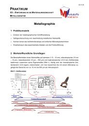
1 Geometry and dimensions (mm) <strong>of</strong> a filled overlap weld<br />
(FOW) and b filled flange (FF) tensile test specimens<br />
metals the temperatures must be kept well below the<br />
melting point <strong>of</strong> iron to prevent or at least limit the<br />
growth <strong>of</strong> an Fe–Al intermetallic layer on the interface<br />
between the <strong>steel</strong> sheet and the <strong>aluminium</strong> rich weld<br />
seam. This can be acheived using the LWB process.<br />
Experimental setup<br />
Materials used<br />
Deep drawing sheets <strong>of</strong> hot dip galvanised DX56DzZ<br />
140MB and electrolytic galvanised DC04zZE 75/75<br />
<strong>steel</strong>s <strong>with</strong> a thickness <strong>of</strong> 0.9 mm, and sheets <strong>of</strong> a rapidly<br />
hardening Al–Mg–Si alloy <strong>of</strong> EN AW–AA6016 type<br />
<strong>with</strong> a thickness <strong>of</strong> 1.1 mm, were used in all welding<br />
experiments. Mechanical properties for the <strong>steel</strong> and<br />
<strong>aluminium</strong> sheets are given in Table 1. The <strong>aluminium</strong><br />
sheets are in the non-cured state (T4) when welded<br />
whereas most <strong>of</strong> the tests were conducted on cured<br />
specimens <strong>with</strong> the <strong>aluminium</strong> sheets in the T6 heat<br />
treatment condition. The transition from T4 to T6<br />
occurs via heat treatment for 20 min at 458 K in the<br />
paint bake process. The dimensions <strong>of</strong> the sheets were<br />
1156200 mm unless specified otherwise. The filler wire<br />
used consists <strong>of</strong> <strong>zinc</strong> <strong>with</strong> 2 wt-%Al (ZnAl2) which<br />
imparts the necessary flexibility to the wire. The surfaces<br />
<strong>of</strong> both metal plates were cleaned using acetone before<br />
welding to remove any surface contamination.<br />
Cross-sectional structure<br />
Cross-sectional specimens taken from welded sheets, at<br />
least 20 mm away from the start and the end <strong>of</strong> the weld<br />
seam, were prepared for optical and electron microscopy<br />
using standard procedures such as polishing, grinding,<br />
and etching. Microstructural and chemical composition<br />
examinations were carried out using a Jeol scanning<br />
electron microscope (SEM) and a Philips CM20<br />
transmission electron microscope (TEM) equipped <strong>with</strong><br />
a field emission gun. Both electron microscopes are<br />
equipped <strong>with</strong> an energy dispersive X-ray (EDX) detector.<br />
For thinning and extraction <strong>of</strong> the TEM sample<br />
an FEI Company Strata DualBeam 235M SEM <strong>with</strong><br />
a focused ion <strong>beam</strong> was used. Using the focused gallium<br />
ion <strong>beam</strong> it is possible to remove material very precisely<br />
from the area <strong>of</strong> interest and to prepare a TEM lamella<br />
having a thickness <strong>of</strong> about 150 nm.<br />
Mechanical and dynamic testing<br />
The specimens in the present work were welded in two<br />
different geometries, namely, a filled flange (FF) and a<br />
filled overlap weld (FOW). Details can be seen in Fig. 1.<br />
The tensile tests on the joints were performed using a<br />
Zwick 100 testing machine equipped <strong>with</strong> a 100 kN load<br />
cell. Deformation speed was set to 10 mm min 21 . Five<br />
specimens from two separately welded sheets were<br />
tensile tested and the results have been averaged. The<br />
average measured maximum forces and elongations are<br />
presented. If tensile stress values are <strong>of</strong> interest the force<br />
must be divided by the cross-sectional area <strong>of</strong> the<br />
<strong>aluminium</strong> sheet (49.5 mm 2 ) or the area <strong>of</strong> the <strong>steel</strong> sheet<br />
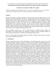
(40.5 mm 2 ) in the tensile test specimen. Cyclic tests were<br />
performed on a specimen <strong>with</strong> six stepped welds to<br />
simulate multiaxial loads and fusion penetrations using<br />
a Rumul Testronic 8601 resonance pulser equipped <strong>with</strong><br />
a 150 kN load cell. The geometry and the location <strong>of</strong> the<br />
stepped welds are shown in Fig. 2. The Vickers hardness<br />
Table 1 Mechanical properties <strong>of</strong> <strong>steel</strong> and <strong>aluminium</strong> sheets used in welding experiments (average <strong>of</strong> 10 specimens)<br />
Sheet material Type t, mm YS, MPa TS, MPa Elongation, %<br />
Steel DX56zZ 140MB 0.9 164 290 44<br />
Steel DC04zZE 75/75 0.9 167 296 43<br />
Aluminium AA6016–T4 1.1 131 244 27<br />
Aluminium AA6016–T6 1.1 170 258 23<br />
t sheet thickness; YS 0.2% yield strength; TS tensile strength.<br />
Laukantetal. <strong>Fluxless</strong> <strong>laser</strong> <strong>beam</strong> <strong>joining</strong> <strong>of</strong> Al <strong>with</strong> Zn <strong>coated</strong> <strong>steel</strong><br />
2 Geometry and dimensions (mm) <strong>of</strong> dynamic test specimens<br />
<strong>with</strong> six stepped welds <strong>of</strong> length 50 mm for a FF<br />
and b FOW joint<br />
Science and Technology <strong>of</strong> Welding and Joining 2005 VOL 10 NO 2 220
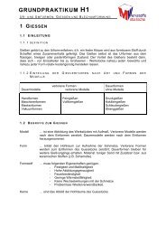
3 a <strong>laser</strong> welding configuration, b clamping device (FOW), and c clamping device (FF)<br />
distribution was measured <strong>with</strong> a semiautomatic Vickers<br />
microhardness tester (Leco Instruments, M 400–A) to<br />
determine a hardness matrix for the joint and the nearby<br />
sheet material.<br />
The LWB process was conducted using a 4.4 kW<br />
diode pumped Nd–YAG <strong>laser</strong> (R<strong>of</strong>in–Sinar DY044)<br />
connected to a two axis linear handling device. The <strong>laser</strong><br />
<strong>beam</strong> was guided through a glass fibre <strong>with</strong> 600 mm<br />
diameter to the weld area and focused using 200 or<br />
120 mm focal length optics depending on the weld<br />
geometry. Owing to the low vaporisation temperature <strong>of</strong><br />
<strong>zinc</strong> (1180 K) metal vapour is released during the<br />
welding process. It was discovered that this vapour,<br />
originating from the filler wire and the <strong>zinc</strong> cover, has an<br />
influence on the quality and stability <strong>of</strong> the process if it<br />
enters the <strong>laser</strong> <strong>beam</strong>. The energy loss into the metal<br />
fumes and the resulting defocus <strong>of</strong> the <strong>beam</strong> lead to<br />
irregular weld seams and a progressive loss <strong>of</strong> strength<br />
<strong>of</strong> the joint from the start to the end <strong>of</strong> the weld seam<br />
<strong>with</strong>in a single sheet. This effect was caused by the<br />
increasing accumulation <strong>of</strong> the released metal vapour in<br />
the <strong>laser</strong> <strong>beam</strong> during the welding process. By employing<br />
a ‘dragging’ position <strong>of</strong> the coaxial filler wire and inert<br />
gas nozzle used as shown in Fig. 3, the emerging vapour<br />
Table 2 Parameters <strong>of</strong> <strong>laser</strong> welding–brazing (LWB) process<br />
Geometry<br />
Focal<br />
length,<br />
mm<br />
Welding<br />
speed,<br />
m min 21<br />
Output<br />
power, W<br />
Laser<br />
angle a<br />
plume can be removed immediately from the <strong>laser</strong> <strong>beam</strong><br />
while the inert gas provides effective shielding <strong>of</strong> the<br />
weld seam. This shielding is essential since oxygen reacts<br />
aggressively <strong>with</strong> the molten <strong>aluminium</strong> as well as the<br />
molten <strong>zinc</strong>, leading to fused on spatters and an<br />
unacceptable welding result. The flowrate <strong>of</strong> shielding<br />
gas was set to 15–25 L min 21 . Welding parameters for<br />
both geometries <strong>of</strong> the LWB process are given in Table 2.<br />
Results and discussion<br />
Cross-sectional structure<br />
Figures 4 and 5 show SEM images <strong>of</strong> the resulting<br />
<strong>joining</strong> zones. It can be seen that the process temperature<br />
in both joints did not reach the melting point <strong>of</strong><br />
<strong>steel</strong>, but did reach that <strong>of</strong> <strong>aluminium</strong>. Therefore the<br />
result is a welded <strong>aluminium</strong> mixture <strong>with</strong> the <strong>zinc</strong> filler<br />
wire, and brazing <strong>of</strong> the <strong>steel</strong> to the in situ formed Zn–Al<br />
alloy.<br />
The measured compositions, verified via EDX analysis<br />
on 10 different points, are very homogeneous and<br />
consist <strong>of</strong> Zn–23 wt-%Al (FOW) and Zn–16 wt-%Al<br />
(FF). Measured values differ only <strong>with</strong>in a range <strong>of</strong><br />
1 wt-% <strong>with</strong>in the weld lines, owing to the intense<br />
Nozzle<br />
angle b<br />
Wire<br />
feedrate,<br />
m min 21<br />
FF 120 0.5–1.5 1400–1800 10–20u 30–40u 2.0–3.5<br />
FOW 200 0.5–1.5 1000–1600 10–20u 30–40u 1.0–2.5<br />
Laukantetal. <strong>Fluxless</strong> <strong>laser</strong> <strong>beam</strong> <strong>joining</strong> <strong>of</strong> Al <strong>with</strong> Zn <strong>coated</strong> <strong>steel</strong><br />
Position <strong>of</strong><br />
<strong>laser</strong> spot<br />
Centre <strong>of</strong><br />
flanges<br />
0–1 mm<br />
from edge<br />
on Al sheet<br />
Focal point,<br />
mm<br />
(210)–(22)<br />
(22)–(z8)<br />
Science and Technology <strong>of</strong> Welding and Joining 2005 VOL 10 NO 2 221
4 Macrostructure <strong>of</strong> LWB joint in FOW geometry: edge<br />
<strong>of</strong> <strong>aluminium</strong> sheet before welding process and area<br />
where intermetallic layer is formed are indicated (SEM)<br />
agitation and mixing in the molten pool during the<br />
<strong>joining</strong> process. The dilution strongly depends on the<br />
amount <strong>of</strong> molten <strong>aluminium</strong> from the <strong>aluminium</strong> sheet.<br />
Therefore the compositions given depend on positioning<br />
and output power <strong>of</strong> the <strong>laser</strong>. For the FOW geometry,<br />
the <strong>laser</strong> <strong>beam</strong> was directed at the <strong>aluminium</strong> sheet.<br />
Hence the weld seam formed is <strong>aluminium</strong> rich. In the<br />
FF geometry the <strong>laser</strong> is positioned between the two<br />
flanges and a smaller amount <strong>of</strong> the <strong>aluminium</strong> sheet is<br />
melted. The intermetallic layers are in both geometries<br />
limited to a small area where the <strong>laser</strong> transfers the<br />
highest energy (due to the Gaussian <strong>laser</strong> power<br />
distribution) into the <strong>steel</strong>. The intermetallic layers<br />
exhibit a maximum thickness <strong>of</strong> 5 mm and hence are<br />
below the critical thickness <strong>of</strong> 10 mm reported in Refs. 1<br />
and 10.<br />
In regions where the <strong>laser</strong> <strong>beam</strong> partially melts the<br />
<strong>steel</strong> surface, the intermetallic layer is highly evident<br />
(see Fig. 6). However, such fusion penetrations could<br />
only be detected in the FOW geometry, where the <strong>laser</strong><br />
<strong>beam</strong> is aligned at an acute angle a to the normal <strong>of</strong> the<br />
<strong>steel</strong> sheet. Even around these fusion penetrations,<br />
however, there is little time for the intermetallic layer<br />
to grow, owing to the high heating and cooling rate <strong>of</strong><br />
the <strong>laser</strong> <strong>beam</strong> process.<br />
5 Macrostructure <strong>of</strong> LWB joint in FF geometry: areas <strong>of</strong><br />
former <strong>aluminium</strong> sheet and intermetallic layer are<br />
indicated (SEM)<br />
Laukantetal. <strong>Fluxless</strong> <strong>laser</strong> <strong>beam</strong> <strong>joining</strong> <strong>of</strong> Al <strong>with</strong> Zn <strong>coated</strong> <strong>steel</strong><br />
6 Microstructure <strong>of</strong> LWB joint in FOW geometry: intermetallic<br />
layer formed in area <strong>of</strong> maximum <strong>laser</strong> energy<br />
input (SEM)<br />
Figure 7 shows higher magnification cross-sectional<br />
microstructures <strong>of</strong> the welding zones on the <strong>steel</strong> sheet<br />
side.<br />
At the runout the <strong>zinc</strong> layer on <strong>steel</strong> forms a<br />
continuous transition <strong>with</strong> the weld seam. The <strong>zinc</strong><br />
layer under the formed weld seam dissolves during the<br />
process and is no longer detectable. The same condition<br />
at the runout <strong>of</strong> the weld seam was found in the FOW<br />
geometry as shown in Fig. 7b.<br />
This observation can be explained, since the melting<br />
points <strong>of</strong> the weld seam and the <strong>zinc</strong> coating are<br />
7 Microstructure <strong>of</strong> transition from weld seam to <strong>zinc</strong><br />
coating in a FF and b FOW geometry (SEM)<br />
Science and Technology <strong>of</strong> Welding and Joining 2005 VOL 10 NO 2 222<br />
a<br />
b
8 Microstructure <strong>of</strong> intermetallic layer: thickness <strong>of</strong> layer<br />
is less than 10 mm (SEM)<br />
approximately the same and the fusion line <strong>of</strong> the weld<br />
seam material mixes <strong>with</strong> the <strong>zinc</strong> coating. The low<br />
melting temperature <strong>of</strong> the <strong>zinc</strong> based filler wire (680 K)<br />
is therefore another advantage in comparison <strong>with</strong> other<br />
brazing alloys, for which process temperatures can be<br />
close to or greater than the vaporisation point <strong>of</strong> <strong>zinc</strong>.<br />
With reduced general process temperature, intermetallic<br />
layer growth and thermal distortion <strong>of</strong> the sheets are<br />
also limited.<br />
Figure 8 shows an area <strong>of</strong> maximum thickness <strong>of</strong> the<br />
intermetallic layer, taken from the area indicated in<br />
Fig. 5.<br />
A TEM specimen was extracted from the intermetallic<br />
layer using the SEM equipped <strong>with</strong> a focused ion <strong>beam</strong><br />
as shown in Fig. 9.<br />
An EDX analysis <strong>of</strong> the intermetallic layer revealed<br />
a composition <strong>of</strong> 70%Al, 20%Fe, 5%Zn, and 5%Si (all<br />
at.-%). The <strong>aluminium</strong> content relative to that <strong>of</strong> iron<br />
leads to the assumption that an intermetallic layer <strong>of</strong><br />
type Fe 2Al 5 was formed. Detailed research is necessary<br />
to reveal the exact crystal structure <strong>of</strong> the intermetallic<br />
layer. In addition, regions <strong>of</strong> pure <strong>zinc</strong>, presumably from<br />
the former electroplated <strong>steel</strong> <strong>zinc</strong> coating, were detected<br />
as a separate phase embedded inside this intermetallic<br />
layer (see Fig. 10).<br />
In the literature it is reported that the Vickers hardness<br />
<strong>of</strong> the Fe2Al5 phase is very high (1000–1100 HV0.005) and<br />
9 Extraction and thinning <strong>of</strong> TEM specimen across<br />
intermetallic layer by focused ion <strong>beam</strong> (SEM)<br />
Laukantetal. <strong>Fluxless</strong> <strong>laser</strong> <strong>beam</strong> <strong>joining</strong> <strong>of</strong> Al <strong>with</strong> Zn <strong>coated</strong> <strong>steel</strong><br />
10 TEM specimen extracted and thinned by ion <strong>beam</strong><br />
placed on porous carbon film: in centre is intermetallic<br />
layer <strong>with</strong> embedded phase <strong>of</strong> pure <strong>zinc</strong><br />
the phase is very brittle compared <strong>with</strong> other Fe–Al<br />
phases. 1 Therefore, to prevent a decline in mechanical<br />
performance it is imperative to limit the intermetallic layer<br />
propagation and thickness as effectively as possible, which<br />
can be achieved via the present thermal <strong>laser</strong> <strong>beam</strong> <strong>joining</strong><br />
technique.<br />
Tensile tests<br />
Tensile tests <strong>of</strong> non-heat treated LWB joints exhibit<br />
shear strength values <strong>of</strong> up to 9 kN and an elongation to<br />
maximum strength <strong>of</strong> up to 9 mm in the FOW geometry<br />
(see Fig. 11). For comparability these values are shown<br />
in relation to maximum strength and strain values for<br />
<strong>aluminium</strong> base metal AA6016 in the T6 heat treatment<br />
state (see Table 1). Error bars denote the scatter in<br />
properties <strong>with</strong>in five specimens from two welds. There<br />
is no major influence on the tensile strength visible<br />
between the two different <strong>steel</strong> sheets and <strong>zinc</strong> coatings.<br />
After a heat treatment (T4RT6) <strong>of</strong> the <strong>aluminium</strong> alloy<br />
the strength values for the LWB joints increase to 11 kN<br />
(583% <strong>of</strong> value for base material AA6016–T6) for the<br />
best testing results <strong>with</strong>in one series (see Fig. 11, righthand<br />
side).<br />
The T6 state is <strong>of</strong> greater interest since the <strong>aluminium</strong><br />
alloy hardens during the varnishing process in the<br />
production line for car manufacture. Consequently heat<br />
treatment was performed after welding. Figure 12 shows<br />
11 Tensile strength <strong>of</strong> LWB joints (FOW) <strong>with</strong> different<br />
heat treatments in relation to base material AA6016<br />
(T6 temper): measured values are indicated on bars<br />
Science and Technology <strong>of</strong> Welding and Joining 2005 VOL 10 NO 2 223
12 Force–elongation curves for LWB joints in FOW geometry<br />
<strong>with</strong> different heat treatments <strong>of</strong> <strong>aluminium</strong><br />
sheet, in comparison <strong>with</strong> rivet bonded joint<br />
a strength versus elongation curve for a LWB joint<br />
(AA6016–DX56DzZ) in the T4 and T6 tempers in<br />
comparison <strong>with</strong> a self piercing rivet bonded joint<br />
(T6) <strong>with</strong> the same specimen geometry and material<br />
combination.<br />
It is visible that in terms <strong>of</strong> strength and elongation to<br />
failure, the LWB process is comparable to the rivet<br />
<strong>joining</strong> technique, which is already in use for producing<br />
car body parts. The FOW joints fail in the heat affected<br />
zone <strong>of</strong> the <strong>aluminium</strong> sheet (T4 state), or in the weld<br />
line at the joint interface (T6 state).<br />
In the other welding geometry (FF), the tensile<br />
strength values are slightly reduced (see Fig. 13). Owing<br />
to the more critical stress concentration in the FF geometry<br />
the maximum force and elongation reach 8.5 kN and<br />
5 mm respectively (for the T4 state). The specimens<br />
always fail in the <strong>aluminium</strong> next to the weld line.<br />
A video analysis was performed to detect local<br />
deformation <strong>of</strong> the specimen during tensile testing. It<br />
shows a difference in deformation behaviour between<br />
specimens <strong>with</strong> <strong>aluminium</strong> sheets in the T4 and T6<br />
states. Owing to the hardening process <strong>of</strong> the <strong>aluminium</strong><br />
alloy its yield strength increases to the strength <strong>of</strong> the<br />
deep drawing <strong>steel</strong> used and, in combination <strong>with</strong> the<br />
thickness difference (see Table 1), this leads to a transfer<br />
<strong>of</strong> main deformation into the <strong>steel</strong>, also visible in the<br />
steeper slope up to 1 mm elongation for T6 specimens<br />
13 Tensile strength <strong>of</strong> LWB joints (FF) <strong>with</strong> different heat<br />
treatments in relation to base material AA6016 (T6<br />
state): measured values are indicated on bars<br />
Laukantetal. <strong>Fluxless</strong> <strong>laser</strong> <strong>beam</strong> <strong>joining</strong> <strong>of</strong> Al <strong>with</strong> Zn <strong>coated</strong> <strong>steel</strong><br />
14 Fatigue test results for DC04zZE–AA6016–T6 in FF<br />
and FOW geometries: k is slope <strong>of</strong> linear fit and s is<br />
standard deviation <strong>of</strong> measured values<br />
compared <strong>with</strong> T4 specimens in the strength–elongation<br />
curves shown in Fig. 12. It is interesting to note that the<br />
T6 state – owing to the large amount <strong>of</strong> deformation in<br />
the <strong>steel</strong> sheet – leads to a higher energy absorption by<br />
the joint hybrid structure.<br />
Fatigue tests<br />
Room temperature high cycle fatigue tests were conducted<br />
<strong>with</strong> a stress ratio R50.1 (R5Fu/Fo – see Fig. 14)<br />
and in dry laboratory air. The failure criterion was a<br />
change <strong>of</strong> 40% in total elongation per cycle compared<br />
<strong>with</strong> the starting value, and fatigue limit was defined at a<br />
lifetime <strong>of</strong> 5610 6 cycles. The samples were in heat<br />
treatment T6 after a simulated paint bake at 458 K<br />
(185uC) for 20 min. For each load only one sample was<br />
tested to failure. Wöhler lines were calculated using a<br />
least squares linear regression fit <strong>of</strong> the test results on a<br />
double logarithmical scale. Figure 14 shows the results<br />
<strong>of</strong> fatigue tests for LWB joints in the FF and FOW<br />
geometries.<br />
Specimens in the FOW geometry exhibit higher<br />
maximum forces than those in the FF geometry. The<br />
specimens in the FOW geometry fail in the rear end <strong>of</strong><br />
the weld seam and not <strong>with</strong>in the <strong>aluminium</strong> sheet. The<br />
crack is perpendicular to the sheet and begins at the<br />
runout <strong>of</strong> the weld seam (see Fig. 15).<br />
15 Site <strong>of</strong> fracture for cyclic test <strong>of</strong> LWB joint in FOW<br />
geometry: crack in weld seam starts at end <strong>of</strong> brazed<br />
area on <strong>steel</strong><br />
Science and Technology <strong>of</strong> Welding and Joining 2005 VOL 10 NO 2 224
16 Site <strong>of</strong> fracture for cyclic test <strong>of</strong> LWB joint in FF geometry:<br />
crack in <strong>aluminium</strong> starts at notch formed at<br />
runout <strong>of</strong> weld seam<br />
Test specimens in the FF geometry fail at the same<br />
position as tensile test specimens. Under an applied<br />
load, maximum stresses appear at the transition from<br />
weld seam to <strong>aluminium</strong>. Owing to the convex shape <strong>of</strong><br />
the weld seam a notch is formed and the crack starts at<br />
this point (see Fig. 16).<br />
In both geometries the site <strong>of</strong> crack initiation was not<br />
clearly definable. It can be seen that the cracks extend<br />
between the start and stop positions <strong>of</strong> the stepped<br />
welds, either along the weld line (FOW) or in the<br />
<strong>aluminium</strong> sheet (FF). However it is not distinguishable<br />
whether they started at the beginning or the end <strong>of</strong> the<br />
stepped weld.<br />
Distribution <strong>of</strong> Vickers hardness<br />
Figure 17 shows artificial colour distributions <strong>of</strong> the<br />
Vickers hardness (HV 0.05) on the cross-sections <strong>of</strong> the<br />
two welding geometries. The hardnesses <strong>of</strong> the weld<br />
seams are slightly higher than that <strong>of</strong> the <strong>steel</strong> sheet.<br />
Measurements were carried out on specimens <strong>with</strong><br />
<strong>aluminium</strong> in the T4 state. There is no major hardening<br />
or weakening <strong>of</strong> the materials detectable after the LWB<br />
process. The intermetallic layer at the interface is too<br />
thin to be measured precisely.<br />
17 Vickers hardness (HV 0.05) <strong>of</strong> LWB joints in a FF and<br />
b FOW geometry<br />
Laukantetal. <strong>Fluxless</strong> <strong>laser</strong> <strong>beam</strong> <strong>joining</strong> <strong>of</strong> Al <strong>with</strong> Zn <strong>coated</strong> <strong>steel</strong><br />
18 Tensile strength and elongation values for LWB joints<br />
(FOW) before and after corrosion test (CT) in relation<br />
to base material AA6016–T6: measured values are<br />
indicated on bars<br />
Salt chamber tests<br />
In comparison to an adhesive <strong>joining</strong> technique <strong>with</strong> the<br />
advantage <strong>of</strong> electrically isolating both materials, one<br />
limiting factor for the use <strong>of</strong> such thermal joints is<br />
certainly the galvanic corrosion <strong>of</strong> <strong>aluminium</strong> and<br />
iron. 18,19 Thus contact corrosion can only be prevented<br />
if the weld seam and the nearby sheets are covered by a<br />
coating to protect them against any exposure to electrolytes.<br />
Tests in a climate chamber under sodium solution<br />
atmosphere were carried out <strong>with</strong> varnished specimens for<br />
90 days (approximately 12 years simulated lifetime <strong>of</strong> a<br />
car body) to determine the possibility <strong>of</strong> using this <strong>joining</strong><br />
technique in automotive construction. The tested specimens<br />
show no decline in tensile strength compared <strong>with</strong><br />
specimens tested before the corrosion experiment (see<br />
Fig. 18). However, the deformation is slightly reduced.<br />
The specimens fail in the contact area between the weld<br />
seam and <strong>steel</strong>, and not in the <strong>aluminium</strong> base material.<br />
A corrosion attack was visible in areas where the varnish<br />
failed to stay on the specimen. These delaminations are<br />
based on remaining contaminations from the welding<br />
process. Therefore the process technology and inert gas<br />
shielding have a strong influence on the avoidance <strong>of</strong><br />
corrosion. A possible improvement in corrosion prevention<br />
is post-treatment and cleaning <strong>of</strong> the weld seam before<br />
applying the varnish, or an optimised <strong>laser</strong> <strong>joining</strong> process<br />
which leads to a clean weld.<br />
Conclusion and outlook<br />
1. It is possible to join <strong>aluminium</strong> to <strong>zinc</strong> <strong>coated</strong> <strong>steel</strong><br />
using a Nd–YAG <strong>laser</strong> <strong>beam</strong> <strong>with</strong>out the necessity for a<br />
flux agent.<br />
2. An intermetallic layer having the composition<br />
70Al–20Fe–5Zn–5Si (at.-%) forms at the area <strong>of</strong> contact<br />
between <strong>steel</strong> and <strong>aluminium</strong>, but can be limited in<br />
thickness and lateral extent. The maximum thickness <strong>of</strong><br />
the intermetallic layer is 5 mm, and therefore not critical<br />
as previously described in the literature. 1,10<br />
3. The tested joints exhibit tensile strength values <strong>of</strong><br />
up to 80% and an elongation <strong>of</strong> 40% in relation to the<br />
base material AA6016 in the T6 state (corresponding to<br />
R m5258 MPa and maximum elongation <strong>of</strong> 23% for the<br />
<strong>aluminium</strong> sheet). The highest values can be reached if<br />
the hybrid joint specimen fails in the <strong>aluminium</strong> sheet.<br />
Science and Technology <strong>of</strong> Welding and Joining 2005 VOL 10 NO 2 225
4. Measured hardness <strong>of</strong> the weld seam and the<br />
nearby sheets reveals no major weakening <strong>of</strong> the sheet<br />
materials during the <strong>laser</strong> welding–brazing process.<br />
5. Climate corrosion tests <strong>of</strong> this critical mixed<br />
material joint show no major decline in strength, but<br />
some decline in elongation.<br />
6. Promising results <strong>of</strong> preheating the <strong>steel</strong> to<br />
intensify the wetting behaviour <strong>of</strong> the Zn–Al alloy<br />
formed include an enlarged contact area and greater<br />
process stability. Although these tests were performed<br />
using a gas burner, the preheating energy can also be<br />
applied by an additional <strong>laser</strong> <strong>beam</strong>.<br />
Acknowledgements<br />
The authors wish to thank the ‘Forschungsvereinigung der<br />
Arbeitsgemeinschaft der Eisen und Metall verarbeitenden<br />
Industrie eV’ (AVIF) and the ‘German Association for<br />
Research in Automobile Technology’ (FAT) for financial<br />
support <strong>of</strong> this research. Special thanks are due to the<br />
companies Audi AG, Benteler GmbH, DaimlerChrysler<br />
AG, Grillo-Werke AG, ThyssenKrupp Stahl AG, and<br />
Volkswagen AG, and to Dr K. Mu¨ller at Neue Materialien<br />
Bayreuth GmbH for the local deformation video analysis.<br />
For experimental assistance the authors thank Mr<br />
M. Blodau and Mr H. Martin.<br />
References<br />
1. R. Radscheit: ‘Laserstrahlfügen von Aluminium mit Stahl’, PhD<br />
thesis, University <strong>of</strong> Bremen, Bremen, Germany, 1996.<br />
Laukantetal. <strong>Fluxless</strong> <strong>laser</strong> <strong>beam</strong> <strong>joining</strong> <strong>of</strong> Al <strong>with</strong> Zn <strong>coated</strong> <strong>steel</strong><br />
2. E. Schubert, M. Klassen, I. Zerner, C. Walz and G. Sepold:<br />
J. Mater. Process. Technol., 2001, 115, 2–8.<br />
3. I. Zerner: ‘Prozessstabilisierung und Ergebnisse für das<br />
Laserstrahlfügen von Aluminium-Stahl-Verbindungen’, PhD thesis,<br />
University <strong>of</strong> Bremen, Bremen, Germany, 2001.<br />
4. O. Hahn, N. Dölle and A. Rohde: Automobiltech. Z., 2001, 103,<br />
146–152.<br />
5. H.-G. Haldenwanger, M. Korte, G. Schmid and U. Walther:<br />
‘Mischverbindungen im PKW-Karosseriebau’, Munich, Germany,<br />
March 2001, 95–108; 2002, Düsseldorf, DVS Verlag.<br />
6. H. Pircher, M. Weber and R. Polzin: ‘Thyssen Hybrid<br />
Blanks Mischverbindungen aus Stahl- und Aluminiumblechen’,<br />
Munich, Germany, April 2002, 225–233; 2002, Düsseldorf, DVS<br />
Verlag.<br />
7. T. A. Barnes and I. R. Pashby: J. Mater. Process. Technol., 2000,<br />
99, 72–79.<br />
8. H. Oikawa, S. Ohmiya, T. Yoshimura and T. Saitoh: Sci. Technol.<br />
Weld. Joining, 1999, 4, 80–88.<br />
9. K. Matsugi, Y. Wang, T. Hatayama, O. Yanagisawa and<br />
K. Syakagohri: J. Mater. Process. Technol., 2003, 135, 75–82.<br />
10. C. Pohle: ‘Schweißen von Werkst<strong>of</strong>fkombinationen’, 1st edn,<br />
253–301; 1999, Düsseldorf, DVS-Verlag.<br />
11. R. Pilgrim: Automobiltech. Z., 2000, 102, 198–202.<br />
12. G. Aichele: Alum. Int. J., 2004, 80, 62–70.<br />
13. M. Yilmaz, M. Çöl and M. Acet: Mater. Charact., 2003, 49,<br />
421–429.<br />
14. A. Fuji: Sci. Technol. Weld. Joining, 2004, 9, 83–89.<br />
15. S. Fukumoto, H. Tsubakino, K. Okita, M. Aritoshi and T. Tomita:<br />
Scr. Mater., 2000, 42, 807–812.<br />
16. H. Danesh Manesh and A. Karimi Taheri: J. Alloy. Compd., 2003,<br />
361, 138–143.<br />
17. L. Peng, L. Yajiang, W. Juan and G. Jishi: Mater. Res. Bull., 2003,<br />
38, 1493–1499.<br />
18. G. Meschut: Adhäsion Kleben Dichten, 2000, 44, 14–21.<br />
19. F. König and M. Papke: Galvanotechnik, 1998, 89, 2199–2209.<br />
Science and Technology <strong>of</strong> Welding and Joining 2005 VOL 10 NO 2 226