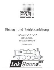
LokSound V3.5 ESU User Manual (325kb .pdf - Hornby
LokSound V3.5 ESU User Manual (325kb .pdf - Hornby
LokSound V3.5 ESU User Manual (325kb .pdf - Hornby

Create successful ePaper yourself
Turn your PDF publications into a flip-book with our unique Google optimized e-Paper software.
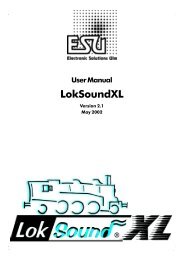
<strong>User</strong> <strong>Manual</strong><br />
<strong>LokSound</strong> V3.0 / <strong>V3.5</strong><br />
<strong>LokSound</strong>XL<br />
<strong>LokSound</strong> micro<br />
4 th edition, August 2005<br />
user manual <strong>LokSound</strong> / <strong>LokSound</strong>XL <strong>V3.5</strong>, 4th edition, 08/2005<br />
1
contens<br />
2<br />
Index<br />
1. Introduction .......................................................................................................................................... 3<br />
2. Characteristics of the <strong>LokSound</strong> decoders ........................................................................................... 4<br />
3. Installation of <strong>LokSound</strong> decoders ...................................................................................................... 5<br />
3.1. Connecting <strong>LokSound</strong> decoders in HO, TT, N, O gauge models ........................................................ 5<br />
3.1.1 Installation requirements ..................................................................................................................... 5<br />
3.1.2 Engines with DCC interface ................................................................................................................. 7<br />
3.1.3 Engines without interface .................................................................................................................... 7<br />
3.1.3.1 Connecting DC motors ......................................................................................................................... 8<br />
3.1.3.2 Connecting universal motors ............................................................................................................... 8<br />
3.1.4 Connecting the speaker ....................................................................................................................... 8<br />
3.1.5 Connecting auxiliary function devices ................................................................................................. 9<br />
3.1.6 Connecting a wheel sensor ................................................................................................................. 9<br />
3.2. Connecting the <strong>LokSound</strong>XL decoder .................................................................................................. 9<br />
3.2.1 General hints ........................................................................................................................................ 10<br />
3.2.2 Wiring diagram .................................................................................................................................... 10<br />
3.2.3.1 Connecting a DC- or coreless motor .................................................................................................... 11<br />
3.2.3.2 Connecting an alternating current (with field coils) motor ................................................................. 11<br />
3.2.4 Installing the speaker .......................................................................................................................... 11<br />
3.2.5.1 Auxiliary function outputs .................................................................................................................... 14<br />
3.2.5.2 Connecting headlights ......................................................................................................................... 14<br />
3.2.5.3 Connecting auxiliary functions ............................................................................................................. 14<br />
3.3.6.1 Connecting a wheel sensor ................................................................................................................. 14<br />
3.2.6.2 Connecting a reed contact with magnet .............................................................................................. 14<br />
3.2.6.3 Connecting a mechanical contact ....................................................................................................... 14<br />
3.2.6.4 Connecting a Hall sensor .................................................................................................................... 15<br />
3.2.7 Connecting additional reed contacts ................................................................................................... 15<br />
4. Set Up and installation of the decoder ................................................................................................ 15<br />
4.1 Analogue operation ............................................................................................................................. 16<br />
4.1.1 DC operation ........................................................................................................................................ 16<br />
4.2 Digital operation .................................................................................................................................. 16<br />
4.1.2 AC operation with conventional Märklin® controller ......................................................................... 16<br />
4.2.2 Using DCC .......................................................................................................................................... 16<br />
4.3 Resetting to factory pre-set values ....................................................................................................... 16<br />
5. Adjusting decoder parameters ............................................................................................................. 17<br />
5.1 CVs of <strong>LokSound</strong> decoders .................................................................................................................. 17<br />
5.2 Important settings of <strong>LokSound</strong> ........................................................................................................... 17<br />
5.2.1 Back EMF control (load control) ........................................................................................................... 18<br />
5.2.2 Speed Curve ......................................................................................................................................... 19<br />
5.2.3 Auxiliary function outputs .................................................................................................................... 19<br />
5.2.4 Sound adaptation ................................................................................................................................ 21<br />
5.2.5 Brake sections ...................................................................................................................................... 22<br />
5.2.6. Märklin® address ................................................................................................................................ 22<br />
5.2.7 Speed settings for DC operation ......................................................................................................... 23<br />
5.3 Adjusting CVs ....................................................................................................................................... 23<br />
5.3.1 Using the LokProgrammer ................................................................................................................... 23<br />
5.3.2 Using DCC systems .............................................................................................................................. 23<br />
5.3.3 Using Märklin® 6021 .......................................................................................................................... 23<br />
6. Frequently asked questions (FAQ) ...................................................................................................... 24<br />
7. List of all supported CVs ...................................................................................................................... 25<br />
9. Service-Support and assistance ............................................................................................................ 50<br />
<strong>User</strong> <strong>Manual</strong> <strong>LokSound</strong> / <strong>LokSound</strong>XL <strong>V3.5</strong>, 4th edition, 08/2005
1. Introduction<br />
Congratulations on purchasing a <strong>LokSound</strong> decoder.<br />
With <strong>LokSound</strong> your engines will sound like the<br />
prototype. You will soon notice that your <strong>LokSound</strong><br />
equipped engines are in the center of attention on any<br />
layout.<br />
Of course, you would like to install this decoder<br />
immediately, but first we kindly request you to read<br />
the following remarks:<br />
Please read this manual carefully before<br />
carrying out the installation!!! Although<br />
<strong>LokSound</strong> decoders are very robust, incorrect<br />
wiring may destroy the module!<br />
Due to its factory settings your new <strong>LokSound</strong> decoder<br />
can generally be used as is. In addition you may choose<br />
from a multitude of options that will help you adjust<br />
your <strong>LokSound</strong> decoder perfectly better to your<br />
model. Please familiarize yourself with the decoder<br />
before installing it and adjusting any parameters. Also<br />
note the recommendations regarding installation.<br />
Important warning:<br />
• <strong>LokSound</strong> decoders are designed for use in model<br />
trains only<br />
• Avoid mechanical force or pressure on the decoder<br />
• Do not expose to wet and humid conditions<br />
• Do not remove the heat shrink sleeve on the decoder<br />
• Never solder on the circuit board, extend cables if<br />
necessary<br />
• Never wrap the decoder in insulation tape, since<br />
this may cause overheating<br />
• Always disconnect the circuit when installing the<br />
decoder<br />
• Make sure that neither the <strong>LokSound</strong> decoder nor<br />
any blank wire ends may come into contact with<br />
the engine chassis (risk of short circuit). Cover any<br />
blank ends of unused wires.<br />
• Make sure that no wires are squeezed or cut by the<br />
model’s transmission parts when reassembling the<br />
engine<br />
Introduction<br />
user manual <strong>LokSound</strong> / <strong>LokSound</strong>XL <strong>V3.5</strong>, 4th edition, 08/2005<br />
Handle the speaker with extreme care: Do not<br />
touch the membrane or apply pressure! Solder<br />
speaker connections quickly and only at the<br />
intended contacts! Pay close attention to the<br />
instructions for installing the speaker!<br />
If you adhere to these warnings your <strong>LokSound</strong> decoder<br />
will reward you with trouble-free operation and long<br />
life.<br />
<strong>ESU</strong> electronic solutions ulm GmbH & Co. KG<br />
August 2005<br />
This manual has several Chapters explaining step by<br />
step how to proceed:<br />
Chapter 2 provides an overview of the characteristics<br />
of <strong>LokSound</strong> and <strong>LokSound</strong>XL decoders.<br />
Chapter 3 describes installation and connection. In<br />
Chapter 3.1 installation of <strong>LokSound</strong> decoders for HO,<br />
TT, N and O gauge are explained while Chapter 3.2<br />
deals with the <strong>LokSound</strong>XL for larger scale models (O,<br />
I, II,...).<br />
<strong>LokSound</strong> decoders are suitable for most digital<br />
command control systems. Chapter 4 provides an<br />
overview on which digital and analogue systems may<br />
be used to operate <strong>LokSound</strong> decoders as well as some<br />
particularities with certain systems.<br />
If you want to modify the preset running<br />
characteristics and/or sound effects we strongly<br />
recommend to read Chapter 5. Here you will gain an<br />
insight regarding the many options and how to adjust<br />
various parameters. You will also learn how to reset<br />
the decoder to the factory settings. The LokProgrammer<br />
(Art. No. 53451) makes setting any parameter of<br />
your <strong>LokSound</strong> decoder as easy as making a phone call<br />
or sending an email.<br />
Chapter 6 contains the answers to Frequently Asked<br />
Questions.<br />
In Chapter 7 a table provides all you need to know<br />
regarding the programming of decoder characteristics<br />
as outlined in Chapter 5.<br />
3
2. Characteristics of the <strong>LokSound</strong><br />
decoders<br />
The <strong>LokSound</strong> decoder is a universal electronic module<br />
for installation in model engines of most common<br />
scales. We recommend <strong>LokSound</strong> for all engines in<br />
TT, HO gauge as well as smaller engines in O gauge.<br />
<strong>LokSound</strong>XL is best suited for larger scales such as O,<br />
I, II and G gauge. <strong>ESU</strong> <strong>LokSound</strong> decoders revolutionize<br />
any model train layout. They intelligently combine a<br />
sophisticated digital decoder and a digital sound<br />
module. With <strong>LokSound</strong> you can run your engine with<br />
load control and many auxiliary functions while<br />
enjoying the original sound of the prototype. Its unique<br />
features provide flexibility and safety in operation<br />
that you have come to expect from a state of the art<br />
decoder. Even future standards are no problem for<br />
<strong>LokSound</strong>: its flash technology allows adaptation to<br />
the latest developments.<br />
Multi-protocol operation: <strong>LokSound</strong> decoders understand<br />
both, the commonly used Märklin® /<br />
Motorola® – format and the NMRA / DCC - system.<br />
Thus <strong>LokSound</strong> may be used with almost all currently<br />
available digital command control systems. Amongst<br />
others <strong>LokSound</strong> was tested with:<br />
• Digitrax® systems<br />
• Lenz Digital Plus®<br />
• ROCO® digital is cool®<br />
• Atlas® commander<br />
• Bachmann® E-Z command®<br />
• Märklin® 6021<br />
• Uhlenbrock® Intellibox (DCC+Motorola® System)<br />
• ZIMO MX-1 (DCC-Operation)<br />
• Fleischmann® Twin-Center<br />
• LGB® MTS® control<br />
Automatic change between all four operating modes<br />
during operation (AC , DC , DCC digital, Märklin®<br />
digital)<br />
Universal motor connection: All types of motors<br />
commonly used for model trains may be connected<br />
to <strong>LokSound</strong>:<br />
• DC motors (e.g. Bühler, Mabuchi, etc)<br />
• Coreless motors (e.g. Faulhaber, Maxxon, Hitachi)<br />
• Alternating current motors (AC motors)<br />
4<br />
Characteristics of the <strong>LokSound</strong> decoders<br />
High motor pulse frequency: The pulse frequency<br />
of 32 kHz (!) assures absolutely smooth running. Thus<br />
the motor runs silently and without any whine, heat<br />
generation is minimized and lifetime is prolonged.<br />
Even coreless motors may be operated with <strong>LokSound</strong><br />
decoders without any problem.<br />
Motor control: <strong>LokSound</strong> offers fourth generation<br />
load control. It may be adapted to suit each individual<br />
motor and can be switched off. Suitable for DC motors<br />
and coreless motors. Therefore your engine will always<br />
travel at the selected speed, no matter how large the<br />
load is or whether the engine is traveling up or down<br />
gradients.<br />
Dynamic Drive Control (DDC): back EMF active at<br />
low speeds for smooth slow running with reduced<br />
influence at high speeds.<br />
Back EMF for conventional operation: Back EMF<br />
is also active in conventional AC or DC mode. The<br />
user has full control of motor and acceleration.<br />
4 function outputs: In addition to the two lighting<br />
outputs, two more function outputs are available:<br />
switch on a smoke generator or the interior lighting<br />
or activate a digital coupler by pressing a button!<br />
Lighting effects and individually dimmable lamps help<br />
to make your models even more prototypical you<br />
will have lots of fun.<br />
Revolutionary function mapping: All functions can<br />
be allocated to any of 20 function buttons. Multiple<br />
allocations are possible allowing for the combination<br />
of sound and functions, e.g. the sound of shoveling<br />
coal and light flickering in the firebox. Also, we have<br />
integrated the latest NMRA DCC standards covering<br />
the use of F13 - F20<br />
Helper mode for consisting: With the Helper<br />
Function the user can select whether the engine runs<br />
standalone, head-of-consist, mid-of-consist or endof-consist.<br />
Consist mode CVs: influence the behavior of the<br />
function keys with the added CV 21 and 22.<br />
Brake sections: <strong>LokSound</strong> decoders recognize (and<br />
respond to) the most common brake systems: besides<br />
the Lenz brake generator, the Märklin® brake track<br />
is also supported.<br />
Circuit protection: the motor output and all function<br />
outputs are short circuit protected .<br />
<strong>User</strong> <strong>Manual</strong> <strong>LokSound</strong> / <strong>LokSound</strong>XL <strong>V3.5</strong>, 4th edition, 08/2005
Please make sure that the total current does<br />
not exceed the maximum permitted current<br />
for the function outputs and avoid short<br />
circuits between the outputs: <strong>LokSound</strong><br />
circuits are protected but an external voltage<br />
at the terminals of a function output may<br />
destroy the circuitry.<br />
conventional operation: <strong>LokSound</strong> decoders may<br />
be operated on AC- and DC layouts without any<br />
problems.<br />
Easy programming: Even with Märklin® 6021 all<br />
functions may be changed comfortably without<br />
opening the engine.<br />
A digital, four-tone sound module with unique<br />
characteristics:<br />
Prototype sounds: sounds of prototype engines were<br />
sampled using high fidelity microphones and recorded<br />
digitally on the flash memory module. Thus your<br />
engines sound exactly like the prototype!<br />
With four independent channels your engine sounds<br />
even more realistic , since you can simultaneously<br />
add 3 sound effects to the running sound. Pumps,<br />
power switches and squealing brakes can all be heard<br />
at the same time. The exhaust chuffs of steam engines<br />
vary with the revs of the drivers and the load. Now<br />
you can really hear your engine work. Diesel engines<br />
can now simulate the reduced revs of the diesel while<br />
the engine is coasting. The running sound and the sound<br />
of the fans (blowers) in electric engines is now<br />
separated. Additional sound effects can be activated<br />
by pressing a function button.<br />
Random sounds: sound effects such as air pump,<br />
water pump, shoveling coal, discharging compressed<br />
air, etc. are randomly triggered. Such sounds can be<br />
configured differently for stationary or moving<br />
engines.<br />
Individual volume control: You can individually<br />
control the volume for prime mover sounds, bell, horn<br />
and auxiliary sounds.<br />
Analog Sound: Even on conventional DC (or AC)<br />
layouts you will hear all prime mover sounds<br />
synchronized to the operation condition.<br />
user manual <strong>LokSound</strong> / <strong>LokSound</strong>XL <strong>V3.5</strong>, 4th edition, 08/2005<br />
Installation of <strong>LokSound</strong> decoders<br />
3. Installation of <strong>LokSound</strong> decoders<br />
3.1. Connecting <strong>LokSound</strong> decoders in N,<br />
TT, H0, 0 gauge models<br />
3.1.1 Installation requirements<br />
The engine must be in good mechanical condition:<br />
only an engine running smoothly in analogue mode<br />
should be modified for digital operation. An engine<br />
running poorly in analogue mode will not operate<br />
satisfactorily in digital mode – even with the best<br />
digital decoder. Check and clean or replace any wear<br />
and tear parts such as motor brushes, wheel contacts,<br />
lamps etc.<br />
Always remove the engine from the track when doing<br />
maintenance work or modifications. Make sure that<br />
no voltage is applied – intentionally or accidentally –<br />
while you work on the model.<br />
Pin Description Color Code<br />
1 motor terminal right orange<br />
2 rear light yellow<br />
3 function F1 green<br />
4 track connection left black<br />
5 motor terminal left gray<br />
6 headlight white<br />
7 common (+pole) blue<br />
8 track connection right red<br />
Pin Description Color Code<br />
1 motor terminal right orange<br />
2 motor terminal left gray<br />
3 track connection right red<br />
4 track connection left black<br />
5 head light white<br />
6 rear light yellow<br />
1<br />
6<br />
Figure1 Figure1: Figure1 NEM652 interface<br />
Figure1 Figure1: Figure1 NEM651 interface<br />
5
6<br />
violet<br />
AUX 2<br />
violet<br />
AUX 2<br />
green<br />
AUX 1<br />
blue<br />
green<br />
AUX 1<br />
chassis<br />
yellow white<br />
head<br />
light<br />
black red<br />
yellow white<br />
head<br />
light<br />
Engines with DCC interface<br />
rear<br />
light<br />
engine<br />
Figure Figure 2 22:<br />
2 Wiring of engines with DC motor and isulated functions<br />
rear<br />
light<br />
orange<br />
<strong>LokSound</strong><br />
<strong>LokSound</strong><br />
speaker100Ω<br />
2 x dark brown<br />
<strong>LokSound</strong><br />
black<br />
orange gray<br />
red<br />
engine<br />
Figure Figure 3a 3a: 3a 3a Wiring of engines with DC motors and functions with the common pole connected to the chassis<br />
black red<br />
engine<br />
yellow<br />
rear<br />
light<br />
head<br />
light<br />
white<br />
blue (optional)<br />
gray<br />
speaker 100Ω<br />
gray orange 2 x dark brown<br />
<strong>LokSound</strong><br />
<strong>LokSound</strong><br />
<strong>LokSound</strong> micro<br />
Figure Figure 3b 3b: 3b 3b Wiring <strong>LokSound</strong> micro (with blue common pole)<br />
speaker100Ω<br />
2 x dark brown<br />
<strong>User</strong> <strong>Manual</strong> <strong>LokSound</strong> / <strong>LokSound</strong>XL <strong>V3.5</strong>, 4th edition, 08/2005
<strong>LokSound</strong> decoders have a certain size: make sure,<br />
that the decoder fits easily into the engine, that no<br />
pressure is applied when replacing the housing onto<br />
the chassis and that no wires are squeezed between<br />
other parts. Further, make certain that moving parts<br />
such as transmissions and trucks are not obstructed<br />
by wires.<br />
Never pack a <strong>LokSound</strong> decoder in foam pads etc.<br />
The decoder heats up during operation; good heat<br />
dissipation is essential.<br />
Electronic components are sensitive to<br />
electrostatic charges: always make sure that<br />
your work place is grounded. If necessary, use<br />
an earthed wristband.<br />
When installing the decoder make sure that no metal<br />
part of the chassis touches any components of the<br />
decoder.<br />
3.1.2 Engines with DCC interface<br />
<strong>LokSound</strong> is supplied with an NMRA DCC 8-pin plug<br />
as shown in figure 1.Installation in engines with DCC<br />
socket is particularly easy:<br />
• Remove the body! Follow the instructions in the<br />
manual of the engine!<br />
• Remove the analogue plug or directional relay.<br />
Please keep the plug / relay for future use<br />
• Insert the decoder plug with pin 1 (the side with<br />
the red/orange wire) into the side of the socket<br />
that is usually marked with *, +, • or 1. Aviod<br />
bending any pins. Do not rely on the assumption<br />
that the wires have to lead in a certain direction,<br />
the marking is the only valid reference.<br />
• Place the decoder in a suitable location within the<br />
engine and fasten it with double sided tape or a<br />
drop of hot glue.<br />
• Now fix the speaker in a suitable place. See Chapter<br />
3.2.4<br />
user manual <strong>LokSound</strong> / <strong>LokSound</strong>XL <strong>V3.5</strong>, 4th edition, 08/2005<br />
Engines without interface<br />
3.1.3 Engines without interface<br />
Not every engine has a digital interface and thus the<br />
wiring becomes more elaborate: Disconnect any<br />
existing wires within the engine and any connection<br />
to the chassis. Both motor contacts must be insulated,<br />
make sure there isn’t any connection to the chassis,<br />
the wheels or the pantographs. This may easily be<br />
overlooked particularly in Fleischmann® models!<br />
After installing the decoder please check all<br />
connections with an Ohmmeter and watch<br />
for any short circuits between motor- and<br />
current pick-ups.<br />
How to proceed depends on how the headlights and<br />
other functions are wired in the engine:<br />
a) If headlights and functions are insulated from the<br />
engine chassis (free of any voltage) proceed as<br />
per figure 2.<br />
b) Headlights and functions may be connected with<br />
their common to the track voltage (e.g. almost<br />
all Märklin® -engines and older Fleischmann® or<br />
ROCO® engines) as per figure 3a<br />
Don’t get confused by the fact that both figure 2<br />
and 3a show how to wire DC - and coreless motors.<br />
How to wire a universal motor (Märklin®) is shown<br />
in figure 5.<br />
• Connect the red wire to the right rail pick-up (or<br />
center pick-up in AC models), the black wire to<br />
the left rail pick-up (common rails in AC models).<br />
• Connect the backup lights to the yellow wire, the<br />
headlights to the white wire.<br />
• Connect the green wire to the function output<br />
AUX-1. Allocate the function button later.<br />
• Connect the purple wire to the function output<br />
AUX-2. Allocate the function button later.<br />
• Connect the speaker to the two dark-brown wires.<br />
• If the headlights and functions are insulated from<br />
the chassis (see figure 3a) connect all commons<br />
to the blue wire. Make sure the blue wire has no<br />
contact to the engine chassis.<br />
7
3.1.3.1 Connecting DC motors<br />
Connecting DC motors<br />
3.1.3.2 Connecting universal motors<br />
• Connect the orange wire with the motor termi- Figure 5 shows how a universal motor (e.g. AC motor<br />
nal, that was originally wired to the right wheel by Märklin®) is connected to a <strong>LokSound</strong> decoder:<br />
pick-up (center pick-up in AC models).<br />
• Connect the orange wire with the motor terminal<br />
• The gray wire goes to the terminal, that was that was originally connected with the center<br />
originally connected to the left wheel pick-up pick-up.<br />
(common rails for AC models).<br />
• Connect the gray wire to the motor terminal that<br />
• Exchanging the wires changes direction of travel. was originally connected to the common / wheel<br />
• Some engines with the Märklin® 5-pole high pick-up.<br />
performance drive may have 3 RFI suppressors • Exchanging the wires will change direction of<br />
soldered to the motor shield.<br />
travel.<br />
• The two suppressors that connect the motor • Solder an inductor (choke) with at least 3.9 mH to<br />
terminals with the motor chassis must be each motor terminal. They are available as spare<br />
removed (see figure 4).<br />
parts from Märklin® under article number 516520.<br />
remove capacitor<br />
• The RFI suppression inductor remains attached to<br />
the collector terminal of the motor and has to be<br />
soldered to the blue wire.<br />
8<br />
orange<br />
grey<br />
Figure Figure 4 44:<br />
4 5-pole Märklin® high performance drive<br />
alternating<br />
current motor<br />
orange<br />
blue<br />
grey<br />
inductor<br />
3,9 µH<br />
<strong>LokSound</strong><br />
Figure Figure 5: 5: Wiring to Märklin® universal motor<br />
Please note: If a universal motor is connected<br />
<strong>LokSound</strong> will automatically deactivate Back<br />
EMF Control. The principle of Back EMF<br />
Control does not work with universal motors.<br />
3.1.4 Connecting the speaker<br />
speaker<br />
chamber<br />
solder here!<br />
<strong>LokSound</strong> decoders may only be used with the<br />
speakers supplied by <strong>ESU</strong> GmbH & Co. KG . They<br />
have an impedance of 100 Ohm. The use of speakers<br />
from others manufactures may cause considerable<br />
distortion and in extreme cases, may even destroy<br />
the <strong>LokSound</strong> decoder.<br />
The correct position of the speaker is crucial to<br />
achieve high quality sound. A speaker that is installed<br />
without a sound chamber will not generate good<br />
sound. Therefore carefully select the location and<br />
sound chamber for the speaker.<br />
The speaker must be installed in such a way that the<br />
sound waves are not unduly blocked.<br />
<strong>User</strong> <strong>Manual</strong> <strong>LokSound</strong> / <strong>LokSound</strong>XL <strong>V3.5</strong>, 4th edition, 08/2005
Please handle speakers with extreme care:<br />
don’t apply pressure or touch the membrane!<br />
The speaker’s magnets are very powerful! Keep<br />
all metal items away and secure the speaker<br />
firmly when soldering. The soldering iron may<br />
pull the speaker due the magnetic field and<br />
destroy it.<br />
Connect the speaker to the 2 dark brown wires of the<br />
<strong>LokSound</strong> module. Make sure that you use a small<br />
soldering iron (max. 20W) and only heat the marked<br />
spots as shown in the figure (close to the edge of the<br />
small contact plate). Polarity is not important. An<br />
optimal sound effect is achieved by putting the<br />
speaker into a sound chamber, which is supplied with<br />
the speaker. This will increase the sound pressure and<br />
channel the sound in one direction. Without sound<br />
chamber the sound effect may be unsatisfactory.<br />
Feed the speaker wires through a small hole in the<br />
sound chamber.<br />
3.1.5 Connecting auxiliary function<br />
devices<br />
Any load may be connected to the lighting and auxiliary<br />
function outputs as long as it doesn’t exceed the<br />
maximum current (see technical data in the appendix<br />
of this manual). Note that the overload protection<br />
of the decoder reacts quickly and will switch off all<br />
functions immediately in case of an overload or<br />
short circuit.<br />
Therefore use only 16 V lamps (or a higher<br />
voltage) and a maximum nominal current of<br />
50mA: incandescent lamps have a high starting<br />
current and may trigger the overload<br />
protection during switch-on.<br />
Use only digital smoke generators (e.g. Seuthe No.<br />
11) for engines whose lighting and auxiliary function<br />
outputs are connected as shown in figure 2. Other<br />
smoke generators draw too much current. There are<br />
smoke generators with more than 250mA nominal<br />
current on the market!<br />
Engines that are wired as shown in figure 3 need an<br />
analogue smoke generator e.g. Seuthe No. 10.<br />
Connecting auxiliary function devices<br />
user manual <strong>LokSound</strong> / <strong>LokSound</strong>XL <strong>V3.5</strong>, 4th edition, 08/2005<br />
Make sure that the total current for the<br />
function outputs does not exceed the<br />
permitted current rating and avoid short<br />
circuits between outputs. Although the output<br />
circuits are protected, a high voltage on the<br />
terminals or a short circuit may cause<br />
damage.<br />
3.1.6 Connecting a wheel sensor<br />
reed contact<br />
drive wheel<br />
miniature<br />
magnet<br />
Figure Figure 6 66:<br />
6 Connecting a wheel sensor<br />
To synchronize the exhaust chuffs with the revs of<br />
the drivers an external sensor can be (but does not<br />
have to be) used. The sensor input is described in<br />
figure 6. The <strong>LokSound</strong> micro does not support this<br />
sensor input.<br />
<strong>LokSound</strong> decoders support reed contacts or<br />
mechanical contacts.<br />
If a reed contact is to be used, a miniature magnet<br />
(available at hobby shops) must be attached to the<br />
driving wheel axle in such a way that the magnet<br />
releases the reed contact once every turn. Miniature<br />
reed contacts have been proven to be very reliable.<br />
They are available at special electronics stores.<br />
Suitable magnets may be bought at model train shops.<br />
(e.g. Mini-track magnets) which might have to be<br />
shaped to fit.<br />
All double pole (mechanical) contacts that are<br />
insulated (not connected to the chassis) are suitable.<br />
Before the wheel sensor will work various CVs have<br />
to be programmed. See Chapter 5.2.4 on page 21.<br />
9
Connecting the <strong>LokSound</strong>XL decoder<br />
3.2. Connecting the <strong>LokSound</strong>XL decoder 3.2.1 General hints<br />
The <strong>LokSound</strong>XL decoder is partly supplied as an open When modifying an engine for digital operation<br />
circuit board. Do not remove the shrink sleeve, as please take note of the following:<br />
there will be no warranty. Like any electronic device Make sure that no motor terminal is connected to<br />
handling the <strong>LokSound</strong>XL requires some care: the wheel pick-ups or pantographs; otherwise the<br />
decoder may be destroyed. Separate all connections<br />
Please make absolutely certain that the including possible electrical contact via the engine<br />
module does not have contact with any metal chassis.<br />
parts: risk of short circuits!<br />
The <strong>LokSound</strong>XL has a suresize and requires adequate<br />
space. Take care, that the decoder fits easily into the<br />
engine, that no pressure is applied when replacing<br />
the housing onto the chassis and that no wires are<br />
squeezed between other parts. Further, make certain<br />
that moving parts such as transmissions and trucks<br />
are not obstructed by wires.<br />
Fix the decoder with double sided adhesive tape, some<br />
hot glue or screws, but never pack it into foam pads,<br />
etc. The decoder heats up during operation and good<br />
heat dissipation is essential.<br />
After installation, please check all connections with<br />
an Ohmmeter and search for possible short circuits,<br />
particularly between the motor terminals and the<br />
wheel pick-ups.<br />
The <strong>LokSound</strong>XL has a few more terminals required<br />
for the sound effects. <strong>LokSound</strong>XL is supplied with<br />
screw terminals for easy wiring without soldering.<br />
Please note the following:<br />
• <strong>LokSound</strong>XL decoders have two screw<br />
terminalstrips (No. 1 + No. 2):<br />
• Please make sure, that you always use the correct<br />
terminal!<br />
• Make certain, that the cable size is large enough<br />
for the terminals (min 0.20mm2)<br />
• Tinn the ends of the wires or use cable glands<br />
• Take care to avoid short circuits while inserting<br />
the wires into the terminals.<br />
• Use a suitable screw driver. Hold down the screw<br />
terminals while tightening the screws to avoid<br />
any mechanical force on the circuit board.<br />
• Provide adequate RFI suppression of the motor: a<br />
100 nF capacitor parallel to the motor terminals<br />
is the absolute minimum.<br />
10<br />
Please note, that RFI suppression may be<br />
achieved by different means. We recommend<br />
to leave the chokes supplied with the engine<br />
in the circuit.<br />
• However, all RFI suppression capacitors that<br />
connect the motor terminals with the (motor)<br />
chassis must be removed (see figure 4).<br />
3.2.2 Wiring diagram<br />
Figures 8 and 9 show the general wiring layout for<br />
<strong>LokSound</strong>XL decoders: The left terminal strip (No. 1)<br />
contains all connections required for running and<br />
sound. The right terminal strip (No. 2) is solely for<br />
auxiliary function outputs.<br />
alternating<br />
current<br />
motor<br />
rail<br />
right<br />
left<br />
inductor<br />
speaker<br />
1-1<br />
1-2<br />
1-3<br />
1-4<br />
1-5<br />
1-6<br />
1-7<br />
1-8<br />
1-9<br />
Figure Figure 7: 7: Wiring to Märklin® universal motor<br />
<strong>User</strong> <strong>Manual</strong> <strong>LokSound</strong> / <strong>LokSound</strong>XL <strong>V3.5</strong>, 4th edition, 08/2005
Connecting a DC- or coreless motor<br />
3.2.4 Installing the speaker<br />
Please make sure you do not confuse the<br />
terminals. Wrong wiring may cause damage You may only use the specially adapted speakers (1<br />
or destruction of the decoder – despite the Watt, 32 Ohm) provided by <strong>ESU</strong> GmbH & Co. KG for<br />
protective circuitry!<br />
<strong>LokSound</strong>XL decoders.<br />
Connect the right wheel pick-up to terminal 1-1 and<br />
the left one to terminal 1-2. Terminals 1-3, 1-4 and<br />
1-6 are reserved for the motor. For DC and coreless<br />
motors only terminals 1-3 and 1-6 are used. Details are<br />
described in Chapter 3.2.3.1 and 3.2.3.2<br />
A wheel sensor can be wired to terminals 1-4 and 1-<br />
5. Details are explained in Chapter 3.2.6.1<br />
The speaker is to be connected to terminals 1-8 and<br />
1-9. Installation of the speaker is explained in Chapter<br />
3.2.4. Terminal strip 2 serves for the wiring of<br />
headlights and auxiliary functions only.<br />
Please note that the common of all outputs is<br />
terminal 2-9 (positive voltage). Details are<br />
explained in Chapter 3.2.5.2 and 3.2.5.3.<br />
3.2.3.1 Connecting a DC- or coreless<br />
motor<br />
According to the general wiring diagram on page 12.<br />
Please note, that any suppression chokes should<br />
remain in the motor leads. The parameters for load<br />
control vary depending on the type of motor (Bühler,<br />
Mabuchi, Faulhaber) and have to be adjusted<br />
accordingly. Also refer to Chapter 5.2.1<br />
When wiring the motor, please note that terminals<br />
1-3 and 1-6 are used (the ones in between remain<br />
disconnected)!<br />
3.2.3.2 Connecting an alternating<br />
current (with field coils) motor<br />
To simplify the modification of older I gauge models<br />
with universal motors (with field coils) the motor<br />
can be wired straight to the <strong>LokSound</strong>XL decoder:<br />
The field coil is wired to the terminals 1-3 and 1-6.<br />
Swapping the terminals results in change of direction.<br />
The suppressor choke remains with one contact on<br />
the motor terminal. The other lead is wired to terminal<br />
1-4 of the decoder. As soon as a universal motor<br />
is connected to <strong>LokSound</strong>XL, load control is<br />
automatically switched off. Universal motors are<br />
not suitable for load control.<br />
user manual <strong>LokSound</strong> / <strong>LokSound</strong>XL <strong>V3.5</strong>, 4th edition, 08/2005<br />
speaker<br />
chamber<br />
solder here!<br />
Other speakers will distort the sound and may cause<br />
damage or destruction of the decoder.<br />
We can not recommend the use of speakers designed<br />
for HO decoders either.<br />
The appropriate location within the model is crucial<br />
for excellent sound reproduction. A speaker without<br />
the sound chamber will never generate excellent<br />
sound. Therefore carefully select the space for the<br />
speaker and the sound chamber within the model.The<br />
speaker must be installed in such a way that the<br />
sound waves are not unduly blocked.<br />
Please handle speakers with extreme care:<br />
don’t apply pressure or touch the membrane!<br />
The speaker’s magnets are very powerful! Keep<br />
all metal items away and secure the speaker<br />
firmly when soldering.<br />
Connect the speaker to the terminals 1-8 and 1-9 of<br />
the <strong>LokSound</strong>XL module. Make sure that you use a<br />
small soldering iron (max. 20W) and only heat the<br />
marked spots as shown in the figure (close to the<br />
edge of the small contact plate). Polarity is not<br />
important. Make sure no solder drips on the<br />
membrane.<br />
An optimal sound effect is achieved by putting the<br />
speaker in a sound chamber, which is supplied with<br />
the speaker. This will increase the sound pressure and<br />
channel the direction of sound. Without sound<br />
chamber the sound effect may be unsatisfactory.<br />
Feed the speaker wires through a small hole into the<br />
sound chamber.<br />
11
Figure Figure 8: 8: Connecting the <strong>LokSound</strong>XL decoder<br />
12<br />
rail<br />
right<br />
2-1<br />
1-1<br />
left<br />
2-2<br />
1-2<br />
2-3<br />
1-3<br />
2-4<br />
DC Motor<br />
Connecting the <strong>LokSound</strong>XL decoder<br />
1-4<br />
2-5<br />
1-5<br />
2-6<br />
1-6<br />
2-7<br />
1-7<br />
2-8<br />
1-8<br />
2-9<br />
1-9<br />
Figure Figure 8a: 8a: Setting for 8 - 16 Ohm<br />
Figure Figure 8b: 8b: Setting for 16 - 32 Ohm<br />
<strong>User</strong> <strong>Manual</strong> <strong>LokSound</strong> / <strong>LokSound</strong>XL <strong>V3.5</strong>, 4th edition, 08/2005
Rear lights<br />
head lights<br />
2-1<br />
1-1<br />
2-2<br />
1-2<br />
AUX1<br />
2-3<br />
AUX2<br />
AUX3<br />
1-3<br />
Figure Figure 9: 9: Connecting the <strong>LokSound</strong>XL decoder<br />
Connecting the <strong>LokSound</strong>XL decoder<br />
2-4<br />
1-4<br />
2-5<br />
1-5<br />
AUX4<br />
2-6<br />
1-6<br />
user manual <strong>LokSound</strong> / <strong>LokSound</strong>XL <strong>V3.5</strong>, 4th edition, 08/2005<br />
AUX5 / Reed-In1<br />
AUX6 - Reed-In2<br />
2-7<br />
1-7<br />
2-8<br />
1-8<br />
2-9<br />
1-9<br />
common (V+)<br />
13
Auxiliary function outputs<br />
3.2.5.1 Auxiliary function outputs<br />
short intervals. The lamps have to be replaced by<br />
others that are suitable for 19 Volts.<br />
<strong>LokSound</strong>XL has 8 (!) function outputs, two of which<br />
are reserved for headlights. The remaining 6 (AUX 1<br />
through AUX 6) can be used for lighting, smoke<br />
generators, couplers, etc.<br />
However, before you can use these outputs, you have<br />
to activate them as described in Chapter 5.2.3.<br />
The brightness of the outputs can be adjusted<br />
individually in 15 steps for each output. Each function<br />
output can also be programmed to provide certain<br />
lighting effects (blinking, etc.).<br />
After you have checked above points you may switch<br />
on the power.<br />
We strongly recommend to carry out this initial<br />
check on a track section with overload protection.<br />
Programming tracks of modern digital systems offer<br />
this protection. Our LokProgrammer (part Number<br />
53451) also offers extremely reliable overload<br />
protection.<br />
The pre-set engine address is 03.<br />
Does the engine travel in both directions?<br />
Turn the lights on: are they operating correctly? If<br />
the <strong>LokSound</strong> decoder was built into an engine with<br />
NMRA / DCC interface: check if the plug has been<br />
inserted correctly.<br />
3.2.5.2 Connecting headlights<br />
Headlights and back-up lights are to be wired to terminal<br />
block 2 as per figure 3.<br />
Generally, the outputs will have the full track voltage<br />
(between 14 and 25 Volts, depending on the power<br />
supply). Therefore you should equip your engine with<br />
lamps suitable for that voltage. In older models the<br />
lamps may be connected to the chassis (e.g. Märklin).<br />
In this case you may not wire the return from the<br />
lamp to the terminal 2-9. Thus the lamp works against<br />
the common return (chassis).<br />
In many models LEDs or 1.5 Volt lamps are used.<br />
They can also be operated with <strong>LokSound</strong>XL decoders,<br />
but not without some preparation: use a 1k Ohm / 0.5<br />
Watt resistor in series with each LED or 1.5 Volt<br />
lamp. You also have to reduce the output voltage to<br />
1.5 V by setting the appropriate CV as per Chapter<br />
5.2.3.<br />
When using 1.5 Volt lamps it is not sufficient to reduce<br />
the brightness (dimming level) via the CV. Due to the<br />
PWM-mechanism the full voltage will be applied for<br />
14<br />
3.2.5.3 Connecting auxiliary functions<br />
The function outputs AUX 1 to AUX 6 can be used for<br />
many different purposes, such as switching a smoke<br />
generator, interior lights, automatic change of<br />
headlights according to the rules of the Swiss Railways<br />
(SBB), etc. Please note, that the outputs are intended<br />
for resistive loads such as lamps, smoke generators,<br />
relays, etc. the direct connection of a motor is not<br />
recommended due to its inductive peaks. Use a relay<br />
to switch the motor.<br />
3.3.6.1 Connecting a wheel sensor<br />
To synchronize the exhaust chuffs with the revs of<br />
the drivers an external sensor can be used. The sensor<br />
input is available on terminal 1-7.<br />
The <strong>LokSound</strong>XL decoder supports reed contacts,<br />
mechanical contacts or Hall sensors. Many models<br />
(e.g. Bachmann or Märklin®) are supplied complete<br />
with mechanical contacts.<br />
3.2.6.2 Connecting a reed contact with<br />
magnet<br />
If a reed contact is to be used one miniature magnet<br />
(available at hobby shops) for each exhaust chuff<br />
must be attached to the driving wheel axle in such a<br />
way that the magnet triggers the reed contact once<br />
every turn.<br />
Miniature reed contacts have been proven to be very<br />
reliable. They are available at special electronics<br />
stores. Suitable magnets may be purchased at model<br />
train shops. (e.g. mini-track magnets).<br />
3.2.6.3 Connecting a mechanical contact<br />
Many models are supplied complete with a<br />
mechanical contact. It has to be connected in the<br />
same way as a reed contact, namely to terminals 1-<br />
4 and 1-7.<br />
All double pole (mechanical) contacts that are<br />
insulated from the chassis may be used.<br />
<strong>User</strong> <strong>Manual</strong> <strong>LokSound</strong> / <strong>LokSound</strong>XL <strong>V3.5</strong>, 4th edition, 08/2005
eed switch(SRK)<br />
drive wheel<br />
1-1<br />
1-2<br />
1-3<br />
1-4<br />
1-5<br />
1-6<br />
1-7<br />
1-8<br />
1-9<br />
Figure Figure 10a: 10a: Connecting a reed switchwith magnet<br />
drive wheel<br />
miniature magnet<br />
Vs<br />
GND<br />
Output<br />
TLE4905<br />
1-1<br />
1-2<br />
1-3<br />
1-4<br />
1-5<br />
1-6<br />
1-7<br />
1-8<br />
1-9<br />
Figure Figure 10b: 10b: Connecting a Hall sensor<br />
3.2.6.4 Connecting a Hall sensor<br />
A Hall sensor is an electronic circuit that responds to<br />
an alternating magnetic field similar to a reed 4.2.1<br />
Using Märklin® 6021.<br />
<strong>LokSound</strong> decoders may be used with all Märklin®<br />
control devices or compatible systems. The functions<br />
F1 to F4, however, can only be activated with the<br />
„new Motorola® format“. To activate this format<br />
put DIP switch 2 of the 6021 to the upper („On“)<br />
position. Hall sensors are easier to adjust since the<br />
distance between sensor and magnet is not critical.<br />
A commonly used hall sensor, that can be purchased<br />
via mail order is the TLE4905 by Siemens / Infineon.<br />
The terminal Vs of the TLE4905 has to be wired to<br />
terminal 1-4, GND to terminal 1-5 and the Pin Output<br />
to terminal 1-7.<br />
Connecting a Hall sensor<br />
user manual <strong>LokSound</strong> / <strong>LokSound</strong>XL <strong>V3.5</strong>, 4th edition, 08/2005<br />
2-1<br />
2-2<br />
2-3<br />
2-4<br />
2-5<br />
2-6<br />
2-7<br />
2-8<br />
2-9<br />
reed<br />
switch(SRK)<br />
resistor 10k<br />
0,25W<br />
Figure10c: Figure10c: Connecting external Reed switch<br />
3.2.7 Connecting additional reed switch<br />
<strong>LokSound</strong>XL decoders have two additional inputs<br />
that can trigger various functions. The main purpose<br />
of these inputs is to trigger sounds by means of track<br />
magnets. A reed switch has to be wired to one of<br />
these inputs and a magnet is to be placed at the<br />
appropriate location on the layout. Every time the<br />
engines passes that spot a sound effect will be<br />
triggered.<br />
With the aid of these sensors users of the LGB MZS<br />
with Lokmaus can also trigger the many sound<br />
effects of the <strong>LokSound</strong>XL decoder.<br />
The inputs REED-IN1 and REED-IN2 share the terminals<br />
2-7 and 2-8 with the auxiliary function outputs AUX<br />
5 and AUX 6. Therefore AUX 5 and AUX 6 are not<br />
available if you use these inputs.<br />
4. Set Up and installation of the decoder<br />
After successful installation you may now operate<br />
the decoder.<br />
The following will outline how you can check if you<br />
have installed the decoder correctly. Chapter 4.1<br />
describes analogue operation. In Chapter 4.2 you will<br />
learn how to operate <strong>LokSound</strong> with various digital<br />
systems.<br />
Before changing any decoder settings (e.g. engine<br />
address, sound volume) we recommend to read<br />
Chapter 5. There you will learn which parameters<br />
are available and how they may be adjusted with the<br />
most common DCC command stations.<br />
15
Analogue operation<br />
After installation you may test the <strong>LokSound</strong> decoder 4.2 Digital operation<br />
as follows:<br />
please check all connections carefully using an Ohmmeter:<br />
- are there any short circuits between the<br />
4.1.2 AC operation with conventional<br />
Märklin® controller<br />
motor terminals and the wheel pick-ups?<br />
Operation with conventional Märklin® controllers<br />
Are all connections between motor terminals and works as you know it from other models. Speed is<br />
the chassis isolated?<br />
controlled by turning the knob.<br />
Are lamps connected properly and isolated from the To change direction the knob has to be turned to the<br />
chassis?<br />
Is the decoder installed safely to avoid contact with<br />
left beyond the stop position.<br />
the chassis?<br />
Please note: The engine must have completely<br />
Is there sufficient space around the <strong>LokSound</strong> decoder stopped before changing direction. Never<br />
to allow for heat dissipation?<br />
Could the <strong>LokSound</strong> decoder or any of the wires be<br />
change direction while the engine is moving!<br />
squeezed when refitting the housing?<br />
Is the speaker installed in such a way that sound can<br />
emit from the engine without obstruction?<br />
4.2.2 Using DCC<br />
<strong>LokSound</strong> may be operated with any DCC compatible<br />
system. When using Lenz digital plus version 3.0 the<br />
4.1 Analogue operation<br />
auto detect function does not work with 14 speed<br />
steps. Set 28/128 speed steps at all times. The auto-<br />
4.1.1 DC operation<br />
detect function is activated every time the decoder<br />
receives power (when turning on power to the layout)<br />
Sound on<br />
Sound on<br />
or when you switch on the headlights. During this<br />
process the headlights have to be switched on and<br />
Motor on<br />
Motor on<br />
you have to turn the control knob (or slide control)<br />
until the lights burn steadily. Should you change the<br />
speed step setting during operation you have to<br />
interrupt power to the decoder for a short time in<br />
order to reactivate the auto detect function.<br />
Figure Figure 10d<br />
10d<br />
Operation using a conventional DC controller is<br />
possible without any problems exept for one<br />
limitation. The engine will only start moving when<br />
the track voltage reaches 7–8 Volts. Maximum speed<br />
will be reached when turning the controller to the<br />
limit. This is absolutely normal and is due to the<br />
minimum voltage the <strong>LokSound</strong> decoder requires for<br />
operation. Running sounds are available in this<br />
operating mode but not additional sound effects.<br />
16<br />
4.3 Resetting to factory pre-set values<br />
You may rest the decoder settings to the factory<br />
pre-set values at any time. Write value 08 in CV 08.<br />
A reset of the sound files is only possible with the aid<br />
of the LokProgrammer 53451.<br />
<strong>User</strong> <strong>Manual</strong> <strong>LokSound</strong> / <strong>LokSound</strong>XL <strong>V3.5</strong>, 4th edition, 08/2005
Adjusting decoder parameters<br />
5. Adjusting decoder parameters<br />
Please note that not all CVs have factory pre-set<br />
values:<br />
Chapter 5 provides information on how to change<br />
the settings of <strong>LokSound</strong> decoders. Please take your Some CV values vary depending on the type of sound<br />
time to read and understand the somewhat complex effect. While most CVs require numerical values,<br />
explanations. After the introduction into the world others represent storage locations that manage<br />
of decoder parameters (called CVs) in Chapter 5.1, various functions simultaneously (mostly switching<br />
you will find in Chapter 5.2 all you need to know on or off). CVs 29 and 49 are good examples: for<br />
about the effects different CVs have on the properties these CVs the value has to be calculated individually,<br />
of <strong>LokSound</strong> decoders.<br />
depending on the parameters you want to adjust:<br />
Chapter 5.3 explains how CVs may be set with various<br />
DCC command stations as well as the Märklin®<br />
command stations. You will find a complete list of all<br />
CVs in Chapter 7.1.<br />
5.1 CVs of <strong>LokSound</strong> decoders<br />
<strong>LokSound</strong> decoders are compatible with the NRMA /<br />
DCC standard. This means that all parameters<br />
controlling the properties of <strong>LokSound</strong> decoders are<br />
stored in so called CVs (Configuration Variables).<br />
<strong>LokSound</strong> decoders support 230 variables. This large<br />
number of CVs indicates the multitude of possibilities<br />
available with <strong>LokSound</strong> decoders.<br />
In order to get the best out of your decoder and to<br />
easily manage this large number of settings, we<br />
recommend the use of our LokProgrammer, part no.<br />
53451.<br />
With the help of the LokProgrammer all CVs may be<br />
programmed easily and comfortably on your PC.<br />
Please note that CVs that are not programmed<br />
properly could impede the performance of the<br />
decoder. The LokProgrammer part no. 50450 is not<br />
suitable for programming this decoder.<br />
All CVs may be programmed without the LokProgrammer<br />
by using any DCC system that is NMRA /<br />
DCC compatible or with Märklin® 6021.<br />
Chapter 5.3 explains, how it works.<br />
In each CV, values from 0 to 255 may be stored.<br />
The properties of the decoder vary depending on the<br />
stored value. When you check the list of CVs in<br />
Chapter 7.1 you will notice that most CVs have<br />
numerical values.<br />
For example CV 1 contains the engine address. This<br />
number may vary between 1 and 127 (see range of<br />
values).<br />
The factory setting is 3.<br />
user manual <strong>LokSound</strong> / <strong>LokSound</strong>XL <strong>V3.5</strong>, 4th edition, 08/2005<br />
First you decide which options should to be<br />
turned on or off. In the column „value“ you<br />
will find two numbers for each option. The<br />
value 0 indicates that the option is switched<br />
off, otherwise the value may range from 1 to<br />
128. Add all values of the individual options to<br />
get the total value to be written into the CV.<br />
Example Example 1: 1: Let’s assume you want to use the<br />
Intellibox DCC with 128 speed steps and analogue<br />
detection should be active (because you want to<br />
control some locos in analogue mode). All other<br />
options are turned off. CV 29 shows the value 6 (0 +<br />
2 + 4 + 0 = 6).<br />
Example Example 2: 2: You want to turn the volume of the<br />
decoder down. Set CV 63 to a value between 1 and<br />
64, let’s say 25.<br />
5.2 Important settings of <strong>LokSound</strong><br />
Details of the most important CVs may be found in<br />
Chapter 5.2. Please study these instructions carefully<br />
before you do any program changes.<br />
Careful deliberation will help you to find the optimal<br />
settings to achieve the desired effects with your<br />
<strong>LokSound</strong> decoder.<br />
17
Back EMF control (load control)<br />
5.2.1 Back EMF control (load control) case you have to reduce the value for CV 56, in the<br />
first case increase the value. The internal PI regulation<br />
<strong>LokSound</strong> decoders utilize fourth generation load<br />
of <strong>LokSound</strong> can be adjusted with CV 54 and CV 55.<br />
Control assuring constant speed regardless of the<br />
Depending on the type of motor the parameters may<br />
actual load when using DC motors. Load control was<br />
have to be adjusted to achieve optimal running<br />
optimized and tested with motors from:<br />
performance.<br />
• ROCO®,<br />
<strong>LokSound</strong> decoders are factory pre-set for the use<br />
• Bachmann (Liliput),<br />
with ROCO®-, Brawa®- or Kato motors.<br />
• BRAWA®,<br />
Parameter „K“, stored in CV 54, influences how<br />
• Märklin®,<br />
strongly load control will effect the driving<br />
performance. The higher the value, the more load<br />
• LGB,<br />
control will respond to any changes. Adjust this value<br />
• Bühler,<br />
with care, because too high values could lead to<br />
• Mabuchi.<br />
irregular and „hard“ driving performance. If you<br />
Load control may be deactivated (if desired). prefer smooth running, try to reduce the value step<br />
by step until you reach an optimum.<br />
Please note that load control is always turned off<br />
when using AC motors – no matter what settings<br />
Parameter „I“, stored in CV 55 provides important<br />
are used.<br />
information to the <strong>LokSound</strong> decoder regarding the<br />
motor type used: certain electric motors respond<br />
differently to adjustments of the rpm’s. The longer a<br />
AC motors are not suitable for load control motor takes to respond, the lower the value in CV 55.<br />
However, it is not easy to recognize the degree of<br />
inertia. In general: the more poles a motor has and<br />
the bigger it is, the more fly wheels it has, the slower<br />
it is and the lower the value should be set in CV 55.<br />
For optimal programming proceed as follows:<br />
Read out the value in CV 53 as described above. Leave<br />
the value of CV 55 (parameter I .I.) for the time being<br />
and test the engine. Now change the value of CV 54<br />
in steps of 5 downwards or upwards and monitor the<br />
running properties of the engine. If there is no<br />
improvement leave the value of CV 54 and change<br />
the value of CV 55 (intensity of control) in steps of 5<br />
until an optimum is reached.<br />
How to switch on load control<br />
Set the first bit of CV 49. Read out the CV: load<br />
control is deactivated if the value is 0 or 2. To activate<br />
it, just add 1 to the actual value and enter. Example:<br />
CV 49 reads 2. To activate load control set CV 49 to 3.<br />
You will find a detailed description of all possible<br />
values for CV 49 in Chapter 7.1.<br />
Parameters of Back EMF control<br />
The internally used PI-control algorithm of Back EMF<br />
control depends on 3 parameters: the control<br />
reference voltage is stored in CV 53, the control<br />
parameters are in CVs 54 and 55.<br />
Reference voltage:<br />
In CV 53 you set the voltage that should come back<br />
from the motor.<br />
This value depends on the track voltage and the<br />
coefficient of utilization of the motor. A coefficient<br />
of 75 % and a track voltage of 16 Volts adds up to<br />
a voltage of 16 V * 75 % = 12 Volts. This value has<br />
to be written into CV 56. The voltage (here: 12 V)<br />
may be entered in 0.25V-increments. This results in<br />
a value of 30 (12 V * 2.5) for CV 53. If you don’t know<br />
the exact motor coefficient, you may obtain the<br />
value experimentally as follows:<br />
Check if the engine really reaches top speed at the<br />
highest speed step or if you cannot detect any speed<br />
changes at the maximum speed step. In the latter<br />
18<br />
Please note, that incorrectly set parameters<br />
may impede the effect of Back EMF control<br />
to the point that the motor may stop<br />
altogether. Refer to our website http://<br />
www.loksound.de for suggested values for<br />
commonly used motor / drive combinations<br />
such as:<br />
Parameters for Fleischmann® motors<br />
Engines with the traditional Fleischmann® motor<br />
should be programmed as follows:<br />
CV 54 = about 14 – 18<br />
CV 55 = 20<br />
<strong>User</strong> <strong>Manual</strong> <strong>LokSound</strong> / <strong>LokSound</strong>XL <strong>V3.5</strong>, 4th edition, 08/2005
Speed Curve<br />
Parameters for Märklin® high performance You may also define an individual speed curve:<br />
motor<br />
The 5-pole high performance motor from Märklin®<br />
(series 37xxx) is well suited for the <strong>LokSound</strong> decoder<br />
when programmed as follows:<br />
Store the speed curve values in CVs 67 to 94 (as per<br />
figure 12). Those 28 values will determine the 256<br />
speed steps. This method permits optimizing the<br />
running performance. This mode is also activated<br />
CV 54 = about 20 – 25<br />
via CV 29. We recommend the use of the <strong>ESU</strong> Lok-<br />
CV 55 = 38<br />
Programmer and its software for easy calculation<br />
and programming.<br />
5.2.2 Speed Curve<br />
<strong>LokSound</strong> decoders recognize 256 internal speed<br />
steps. They may be adapted to the characteristics of<br />
each engine and assigned to the available speed steps<br />
(14, 28 or 128). NMRA allows two choices:<br />
Speed curve via CV 2, 5 and 6 (figure 11).<br />
0 128<br />
256<br />
VMid<br />
VHigh<br />
VStart<br />
0 14<br />
Figure Figure 11 11: 11 Speed curve with CV2, 6, 5<br />
Set the starting voltage in CV 2 and the maximum<br />
speed with CV 5. CV 6 represents the medium speed.<br />
You may define the shape of the curve (straight or<br />
with two different gradients). This mode is activated<br />
via CV 29 (see Chapter 7.1).<br />
0 128 256<br />
0 14 28<br />
Figure Figure 12 12 12: 12 Speed curve with CV 67 - 90<br />
user manual <strong>LokSound</strong> / <strong>LokSound</strong>XL <strong>V3.5</strong>, 4th edition, 08/2005<br />
5.2.3 Auxiliary function outputs<br />
<strong>LokSound</strong> decoders have 4 physical function outputs,<br />
two for directional lighting, two for auxiliary loads.<br />
Additinal 10 functions may be activated by pressing<br />
a button to trigger various sound effects.<br />
If you do not want to use the physical function outputs<br />
AUX 1 and AUX 2 you may control two additinal sound<br />
effects (12 in total).<br />
In addition the functions „sound on / off“ and<br />
„acceleration on / off“ are available. The latter turns<br />
off the acceleration- and deceleration rate and is<br />
often used for precise control of the engines<br />
particularly while shunting. In „shunting mode“ the<br />
speed is halved.<br />
Assignment of function buttons<br />
The outputs may be assigned to the available function<br />
buttons. Each function button is linked to a CV in<br />
which any number of events may be combined. Page<br />
26-27 shows the different possible combinations and<br />
also the ex-factory setting.<br />
Please note:<br />
• Some functions are directional.<br />
• Your DCC command station may not have all<br />
necessary function buttons.<br />
• Each of the function outputs must be turned on or<br />
off separately.<br />
The value that has to be entered into each individual<br />
control-CV is calculated as follows:<br />
Switching on function outputs<br />
Each of the function outputs can / must be turned on,<br />
before it can be used. You may program any of eight<br />
available lighting effects for each output:<br />
19
• Dimmer: normal, continuous power to load<br />
• Blinking light: the output blinks with an adjustable<br />
frequency<br />
• Inverse blinking light: the output blinks as usual<br />
but in opposite sequence. This permits to activate<br />
alternately blinking lights.<br />
• Strobe<br />
• Double Strobe<br />
• Random, fire box<br />
• Smoke, for controlling the intensity of the smoke<br />
generator<br />
• Zoom<br />
• Mars light<br />
• Gyra light<br />
There is a CV (CV 113 - 120) for each output, in which<br />
the desired mode may be stored. Please note that<br />
you may deactivate each output by assigning „0“ if<br />
it is not needed. CVs 117 – 120 are only available on<br />
<strong>LokSound</strong>XL.<br />
The lighting outputs are factory pre-set to „on“. In<br />
steam engines this is also true for the AUX 1 output<br />
that is assigned to the headlight button.<br />
Dimming of lamps<br />
With <strong>LokSound</strong> you may dim the lamps in 15 steps to<br />
adapt the brightness optimally to your model. The<br />
lamps are pulsed, i.e.: they are continuously switched<br />
on and off. The brightness of each output may be<br />
adjusted separately. The desired dimming value (0 to<br />
15) has to be added to the value of the corresponding<br />
control-CV (113 - 120) that defines the function mode.<br />
Blinking frequency and duration of „bright<br />
period“<br />
If a function output has been set to „blinking“ or<br />
„inverse blinking“, the duration of the „bright period“<br />
(defines blinking frequency) and the on / off ratio<br />
have to be taken from CV 112 (see Chapter 7.1).<br />
The „bright period“ is adjustable in 33 steps. It is<br />
always a multiple of 65.5 milliseconds. The On / Off<br />
ratio is adjustable in 16 steps from 1/16 to 16/16. A<br />
ratio of 8/16 indicates that the light output remains<br />
„on“ for the same period as it is „off“. The value to<br />
be entered into the control-CV 113 is calculated as<br />
follows:<br />
Duration of „On“ period (value: 0 – 15) *<br />
16 + On / Off ratio<br />
20<br />
Speed Curve<br />
Examples<br />
• Example 1: smoke generator on AUX 1 and F5.<br />
Let’s assume you want to control a smoke generator<br />
with function button F5 that should be connected to<br />
output AUX 1. Please refer to the installation<br />
instructions in Chapter 2.5. The output AUX 1 must<br />
be activated and assigned to the F5 button:<br />
First we activate the output. In this example we want<br />
to use the dimming function (the output must be<br />
active continuously) and set at 100% brightness. CV<br />
115 controls output AUX 1 (see paragraph 7.1).The<br />
value to be entered in CV 115 is 15 for maximum<br />
brightness.<br />
Now we have to assign function button F5 to output<br />
AUX 1: refer to figure 13: control-CV 171 controls<br />
the F5 button (third column). In CV 171 we enter<br />
those functions that should be switched with the F5<br />
button. We look at the table in figure 13, locate the<br />
intersection of the row for F5 and column AUX 1 and<br />
find the number (in this case 4). Once we enter this<br />
value in CV 171 the F5 button controls the output<br />
AUX 1. In order to also switch AUX 1 with F5 when<br />
reversing the same value has to be entered in CV<br />
174.<br />
• Example 2: blinking light on AUX 2 and F6<br />
We want to connect a „blinking light“ to AUX and<br />
control it via the F6 function button. We also want<br />
the brightness to be set to 6/15 of the maximum<br />
value. The „bright period“ and the „On / Off“ ratio<br />
are set as described in paragraph 5.2.3.3.<br />
First we have to activate output AUX 2 and set it to<br />
„blinking“. We achieve this by entering 16 (for<br />
blinking) + 5 (= 6/15 of maximum brightness) = 21in<br />
CV 116.<br />
Next we assign output AUX 2 to the F6 button. We<br />
enter the functions to be controlled via F6 into control-<br />
CV 177. Again we consult the table in figure 13, find<br />
the intersection between row F6 (forward) and<br />
column AUX 2 and enter the number (in this case 8)<br />
from the table in CV 177. Now the F6 „forward“<br />
button controls the output AUX 2. To program the<br />
same for reversing enter value 8 in CV 183.<br />
• Example 3: Deceleration on / off with F5<br />
Here we want to activate / deactivate the<br />
acceleration / deceleration with F5. This function<br />
represents a „logical“ function and not a „physical“<br />
output and thus does not have to be configured. We<br />
<strong>User</strong> <strong>Manual</strong> <strong>LokSound</strong> / <strong>LokSound</strong>XL <strong>V3.5</strong>, 4th edition, 08/2005
only have to assign the function „deactivate<br />
deceleration“ to the F5 key by entering value 1 in CV<br />
172 (see figure 13). If the same effect should work<br />
while reversing enter 1 in CV 175. We recommend<br />
a PC and LokProgrammer for programming function<br />
outputs:<br />
<strong>LokSound</strong> decoders offer so many possible<br />
combinations that it is recommended to use the<br />
LokProgrammer (part no. 53451) in conjunction with<br />
a personal computer.<br />
5.2.4 Sound adaptation<br />
<strong>LokSound</strong> decoders offer many possibilities to adjust<br />
sound effects. All parameters are stored in CVs that,<br />
like all others, may be modified. Adaptation of<br />
revolutions for diesel and pitch for steam exhaust<br />
chuffs. The revolutions of a diesel motor may be<br />
modified with 2 CVs:<br />
Enter the revolutions of the idling diesel motor in CV<br />
59. The standard value of 32 permits reproduction of<br />
the sound at original speed, while value 16 reduces<br />
this to half speed.<br />
Enter the revolutions at maximum speed<br />
(respectively maximum revs) in CV 60:<br />
Value 255 means double the original speed. Use the<br />
same parameters when adapting the pitch of the<br />
exhaust chuffs for steam engines:<br />
The interval of the exhaust chuffs should be shorter<br />
and vary in pitch with increasing speed.<br />
Specific settings for steam engines<br />
To simulate a steam engine you have to synchronize<br />
the exhaust chuffs with the revolutions of the drivers.<br />
There are two ways to achieve this:<br />
• • With an external wheel sensor<br />
• Speed step dependent<br />
Depending on the method selected, certain CVs have<br />
to be set accordingly. <strong>LokSound</strong> is factory pre-set to<br />
speed step dependent adjustment.<br />
Using a wheel sensor<br />
The wheel sensor must be connected as described in<br />
Chapter 3.1.6 and 3.2.6. Then two more parameters<br />
have to be adjusted:<br />
Set CV 57 to value 0 and enter a value > =1 in CV 58.<br />
CV 58 defines after how many pulses by the sensor<br />
the next exhaust chuff will be reproduced. Normally<br />
one exhaust chuff per pulse should be played.<br />
Sound adaptation<br />
user manual <strong>LokSound</strong> / <strong>LokSound</strong>XL <strong>V3.5</strong>, 4th edition, 08/2005<br />
Speed step dependent method<br />
With this method the interval between exhaust<br />
chuffs is set with CV 57 and CV 58. This method is<br />
recommended if an external wheel sensor cannot be<br />
used.<br />
The adaptation of this variable to the wheel / gearbox<br />
combination may require some experiments. It pays<br />
to spend some time in order to achieve an optimal<br />
result. This feature works best with Back EMF control.<br />
With Märklin® engines with universal motor (Back<br />
EMF is always switched off) only a compromise can<br />
be reached. I<br />
• Set CV 57 to 10 and CV 58 to 110.<br />
• Put the engine onto the track and drive it with<br />
speed step 1 (sound is switched on).<br />
• • Measure the time in seconds it takes the driver to<br />
complete one turn at this speed.<br />
• Divide the time by 0.064.<br />
• Enter a rounded value without decimal points in<br />
CV 57, e.g. 0.9 seconds / 0.064 = 14-5= Value 9.<br />
• Increase the speed and check whether the exhaust<br />
chuffs match the turns of the drivers.<br />
If the exhaust chuffs are too fast, increase the<br />
value in CV 58 gradually, if they are too slow,<br />
decrease the value in CV 58.<br />
n this case we recommend the use of an external<br />
wheel sensor. For CV adaptation proceed as follows:<br />
Adjusting the volume by CV<br />
The volume of <strong>LokSound</strong> decoders may be adapted<br />
gradually. For the master volume, enter the desired<br />
value in CV 63. Permitted values are: 0 (quiet) to 64<br />
(loud).<br />
However, for controlling the volume of the horn, there<br />
exists CV 121. You can enter the desired volume level<br />
here.<br />
For the volume of the bell, CV122 is responsible and<br />
with CV123, you can control the volume of the other<br />
auxiliary sounds.<br />
21
Mute / Adjusting volume by function key<br />
The <strong>LokSound</strong> <strong>V3.5</strong> decoders offers a mute function.<br />
You can enable the mute by pressing the F8 button.<br />
For <strong>LokSound</strong> <strong>V3.5</strong>, you can also easily adjust the<br />
volume during normal operation by the F8 function<br />
button: Press the F8 button two times quickly in series.<br />
Each time you do this, the volume is increased by one<br />
step up to the max. After you have reached the<br />
maximum volume, the volume is reset to the lowest<br />
value again. You can toggle through 4 different<br />
volume levels.<br />
Random sound effects<br />
CV 61 and CV 62 define the frequency of random<br />
sounds that are played while a steam engine is<br />
stationary. CV 61 contains the minimal time between<br />
2 random sounds, CV 62 the maximum. Both represent<br />
an interval in which <strong>LokSound</strong> randomly selects and<br />
plays sounds. The unit of both CVs is 1.0 second.<br />
Example: the minimum interval in CV 61 should be<br />
8 seconds. Enter 8 into CV 61. The maximum interval<br />
in CV 62 should be 30 seconds. Enter 30 in CV 62.<br />
Doppler effect<br />
<strong>LokSound</strong> <strong>V3.5</strong> offers a Doppler effect. While blowing<br />
the horn by pressing the F2 button, release the F2<br />
button for a very short time and press the button<br />
again. This will enable the doppler mode: The horn<br />
continues to blow, but - depending on the actual<br />
speed- the pitch of the horn- and prime mover sounds<br />
are lowered.<br />
You can end the Doppler by releasing the horn button.<br />
After some 5 seconds, the horn and diesel engine will<br />
returnto their normal operation.<br />
5.2.5 Brake sections<br />
<strong>LokSound</strong> decoders respond to the most commonly<br />
used brake generators on the market:<br />
• Lenz-brake generator in DCC operation<br />
• Märklin® brake track<br />
As soon as the <strong>LokSound</strong> decoder recognizes a brake<br />
command it brakes with the deceleration set in CV<br />
4. After this forced stop (once the signal aspect has<br />
changed) the engine begins to move again and<br />
22<br />
Brake sections<br />
accelerates according to the value set in CV 3. In<br />
order to support this function some CVs have to be<br />
programmed. This feature is activated in CV 51.<br />
Lenz brake generator<br />
The Lenz brake generator LG 100 uses the<br />
mechanisms recommended by the NMRA standards<br />
and is supported by <strong>LokSound</strong> decoders. Write value<br />
8 in CV 51.<br />
Märklin® brake track<br />
Instead of digital signals the Märklin® brake track<br />
supplies a DC voltage to the tracks. To activate this<br />
you must write 1 in CV 51. Do not activate the<br />
Märklin® brake track and the analogue DC operation<br />
at the same time, because the DC supplied by the<br />
Märklin® brake track could be interpreted as<br />
analogue DC. With CV 50 you can switch off the<br />
analogue mode (see paragraph 7.1).<br />
5.2.6. Märklin® address<br />
In order to be able to use functions F5 to F9 with the<br />
Märklin® 6021 command station <strong>LokSound</strong> decoders<br />
have a second Märklin® address. It is always the<br />
following number to the actual address. Set bit 3 in<br />
CV 49.<br />
5.2.7 Speed settings for DC operation<br />
You can individually adjust the starting voltage and<br />
the maximum speed for the conventional DC<br />
operation. CV 125 is responsible for starting voltage.<br />
The higher the value is, the more voltage is applied<br />
to the motor when started. For the maximum speed<br />
in DC mode, you can reduce it by lowering the value<br />
stored in CV 126.<br />
<strong>User</strong> <strong>Manual</strong> <strong>LokSound</strong> / <strong>LokSound</strong>XL <strong>V3.5</strong>, 4th edition, 08/2005
5.3 Adjusting CVs<br />
Speed settings for DC operation<br />
The Lenz command station displays „err02“, the<br />
After having been introduced to the effects controlled<br />
by CVs in Chapters 5.1 and 5.2 we now need to clarify<br />
how to set the CVs. In principle there are 3<br />
possibilities:<br />
• With a PC and LokProgrammer (article no. 53451)<br />
• With a DCC compatible digital command station<br />
(e.g. Intellibox, Lenz digital plus)<br />
Arnold command station „short circuit“:<br />
This is caused by the very sensitive overload<br />
protection of the digital system. The <strong>LokSound</strong><br />
decoder with the built in audio amplifier uses a higher<br />
current than other decoders and thus triggers the<br />
overload protection. To rectify this, solder a 47 Ohm<br />
(0.5 Watt) resistor in one of the two wires connecting<br />
the digital command station with the programming<br />
• • With Märklin® 6021<br />
Depending on the system used the procedure varies<br />
track. See figure 13.<br />
.<br />
5.3.3 Using Märklin® 6021<br />
5.3.1 Using the LokProgrammer<br />
With the Märklin® command station you cannot<br />
The LokProgrammer by <strong>ESU</strong> <strong>ESU</strong> GmbH GmbH & & Co. Co. KG KG KGoffers<br />
the easiest method to adjust CVs of <strong>LokSound</strong><br />
decoders:<br />
It is done with a mouse click using your MS-Windows®<br />
computer. The LokProgrammer eliminates<br />
searching for various CV numbers and values. With<br />
modify standard CVs as it does not comply with the<br />
NMRA DCC standards. However, the most important<br />
CVs of <strong>LokSound</strong> decoders may be changed with a<br />
specific programming mode.<br />
Please note: this applies only to CVs from 1 to 79, and<br />
only for values from 1 to 79.<br />
the LokProgrammer you can modify the sounds of<br />
<strong>LokSound</strong> decoders and you may also create your<br />
own sound effects.<br />
Programming mode for 6021:<br />
Set the drive control knob to 0. Remove any other<br />
engines from the track. Observe the blinking signals<br />
The LokProgrammer (order no. 53451) is available at of the engine! Press the „stop“- and „go“ button of<br />
model train outlets complete with detailed operating the 6021 simultaneously until a reset has been<br />
instructions.<br />
triggered. Alternately you can remove the power<br />
The LokProgrammer part no. 50450 is not suitable<br />
for programming <strong>LokSound</strong> decoders version 3.5.<br />
plug for a moment. Press the „stop“ button in order<br />
to switch off the track voltage. Enter the current<br />
decoder address (alternately: 80).<br />
5.3.2 Using DCC systems<br />
There is no „one fits all“ instruction for programming<br />
CVs with various DCC systems. There are too many<br />
differences between the popular DCC systems.<br />
Whenever possible you should use the DCC direct<br />
mode or DCC paged mode.<br />
Lenz digital plus<br />
There are various software versions available of the<br />
Lenz digital plus command station. You need<br />
firmware version 2.3 or 3.0 in order to program<br />
<strong>LokSound</strong> decoders. Contact Lenz for more details<br />
regarding upgrades of older versions.<br />
Use „paged CV“ mode for programming. Depending<br />
on the firmware version the „CV mode“ might cause<br />
problems.<br />
Older command stations such as „Digital plus“, „Lenz<br />
compact“ and „Arnold Digital“ create another<br />
phenomenon:<br />
Programming is not possible.<br />
user manual <strong>LokSound</strong> / <strong>LokSound</strong>XL <strong>V3.5</strong>, 4th edition, 08/2005<br />
• Confirm by activating change of direction (turning<br />
the control knob beyond the stop position towards<br />
the left) and hold the knob, then press the „go“<br />
button.<br />
• The <strong>LokSound</strong> decoder is now in programming<br />
mode (headlights are blinking). Now enter the<br />
number of the parameter (CV) you want to change<br />
(two digit number).<br />
• Confirm by activating change of direction (double<br />
blinking headlights).<br />
• Now enter the new value for the CV (2 digits).<br />
• Confirm by activating change of direction<br />
(headlights light up for about 1 second, then<br />
continue blinking).<br />
• Now you can continue with other CVs in the same<br />
manner.<br />
23
Brake sections<br />
• To exit the programming mode select CV 80 or 6. Frequently asked questions (FAQ)<br />
switch off the track voltage for a moment (press<br />
Usually there is no fault in the <strong>LokSound</strong> decoder if<br />
„stop“ button followed by „go“ button on 6021).<br />
it does not work as desired but very likely some CVs<br />
Please note that 6021 only permits entries from<br />
are set incorrectly. Here are some examples of what<br />
01 to 80. There is no value „0“, instead always<br />
may happen and how to solve the problem:<br />
enter 80.<br />
• • Headlights and sound work, write CVs as well, but<br />
the engine does not move.<br />
A short circuit on the motor terminals or a high<br />
program track<br />
current draw may trigger the overload protection.<br />
Perhaps the motor is not fully insulated against<br />
resistor 47W<br />
the chassis. To eliminate this as the cause of the<br />
malfunction, remove the motor and test-run it<br />
while outside the engine.<br />
central unit<br />
If load control is deactivated the starting voltage<br />
Figure Figure 13: 13:<br />
13:<br />
may be too low (CV 2).<br />
Lenz command station with 47 Ohm resistor • The engine jerks and runs very uneven at low speed<br />
with activated load control.<br />
Deactivate load control and check if the problem<br />
remains (refer to Chapter 5.2.1). If the problem<br />
disappears then the parameters for load control<br />
have to be adjusted (as per 5.2.1).<br />
• • • The engine runs perfectly, but there is no sound.<br />
Check the wires to the speaker.<br />
With the Märklin® 6021 the new Motorola format<br />
has to be used, otherwise the F1 button does not<br />
work (refer to Chapter 4.2.1). If the format is set<br />
correctly, the speaker may be damaged.<br />
• • The engine runs perfectly, but the headlights do<br />
not work or switch on and off depending on the<br />
speed step.<br />
If you have an engine with DCC socket, check if<br />
the plug has been inserted in the correct position<br />
(refer to Chapter 3.2).<br />
• • If you operate <strong>LokSound</strong> in DCC mode please<br />
refer to Chapter 4.2.2 where the solution to this<br />
problem is described.<br />
• • I would like to reset the <strong>LokSound</strong> decoder to the<br />
factory settings. What do I have to do?<br />
With the aid of a PC and the LokProgrammer<br />
software a reset is easily achieved. If you only<br />
want to reset the CVs write value 8 in CV 8.<br />
• • • I have read the instruction carefully but still have<br />
problems. What can I do?<br />
24<br />
<strong>User</strong> <strong>Manual</strong> <strong>LokSound</strong> / <strong>LokSound</strong>XL <strong>V3.5</strong>, 4th edition, 08/2005
If you have further questions regarding<br />
<strong>LokSound</strong> decoders please contact our<br />
Technical Customer Service.<br />
Contact details are listed in Chapter 8 on page<br />
50 of this <strong>Manual</strong>.<br />
Should you have come to the conclusion you do not<br />
want to install decoders yourself we can offer you<br />
another solution:<br />
<strong>ESU</strong> electronic solutions ulm GmbH & Co. KG offers<br />
an installation service in conjunction with experienced<br />
specialists.<br />
Ask your dealer for the new <strong>ESU</strong> service pack: We<br />
arrange for installation of your decoder: comfortable<br />
and without risk for you!<br />
7. List of all supported CVs<br />
The following pages provide a list of all CVs of<br />
<strong>LokSound</strong> decoders. Please refer to the remarks<br />
regarding the concept of CVs in Chapter 5.1.<br />
Change CVs only if you have a clear<br />
understanding of the implications. Incorrect<br />
settings may lead to malfunctioning decoders.<br />
Frequently asked questions<br />
user manual <strong>LokSound</strong> / <strong>LokSound</strong>XL <strong>V3.5</strong>, 4th edition, 08/2005<br />
25
Function Button<br />
26<br />
Description<br />
Control CV A<br />
Function Mapping<br />
Headlight<br />
value 1 2 4 8 16 32 64 128<br />
stand forward 129<br />
stand backward 132<br />
drive forward 135<br />
drive backward 138<br />
F0 light forward 141 1 4<br />
F0 light backward 144 2 4<br />
F1 key F1 forward 147<br />
F1 key F1 backward 150<br />
F2 key F2 forward 153<br />
F2 key F2 backward 156<br />
F3 key F3 forward 159<br />
F3 key F3 backward 162<br />
F4 key F4 forward 165<br />
F4 key F4 backward 168<br />
F5 key F5 forward 171<br />
F5 key F5 backward 174<br />
F6 key F6 forward 177<br />
F6 key F6 backward 180<br />
F7 key F7 forward 183<br />
F7 key F7 backward 186<br />
F8 key F8 forward 189<br />
F8 key F8 backward 192<br />
F9 key F9 forward 195<br />
F9 key F9 backward 198<br />
F10 key F10 forward 201<br />
F10 key F10 backward 204<br />
F11 key F11 forward 207<br />
F11 key F11 backward 210<br />
F12 key F12 forward 213<br />
F12 key F12 backward 216<br />
F13 key F13 forward 219<br />
F13 Key 13 backward 222<br />
F14 Key 14 forward 225<br />
F14 key 14 backward 228<br />
F15 Key 15 forward 231<br />
F15 Key 15 backward 234<br />
sensor 1 forward 237<br />
sensor 1 backward 240<br />
sensor 2 forward 243<br />
sensor 2 backward 246<br />
Back-Up Lights<br />
AUX 1<br />
AUX 2<br />
<strong>User</strong> <strong>Manual</strong> <strong>LokSound</strong> / <strong>LokSound</strong>XL <strong>V3.5</strong>, 4th edition, 08/2005<br />
AUX 3 only <strong>LokSound</strong>XL<br />
AUX 4 olny <strong>LokSound</strong>XL<br />
AUX 5 only <strong>LokSound</strong>XL<br />
AUX 6 only<strong>LokSound</strong>XL
Control CV B<br />
Acceleration On / Off<br />
Shunting mode On / Off<br />
Sound On / Off<br />
user manual <strong>LokSound</strong> / <strong>LokSound</strong>XL <strong>V3.5</strong>, 4th edition, 08/2005<br />
Shift Mode<br />
Blower<br />
Function Mapping<br />
value 1 2 4 8 16 32 64 128 value 0, 1-16<br />
130 131<br />
133 134<br />
136 137<br />
139 140<br />
142 143<br />
145 146<br />
148 4 149<br />
151 4 152<br />
154 32 155 1<br />
157 32 158 1<br />
160 161 2<br />
163 164 2<br />
166 167 3<br />
169 170 3<br />
172 173 4<br />
175 176 4<br />
178 1 2 179 0<br />
181 1 2 182 0<br />
184 185 5<br />
187 188 5<br />
190 64 191 6<br />
193 64 194 6<br />
196 197<br />
199 200<br />
202 203<br />
205 206<br />
208 209<br />
211 212<br />
214 215<br />
217 218<br />
220 221<br />
223 224<br />
226 227<br />
229 230<br />
231 232<br />
235 236<br />
238 239<br />
241 242<br />
244 245<br />
247 248<br />
Doppler ON Sound Slot 1<br />
Mute / Volume Control<br />
Dynamic brake<br />
Ccontrol CV<br />
Sound Slot 1-16<br />
27
1 Engine address Address of engine 1-127 3<br />
2 Start voltage Sets the minimum speed of the engine 1-75 3<br />
3 Acceleration This value multiplied by 0.869 is the time from stop to<br />
maximum speed<br />
0-64 8<br />
4 Deceleration This value multiplied by 0.869 is the time from maximum<br />
speed to stop<br />
0-64 6<br />
5 Maximum speed Maximum speed of engine 0-64 64<br />
6 Medium speed Medium speed of engine 0-64 22<br />
7 Version number Internal software version of <strong>LokSound</strong> decoder<br />
8 Manufacturer’s ID Manufacturer’s ID - <strong>ESU</strong> –<br />
Writing value 8 in this CV triggers a reset to factory values<br />
151<br />
13 Analogue mode F1-F8 Status of functions F1 to F8 in analogue mode 0-255 0<br />
Bit Description value<br />
0 function F1 1<br />
1 function F2 2<br />
2 function F3 4<br />
3 function F4 8<br />
4 function F5 16<br />
5 function F6 32<br />
6 function F7 64<br />
7 function F8 128<br />
14 Analogue mode FL, Status of functions FL, F9 to F12 in analogue mode 0-255 3<br />
F9-F12 Bit Description value<br />
0 function FL (f) 1<br />
1 function FL (r) 2<br />
2 function F9 (f) 4<br />
3 function F10 (f) 8<br />
4 function F11 16<br />
5 function F12 32<br />
6 function F9 (r) 64<br />
7 function F10 (r) 128<br />
17 Extended engine address long address of engine 128 192<br />
18 CV17 contains byte with higher value<br />
(bit 6 and 9999, bit 6 and bit 7 must always be active),<br />
CV18 contains byte with lower value. Only<br />
9999<br />
active when function is switched on in CV 29 (see below).<br />
19 Consist address Additional address for consist<br />
value 0 or 128 means: consist address deactivated<br />
1-127 consist address, normal direction<br />
129-255 consist address, reverse direction<br />
0-255 0<br />
28<br />
List of all supported CVs<br />
CV Name Description Range Default<br />
<strong>User</strong> <strong>Manual</strong> <strong>LokSound</strong> / <strong>LokSound</strong>XL <strong>V3.5</strong>, 4th edition, 08/2005
List of all supported CVs<br />
CV Name Description Range Default<br />
21 Consist mode F1-F8 Status of functions F1 to F8 in consist mode 0-255 0<br />
Bit Description value<br />
0 function F1 1<br />
1 function F2 2<br />
2 function F3 4<br />
3 function F4 8<br />
4 function F5 16<br />
5 function F6 32<br />
6 function F7 64<br />
7 function F8 128<br />
22 Consist mode FL, Status of functions FL, F9 to F12 in consist mode 0-255 0<br />
F9-F12 Bit Description value<br />
0 function FL (f) 1<br />
1 function FL (r) 2<br />
2 function F9 (f) 4<br />
3 function F10 (f) 8<br />
4 function F11 16<br />
5 function F12 32<br />
6 function F9 (r) 64<br />
7 function F10 (r) 128<br />
29 Configuration register The most complex CV within the DCC standards.<br />
This register contains important information,<br />
which is only relevant in DCC mode.<br />
4<br />
Bit function value<br />
0 Reverse direction of travel<br />
(forward becomes reverse)<br />
normal direction 0<br />
reversed direction 1<br />
1 speed steps (only for DCC mode)<br />
14 speed steps 0<br />
28 or 128 speed steps 2<br />
2 analogue operation<br />
analogue operation off 0<br />
analogue operation on 4<br />
4 selection of speed curve<br />
speed curve through CV 2,5, 6 0<br />
speed curve through CV 67 – 96 16<br />
5 selection of engine address<br />
(only for DCC operation)<br />
short addresses (CV 1) in DCC mode 0<br />
long addresses (CV 17 + 18) in DCC mode 32<br />
user manual <strong>LokSound</strong> / <strong>LokSound</strong>XL <strong>V3.5</strong>, 4th edition, 08/2005<br />
29
CV Name Description Range Default<br />
49 Extended configuration Activate support for brake sections<br />
or switch off Back EMF control<br />
0-255 19<br />
Bit description value<br />
0 load control off 0<br />
load control activated 1<br />
1 DC motor PWM frequency<br />
15 kHz pulse frequency 0<br />
30 kHz pulse frequency 2<br />
2 Märklin® delta mode<br />
Delta mode off<br />
Delta mode on<br />
0<br />
4<br />
3 Märklin® second address<br />
second address off 0<br />
second address on 8<br />
4 Automatic speed step detection<br />
DCC speed step detection off 0<br />
DCC speed step detection on 16<br />
5 LGB function button mode<br />
LGB mode off 0<br />
LGB mode on 32<br />
6 Zimo manual function<br />
Zimo manual function off 0<br />
Zimo manual function on 64<br />
7 Function key toggle mode<br />
Sound triggered by off2on only<br />
Sound triggered by off2on and on2off<br />
0<br />
128<br />
50 Analogue mode Selection of desired analogue mode 0-3 3<br />
bit description value<br />
0 AC analogue mode<br />
AC analogue mode off 0<br />
AC analogue mode on 1<br />
1 DC analogue mode<br />
DC analogue mode off<br />
DC analogue mode on<br />
0<br />
2<br />
51 Brake mode Selection of desired brake mode 3<br />
Bit description value<br />
0 Märklin® brake mode<br />
Märklin® brake mode off 0<br />
Märklin® brake mode on 1<br />
1 Zimo brake mode<br />
Zimo brake mode off<br />
Zimo brake mode on<br />
0<br />
2<br />
2 not used<br />
3 Lenz DC brake mode<br />
Lenz brake mode off 0<br />
Lenz brake mode on 8<br />
30<br />
List of all supported CVs<br />
<strong>User</strong> <strong>Manual</strong> <strong>LokSound</strong> / <strong>LokSound</strong>XL <strong>V3.5</strong>, 4th edition, 08/2005
List of all supported CVs<br />
CV Name Description Range Default<br />
52 Helper mode Select the helper mode setting whilst consist mode<br />
is active<br />
0<br />
description value<br />
Helper mode off, use CV 21, 22 only 0<br />
locomotive is head-of-consist 1<br />
locomotive is mid-of-consist 2<br />
locomotive is end-of-consist 4<br />
locomotive is standalone 8<br />
53 Control reference Defines the Back EMF voltage, which the<br />
motor should generate at maximum speed.<br />
The higher the efficiency of the motor, the<br />
higher this value may be set. If the engine<br />
does not reach maximum speed, reduce<br />
this parameter.<br />
0-80 56<br />
54 Load control K-component of internal PI-controller 0-80 32<br />
parameter K Defines the effect of load control. The<br />
higher the value, the stronger the effect<br />
of Back EMF control<br />
55 Load control „I“-component of internal PI-controller 0-80 24<br />
parameter I Defines momentum (inertia) of motor.<br />
The higher the momentum of the motor<br />
(large flywheel or bigger diameter motor)<br />
the lower this value has to be set (see<br />
Chapter 5.2.1)<br />
56 Operating range of 0 – 100% 0-64 64<br />
load control Defines up to which speed in % load control<br />
will be active. A value of 32 indicates that<br />
load control will be effective up to half speed.<br />
57 Sound mode 1 Multiplied by 0,64 is the time in seconds 0-127<br />
between two chuff sounds at speed step 1.<br />
Value 0 indicates that period between<br />
<strong>LokSound</strong> <strong>LokSound</strong> <strong>LokSound</strong> Steam: 20<br />
Diesel: 0<br />
exhaust chuffs is controlled by a wheel sensor <strong>LokSound</strong>XL <strong>LokSound</strong>XL Steam: 50<br />
Diesel: 0<br />
58 Sound mode 2 Value defines the gradual decrease of 0-127<br />
intervals of exhaust chuffs with increasing <strong>LokSound</strong> <strong>LokSound</strong> Steam: 115<br />
speed. A higher value indicates a more rapid<br />
decrease, a lower value a slower decrease.<br />
Diesel: 0<br />
Electric:: 0<br />
If exhaust chuffs are triggered by a wheel<br />
sensor (if CV 57 = 0), this value specifies the<br />
number of trigger pulses required for one<br />
exhaust chuff.<br />
<strong>LokSound</strong>XL <strong>LokSound</strong>XL Steam: 95<br />
59 Sound Divided by 32 this will yield the factor for<br />
reproducing the sound at the slowest speed<br />
step. Values < 32 are slower, values > 32 are<br />
faster than original speed.<br />
0-64 32<br />
60 Sound Divided by 32 this will yield the factor for<br />
reproducing the sound at the fastest speed<br />
step values < 32 are slower, values > 32<br />
are faster than original speed.<br />
0-64 48<br />
user manual <strong>LokSound</strong> / <strong>LokSound</strong>XL <strong>V3.5</strong>, 4th edition, 08/2005<br />
31
CV Name<br />
List of all supported CVs<br />
Description Range Default<br />
61 Random sound min Multiplied by 1 is the time in seconds for the<br />
shortest random sound interval. These values<br />
represent the interval between random sounds.<br />
0-64 30<br />
62 Random sound max Multiplied by 1 is the time in seconds<br />
for the longest interval between random sounds.<br />
These values represent the interval between<br />
random sounds.<br />
Playing of random sounds is deactivated<br />
when CV 61 and CV 62 = 0<br />
0-64 50<br />
63 Sound volume volume of running and additional sounds 0-64 64<br />
64 Brake sound Specifies when the decoder starts the 0-64 7<br />
threshold braking noises. The higher the value,<br />
the sooner it will start. If CV 64= 0, the<br />
braking sound is only played once the<br />
engine has stopped.<br />
66 Forward trim Divided by 128 is the factor used to multiply<br />
the motor voltage when driving forward.<br />
Value 0 deactivates the trim.<br />
0-255 0<br />
67- Speed table Defines motor voltage for speed steps. 0-255 -<br />
94 The values „in between“ will be interpolated.<br />
95 Reverse trim Divided by 128 is the factor used to multiply<br />
the motor voltage when driving backwards.<br />
Value 0 deactivates the trim<br />
0-255 0<br />
112 Blinking light Blinking frequency of Strobe effects.<br />
Always a multiple of 65.536 milliseconds<br />
4-64 33<br />
113 Headlight configuration of headlights 0-255 15<br />
configuration description value<br />
continuous (dimmer) Vol<br />
blinking (phase 1) Vol + 16<br />
blinking (phase 2) Vol + 32<br />
Strobe light Vol +48<br />
Double Strobe light Vol + 64<br />
Fire box Vol +80<br />
Smoke generator Vol +96<br />
Headlight bright/dim Vol +112<br />
Mars light Vol + 128<br />
Gyra light Vol + 144<br />
Rule 17 for head light Vol + 160<br />
Rule 17 for rear light Vol + 176<br />
Vol = brightness. Range 0 (dark) – 15 (maximum)<br />
32<br />
<strong>User</strong> <strong>Manual</strong> <strong>LokSound</strong> / <strong>LokSound</strong>XL <strong>V3.5</strong>, 4th edition, 08/2005
CV Name<br />
List of all supported CVs<br />
Description Range Default<br />
114 Back-up light configuration of back-up lights 0-255 15<br />
configuration description value<br />
continuous (dimmer) Vol<br />
blinking (phase 1) Vol + 16<br />
blinking (phase 2) Vol + 32<br />
Strobe light Vol +48<br />
Double Strobe light Vol + 64<br />
Fire box Vol +80<br />
Smoke generator Vol +96<br />
Headlight bright/dim Vol +112<br />
Mars light Vol + 128<br />
Gyra light Vol + 144<br />
Rule 17 for head light Vol + 160<br />
Rule 17 for rear light Vol + 176<br />
115 AUX 1 configuration<br />
Vol = brightness. Range 0 (dark) – 15 (maximum)<br />
configuration of output AUX 1 0-255 15<br />
description value<br />
continuous (dimmer) Vol<br />
blinking (phase 1) Vol + 16<br />
blinking (phase 2) Vol + 32<br />
Strobe light Vol +48<br />
Double Strobe light Vol + 64<br />
Fire box Vol +80<br />
Smoke generator Vol +96<br />
Headlight bright/dim Vol +112<br />
Mars light Vol + 128<br />
Gyra light Vol + 144<br />
Rule 17 for head light Vol + 160<br />
Rule 17 for rear light Vol + 176<br />
Vol = brightness. Range 0 (dark) – 15 (maximum)<br />
user manual <strong>LokSound</strong> / <strong>LokSound</strong>XL <strong>V3.5</strong>, 4th edition, 08/2005<br />
33
CV Name<br />
List of all supported CVs<br />
Description Range Default<br />
116 AUX 2 configuration configuration of output AUX 2 0-255 15<br />
description value<br />
continuous (dimmer) Vol<br />
blinking (phase 1) Vol + 16<br />
blinking (phase 2) Vol + 32<br />
Strobe light Vol +48<br />
Double Strobe light Vol + 64<br />
Fire box Vol +80<br />
Smoke generator Vol +96<br />
Headlight bright/dim Vol +112<br />
Mars light Vol + 128<br />
Gyra light Vol + 144<br />
Rule 17 for head light Vol + 160<br />
Rule 17 for rear light Vol + 176<br />
117 AUX 3 configuration<br />
Vol = brightness. Range 0 (dark) – 15 (maximum)<br />
configuration of output AUX 3 0-255 0<br />
<strong>LokSound</strong>XL only description value<br />
continuous (dimmer) Vol<br />
blinking (phase 1) Vol + 16<br />
blinking (phase 2) Vol + 32<br />
Strobe light Vol +48<br />
Double Strobe light Vol + 64<br />
Fire box Vol +80<br />
Smoke generator Vol +96<br />
Headlight bright/dim Vol +112<br />
Mars light Vol + 128<br />
Gyra light Vol + 144<br />
Rule 17 for head light Vol + 160<br />
Rule 17 for rear light Vol + 176<br />
Vol = brightness. Range 0 (dark) – 15 (maximum)<br />
34<br />
<strong>User</strong> <strong>Manual</strong> <strong>LokSound</strong> / <strong>LokSound</strong>XL <strong>V3.5</strong>, 4th edition, 08/2005
List of all supported CVs<br />
CV Name Description Range Default<br />
118 AUX 4 configuration configuration of output AUX 4 0-255 0<br />
<strong>LokSound</strong>XL only description value<br />
continuous (dimmer) Vol<br />
blinking (phase 1) Vol + 16<br />
blinking (phase 2) Vol + 32<br />
Strobe light Vol +48<br />
Double Strobe light Vol + 64<br />
Fire box Vol +80<br />
Smoke generator Vol +96<br />
Headlight bright/dim Vol +112<br />
Mars light Vol + 128<br />
Gyra light Vol + 144<br />
Rule 17 for head light Vol + 160<br />
Rule 17 for rear light Vol + 176<br />
119 AUX 5 configuration<br />
Vol = brightness. Range 0 (dark) – 15 (maximum)<br />
configuration of output AUX 5 0-255 0<br />
<strong>LokSound</strong>XL only description value<br />
continuous (dimmer) Vol<br />
blinking (phase 1) Vol + 16<br />
blinking (phase 2) Vol + 32<br />
Strobe light Vol +48<br />
Double Strobe light Vol + 64<br />
Fire box Vol +80<br />
Smoke generator Vol +96<br />
Headlight bright/dim Vol +112<br />
Mars light Vol + 128<br />
Gyra light Vol + 144<br />
Rule 17 for head light Vol + 160<br />
Rule 17 for rear light Vol + 176<br />
Input REED-IN Sensor 1<br />
Vol = brightness. 0 (dark) – 15 (maximum)<br />
240<br />
user manual <strong>LokSound</strong> / <strong>LokSound</strong>XL <strong>V3.5</strong>, 4th edition, 08/2005<br />
35
36<br />
List of all supported CVs<br />
CV Name Description Range Default<br />
120 AUX 6 configuration configuration of output AUX 6 0-255 0<br />
<strong>LokSound</strong>XL only description value<br />
continuous (dimmer) Vol<br />
blinking (phase 1) Vol + 16<br />
blinking (phase 2) Vol + 32<br />
Strobe light Vol +48<br />
Double Strobe light Vol + 64<br />
Fire box Vol +80<br />
Smoke generator Vol +96<br />
Headlight bright/dim Vol +112<br />
Mars light Vol + 128<br />
Gyra light Vol + 144<br />
Rule 17 for head light Vol + 160<br />
Rule 17 for rear light Vol + 176<br />
Input REED-IN Sensor 1 240<br />
121 Sound volume #1<br />
Vol = brightness. Range 0 (dark) – 15 (maximum)<br />
volume of horn 0-64 64<br />
122 Sound volume #2 volume of bell 0-64 64<br />
123 Sound volume #3 volume of auxiliary sound effects 0-64 64<br />
124 Auxiliary settings controls auxiliary settings of the <strong>LokSound</strong> decoder 7<br />
description value<br />
Store direction (for Märklin use only) 1<br />
Store function state 2<br />
Store current speed setting 4<br />
Start again with acceleration ramp 8<br />
125 the value multipied by 0.2 is the Voltage of engine in DC mode at speed value 1 0-127 110<br />
126 the value multipied by 0.2 is the voltage of engine in DC mode at speed value 127 0-127 127<br />
127 the value multipied by 0.2 is the voltage of engine in AC mode at speed value 1 0-127 50<br />
128 the value multipied by 0.2 is the voltage of engine in AC mode at speed value 127 0-127 127<br />
129 Assignment of Assignment of function outputs that are 0-255 0<br />
function button<br />
„stop“ forward A<br />
activated in status „stop – forward“<br />
bit description value<br />
0 headlights 1<br />
1 back-up lights 2<br />
2 function output AUX 1 4<br />
3 function output AUX 2 8<br />
4 function output AUX 3 (XL only) 16<br />
5 function output AUX 4 (XL only) 32<br />
6 function output AUX 5 (XL only) 64<br />
7 function output AUX 6 (XL only) 128<br />
<strong>User</strong> <strong>Manual</strong> <strong>LokSound</strong> / <strong>LokSound</strong>XL <strong>V3.5</strong>, 4th edition, 08/2005
List of all supported CVs<br />
CV Name Description Range Default<br />
130 Assignment of Assignment of function outputs that are 0-255 0<br />
function button activated in status „stop – forward“<br />
„stop“ forward B bit description value<br />
0 acceleration on / off 1<br />
1 shunting mode on / off 2<br />
2 sound on / off 4<br />
3 shift mode 8<br />
4 blower sound 16<br />
5 Doppler On Sound Slot 1 32<br />
6 Mute / Volume Control 64<br />
7 Dynamic Brake 128<br />
131 Assignment of Defines, which sound will be activated with the given 0, 1-16 0<br />
function button function button<br />
„stop“ forward C 0= no sound, 1-16= No. of sound slot<br />
132 Assignment of Assignment of function outputs that are 0-255 0<br />
function button activated in status „stop – back-up“<br />
„stop“ back-up A bit description value<br />
0 headlights 1<br />
1 back-up lights 2<br />
2 function output AUX 1 4<br />
3 function output AUX 2 8<br />
4 function output AUX 3 (XL only) 16<br />
5 function output AUX 4 (XL only) 32<br />
6 function output AUX 5 (XL only) 64<br />
7 function output AUX 6 (XL only) 128<br />
133 Assignment of Assignment of function outputs that are 0-255 0<br />
function button activated in status „stop – back-up“<br />
„stop“ back-up B bit description value<br />
0 acceleration on / off 1<br />
1 shunting mode on / off 2<br />
2 sound on / off 4<br />
3 shift mode 8<br />
4 blower sound 16<br />
5 Doppler On Sound Slot 1 32<br />
6 Mute / Volume Control 64<br />
7 Dynamic Brake 128<br />
134 Assignment of Defines, which sound will be activated with the given 0, 1-16 0<br />
function button<br />
„stop“ back-up C<br />
function button.<br />
0= no sound, 1-16= No. of sound slot<br />
user manual <strong>LokSound</strong> / <strong>LokSound</strong>XL <strong>V3.5</strong>, 4th edition, 08/2005<br />
37
135 Assignment of Assignment of function outputs that are 0-255 0<br />
function button activated in status „running – forward“<br />
„running“ forward A bit description value<br />
0 headlights 1<br />
1 back-up lights 2<br />
2 function output AUX 1 4<br />
3 function output AUX 2 8<br />
4 function output AUX 3 (XL only) 16<br />
5 function output AUX 4 (XL only) 32<br />
6 function output AUX 5 (XL only) 64<br />
7 function output AUX 6 (XL only) 128<br />
136 Assignment of Assignment of function outputs that are 0-255 0<br />
function button activated in status „running – forward“<br />
„running“ forward B bit description value<br />
0 acceleration on / off 1<br />
1 shunting mode on / off 2<br />
2 sound on / off 4<br />
3 shift mode 8<br />
4 blower sound 16<br />
5 Doppler On Sound Slot 1 32<br />
6 Mute / Volume Control 64<br />
7 Dynamic Brake 128<br />
137 Assignment of Defines, which sound will be activated with the given 0, 1-16 0<br />
function button function button in status „running – forward“<br />
„running“ forward C 0= no sound, 1-16= No. of sound slot<br />
138 Assignment of Assignment of function outputs that are 0-255 0<br />
function button activated in status „running – back-up“<br />
„running“ back-up A bit description value<br />
0 headlights 1<br />
1 back-up lights 2<br />
2 function output AUX 1 4<br />
3 function output AUX 2 8<br />
4 function output AUX 3 (XL only) 16<br />
5 function output AUX 4 (XL only) 32<br />
6 function output AUX 5 (XL only) 64<br />
7 function output AUX 6 (XL only) 128<br />
38<br />
List of all supported CVs<br />
CV Name Description Range Default<br />
<strong>User</strong> <strong>Manual</strong> <strong>LokSound</strong> / <strong>LokSound</strong>XL <strong>V3.5</strong>, 4th edition, 08/2005
List of all supported CVs<br />
CV Name Description Range Default<br />
139 Assignment of Assignment of function outputs that are 0-255 0<br />
function button activated in status „running – back-up“<br />
„running“ back-up B bit description value<br />
0 acceleration on / off 1<br />
1 shunting mode on / off 2<br />
2 sound on / off 4<br />
3 shift mode 8<br />
4 blower sound 16<br />
5 Doppler On Sound Slot 1 32<br />
6 Mute / Volume Control 64<br />
7 Dynamic Brake 128<br />
140 Assignment of Defines, which sound will be activated with the given 0, 1-16 0<br />
function button function button in status „running – back-up“<br />
„running“ back-up C 0= no sound, 1-16= No. of sound slot<br />
141 Assignment of Assignment of function outputs that are 0-255 0 1<br />
function button activated in status „headlight – forward“<br />
headlight forward A bit description value<br />
0 headlights 1<br />
1 back-up lights 2<br />
2 function output AUX 1 4<br />
3 function output AUX 2 8<br />
4 function output AUX 3 (XL only) 16<br />
5 function output AUX 4 (XL only) 32<br />
6 function output AUX 5 (XL only) 64<br />
7 function output AUX 6 (XL only) 128<br />
142 Assignment of Assignment of function outputs that are 0-255 0<br />
function button activated in status „headlight – forward“<br />
headlight forward B bit description value<br />
0 acceleration on / off 1<br />
1 shunting mode on / off 2<br />
2 sound on / off 4<br />
3 shift mode 8<br />
4 blower sound 16<br />
5 Doppler On Sound Slot 1 32<br />
6 Mute / Volume Control 64<br />
7 Dynamic Brake 128<br />
143 Assignment of Defines, which sound will be activated with the given 0, 1-16 0<br />
function button<br />
headlight forward C<br />
function button in status „ headlight – forward“<br />
0= no sound, 1-16= No. of sound slot<br />
user manual <strong>LokSound</strong> / <strong>LokSound</strong>XL <strong>V3.5</strong>, 4th edition, 08/2005<br />
39
CV Name<br />
List of all supported CVs<br />
Description Range Default<br />
144 Assignment of Assignment of function outputs that are 0-255 2<br />
function button activated in status „headlight – reverse“<br />
headlight reverse A bit description value<br />
0 headlights 1<br />
1 back-up lights 2<br />
2 function output AUX 1 4<br />
3 function output AUX 2 8<br />
4 function output AUX 3 (XL only) 16<br />
5 function output AUX 4 (XL only) 32<br />
6 function output AUX 5 (XL only) 64<br />
7 function output AUX 6 (XL only) 128<br />
145 Assignment of Assignment of function outputs that are 0-255 0<br />
function button activated in status „headlight – reverse“<br />
headlight reverse B bit description value<br />
0 acceleration on / off 1<br />
1 shunting mode on / off 2<br />
2 sound on / off 4<br />
3 shift mode 8<br />
4 blower sound 16<br />
5 Doppler On Sound Slot 1 32<br />
6 Mute / Volume Control 64<br />
7 Dynamic Brake 128<br />
146 Assignment of Defines, which sound will be activated with the given 0, 1-16 0<br />
function button function button in status „ headlight – reverse“<br />
headlight reverse C 0= no sound, 1-16= No. of sound slot<br />
147 Assignment of Assignment of function outputs that are 0-255 0<br />
function button F1 activated with „F1 - forward“<br />
forward A bit description value<br />
0 headlights 1<br />
1 back-up lights 2<br />
2 function output AUX 1 4<br />
3 function output AUX 2 8<br />
4 function output AUX 3 (XL only) 16<br />
5 function output AUX 4 (XL only) 32<br />
6 function output AUX 5 (XL only) 64<br />
7 function output AUX 6 (XL only) 128<br />
40<br />
<strong>User</strong> <strong>Manual</strong> <strong>LokSound</strong> / <strong>LokSound</strong>XL <strong>V3.5</strong>, 4th edition, 08/2005
List of all supported CVs<br />
CV Name Description Range Default<br />
148 Assignment of Assignment of function outputs that are 0-255 4<br />
function button F1 activated with „F1 - forward“<br />
forward B bit description value<br />
0 acceleration on / off 1<br />
1 shunting mode on / off 2<br />
2 sound on / off 4<br />
3 shift mode 8<br />
4 blower sound 16<br />
5 Doppler On Sound Slot 1 32<br />
6 Mute / Volume Control 64<br />
7 Dynamic Brake 128<br />
149 Assignment of Defines, which sound will be activated with the given 0, 1-16 0<br />
function button F1 function button<br />
forward C 0= no sound, 1-16= No. of sound slot<br />
150 Assignment of Assignment of function outputs that are 0-255 0<br />
function button F1 activated with „F1 - reverse“<br />
reverse A bit description value<br />
0 headlights 1<br />
1 back-up lights 2<br />
2 function output AUX 1 4<br />
3 function output AUX 2 8<br />
4 function output AUX 3 (XL only) 16<br />
5 function output AUX 4 (XL only) 32<br />
6 function output AUX 5 (XL only) 64<br />
7 function output AUX 6 (XL only) 128<br />
151 Assignment of Assignment of function outputs that are 0-255 4<br />
function button F1 activated with „F1 - reverse“<br />
reverse B bit description value<br />
0 acceleration on / off 1<br />
1 shunting mode on / off 2<br />
2 sound on / off 4<br />
3 shift mode 8<br />
4 blower sound 16<br />
5 Doppler On Sound Slot 1 32<br />
6 Mute / Volume Control 64<br />
7 Dynamic Brake 128<br />
152 Assignment of Defines, which sound will be activated with the given 0, 1-16 0<br />
function button F1<br />
reverse C<br />
function button<br />
0= no sound, 1-16= No. of sound slot<br />
user manual <strong>LokSound</strong> / <strong>LokSound</strong>XL <strong>V3.5</strong>, 4th edition, 08/2005<br />
41
153 Assignment of Assignment of function outputs that are 0-255 0<br />
function button F2 activated with „F2 - forward“<br />
forward A description<br />
refer to CV 147<br />
154 Assignment of<br />
function button F2<br />
Assignment of function outputs that are<br />
activated with „F2 - forward“<br />
0-255 0<br />
forward B description<br />
refer to CV 148<br />
155 Assignment of Defines, which sound will be activated with the given 0, 1-16 1<br />
function button F2 function button<br />
forward C 0= no sound, 1-16= No. of sound slot<br />
156 Assignment of<br />
function button F2<br />
Assignment of function outputs that are<br />
activated with „F2 - reverse“<br />
0-255 0<br />
reverse A description<br />
refer to CV 150<br />
157 Assignment of Assignment of function outputs that are 0-255 0<br />
function button F2 activated with „F2 - reverse“<br />
reverse B description<br />
refer to CV 151<br />
158 Assignment of Defines, which sound will be activated with the given 0, 1-16 1<br />
function button F2 function button<br />
reverse C 0= no sound, 1-16= No. of sound slot<br />
159 Assignment of Assignment of function outputs that are 0-255 0<br />
function button F3 activated with „F3 - forward“<br />
forward A description<br />
refer to CV 147<br />
160 Assignment of Assignment of function outputs that are 0-255 0<br />
function button F3 activated with „F3 - forward“<br />
forward B description<br />
refer to CV 148<br />
161 Assignment of Defines, which sound will be activated with the given 0, 1-16 2<br />
function button F3<br />
forward C<br />
function button<br />
0= no sound, 1-16= No. of sound slot<br />
162 Assignment of Assignment of function outputs that are 0-255 0<br />
function button F3 activated with „F3 - reverse“<br />
reverse A description<br />
refer to CV 150<br />
163 Assignment of Assignment of function outputs that are 0-255 0<br />
function button F3<br />
reverse B<br />
activated with „F3 - reverse“<br />
description<br />
refer to CV 151<br />
164 Assignment of Defines, which sound will be activated with the given 0, 1-16 2<br />
function button F3 function button<br />
reverse C 0= no sound, 1-16= No. of sound slot<br />
165 Assignment of Assignment of function outputs that are 0-255 0<br />
function button F4<br />
forward A<br />
activated with „F4 - forward“<br />
description<br />
refer to CV 147<br />
42<br />
List of all supported CVs<br />
CV Name Description Range Default<br />
<strong>User</strong> <strong>Manual</strong> <strong>LokSound</strong> / <strong>LokSound</strong>XL <strong>V3.5</strong>, 4th edition, 08/2005
List of all supported CVs<br />
CV Name Description Range Default<br />
166 Assignment of Assignment of function outputs that are 0-255 0<br />
function button F4 activated with „F4 - forward“<br />
forward B description<br />
refer to CV 148<br />
167 Assignment of<br />
function button F4<br />
Defines, which sound will be activated with the given<br />
function button<br />
0, 1-16 3<br />
forward C 0= no sound, 1-16= No. of sound slot<br />
168 Assignment of Assignment of function outputs that are 0-255 0<br />
function button F4 activated with „F4 - reverse“<br />
reverse A description<br />
refer to CV 150<br />
169 Assignment of<br />
function button F4<br />
Assignment of function outputs that are<br />
activated with „F4 - reverse“<br />
0-255 0<br />
reverse B description<br />
refer to CV 151<br />
170 Assignment of Defines, which sound will be activated with the given 0, 1-16 3<br />
function button F4 function button<br />
reverse C 0= no sound, 1-16= No. of sound slot<br />
171 Assignment of<br />
function button F5<br />
Assignment of function outputs that are<br />
activated with „F5 - forward“<br />
0-255 0<br />
forward A description<br />
refer to CV 147<br />
172 Assignment of Assignment of function outputs that are 0-255 0<br />
function button F5 activated with „F5 - forward“<br />
forward B description<br />
refer to CV 148<br />
173 Assignment of Defines, which sound will be activated with the given 0, 1-16 4<br />
function button F5 function button<br />
forward C 0= no sound, 1-16= No. of sound slot<br />
174 Assignment of Assignment of function outputs that are 0-255 0<br />
function button F5 activated with „F5 - reverse“<br />
reverse A description<br />
refer to CV 150<br />
175 Assignment of Assignment of function outputs that are 0-255 0<br />
function button F5 activated with „F5 - reverse“<br />
reverse B description<br />
refer to CV 151<br />
176 Assignment of Defines, which sound will be activated with the given 0, 1-16 4<br />
function button F5<br />
reverse C<br />
function button<br />
0= no sound, 1-16= No. of sound slot<br />
177 Assignment of Assignment of function outputs that are 0-255 0<br />
function button F6 activated with „F6 - forward“<br />
forward A description<br />
refer to CV 147<br />
178 Assignment of Assignment of function outputs that are 0-255 3<br />
function button F6<br />
forward B<br />
activated with „F6 - forward“<br />
description<br />
refer to CV 148<br />
user manual <strong>LokSound</strong> / <strong>LokSound</strong>XL <strong>V3.5</strong>, 4th edition, 08/2005<br />
43
179 Assignment of Defines, which sound will be activated with the given 0, 1-16 0<br />
function button F6 function button<br />
forward C 0= no sound, 1-16= No. of sound slot<br />
180 Assignment of Assignment of function outputs that are 0-255 0<br />
function button F6 activated with „F6 - reverse“<br />
reverse A description<br />
refer to CV 150<br />
181 Assignment of Assignment of function outputs that are 0-255 3<br />
function button F6 activated with „F6 - reverse“<br />
reverse B description<br />
refer to CV 151<br />
182 Assignment of Defines, which sound will be activated with the given 0, 1-16 0<br />
function button F6<br />
reverse C<br />
function button<br />
0= no sound, 1-16= No. of sound slot<br />
183 Assignment of Assignment of function outputs that are 0-255 0<br />
function button F7 activated with „F7 - forward“<br />
forward A description<br />
refer to CV 147<br />
184 Assignment of Assignment of function outputs that are 0-255 0<br />
function button F7<br />
forward B<br />
activated with „F7 - forward“<br />
description<br />
refer to CV 148<br />
185 Assignment of Defines, which sound will be activated with the given 0, 1-16 5<br />
function button F7 function button<br />
forward C 0= no sound, 1-16= No. of sound slot<br />
186 Assignment of<br />
function button F7<br />
Assignment of function outputs that are<br />
activated with „F7 - reverse“<br />
0-255 0<br />
reverse A description<br />
refer to CV 150<br />
187 Assignment of Assignment of function outputs that are 0-255 0<br />
function button F7 activated with „F7 - reverse“<br />
reverse B description<br />
refer to CV 151<br />
188 Assignment of Defines, which sound will be activated with the given 0, 1-16 5<br />
function button F7 function button<br />
reverse C 0= no sound, 1-16= No. of sound slot<br />
189 Assignment of Assignment of function outputs that are 0-255 0<br />
function button F8 activated with „F8 - forward“<br />
forward A description<br />
refer to CV 147<br />
190 Assignment of Assignment of function outputs that are 0-255 0<br />
function button F8 activated with „F8 - forward“<br />
forward B description<br />
refer to CV 148<br />
191 Assignment of Defines, which sound will be activated with the given 0, 1-16 6<br />
function button F8 function button<br />
forward C 0= no sound, 1-16= No. of sound slot<br />
192 Assignment of Assignment of function outputs that are 0-255 0<br />
function button F8 activated with „F8 - reverse“<br />
reverse A description<br />
refer to CV 150<br />
44<br />
List of all supported CVs<br />
CV Name Description Range Default<br />
<strong>User</strong> <strong>Manual</strong> <strong>LokSound</strong> / <strong>LokSound</strong>XL <strong>V3.5</strong>, 4th edition, 08/2005
List of all supported CVs<br />
CV Name Description Range Default<br />
193 Assignment of Assignment of function outputs that are 0-255 0<br />
function button F8 activated with „F8 - reverse“<br />
reverse B description<br />
refer to CV 151<br />
194 Assignment of<br />
function button F8<br />
Defines, which sound will be activated with the given<br />
function button<br />
0, 1-16 6<br />
reverse C 0= no sound, 1-16= No. of sound slot<br />
195 Assignment of Assignment of function outputs that are 0-255 0<br />
function button F9 activated with „F9 - forward“<br />
forward A description<br />
refer to CV 147<br />
196 Assignment of<br />
function button F9<br />
Assignment of function outputs that are<br />
activated with „F9 - forward“<br />
0-255 0<br />
forward B description<br />
refer to CV 148<br />
197 Assignment of Defines, which sound will be activated with the given 0, 1-16 0<br />
function button F9 function button<br />
forward C 0= no sound, 1-16= No. of sound slot<br />
198 Assignment of<br />
function button F9<br />
Assignment of function outputs that are<br />
activated with „F9 - reverse“<br />
0-255 0<br />
reverse A description<br />
refer to CV 150<br />
199 Assignment of Assignment of function outputs that are 0-255 0<br />
function button F9 activated with „F9 - reverse“<br />
reverse B description<br />
refer to CV 151<br />
200 Assignment of Defines, which sound will be activated with the given 0, 1-16 0<br />
function button F9 function button<br />
reverse C 0= no sound, 1-16= No. of sound slot<br />
201 Assignment of Assignment of function outputs that are 0-255 0<br />
function button F10 activated with „F10 - forward“<br />
forward A description<br />
refer to CV 147<br />
202 Assignment of Assignment of function outputs that are 0-255 0<br />
function button F10 activated with „F10 - forward“<br />
forward B description<br />
refer to CV 148<br />
203 Assignment of Defines, which sound will be activated with the given 0, 1-16 0<br />
function button F10<br />
forward C<br />
function button<br />
0= no sound, 1-16= No. of sound slot<br />
204 Assignment of Assignment of function outputs that are 0-255 0<br />
function button F10 activated with „F10 - reverse“<br />
reverse A description<br />
refer to CV 150<br />
205 Assignment of Assignment of function outputs that are 0-255 0<br />
function button F10<br />
reverse B<br />
activated with „F10 - reverse“<br />
description<br />
refer to CV 151<br />
206 Assignment of Defines, which sound will be activated with the given 0, 1-16 0<br />
function button F10 function button<br />
reverse C 0= no sound, 1-16= No. of sound slot<br />
user manual <strong>LokSound</strong> / <strong>LokSound</strong>XL <strong>V3.5</strong>, 4th edition, 08/2005<br />
45
207 Assignment of Assignment of function outputs that are 0-255 0<br />
function button F11 activated with „F11 - forward“<br />
forward A description<br />
refer to CV 147<br />
208 Assignment of<br />
function button F11<br />
Assignment of function outputs that are<br />
activated with „F11 - forward“<br />
0-255 0<br />
forward B description<br />
refer to CV 148<br />
209 Assignment of Defines, which sound will be activated with the given 0, 1-16 0<br />
function button F11 function button<br />
forward C 0= no sound, 1-16= No. of sound slot<br />
210 Assignment of<br />
function button F11<br />
Assignment of function outputs that are<br />
activated with „F11 - reverse“<br />
0-255 0<br />
reverse A description<br />
refer to CV 150<br />
211 Assignment of Assignment of function outputs that are 0-255 0<br />
function button F11 activated with „F11 - reverse“<br />
reverse B description<br />
refer to CV 151<br />
212 Assignment of Defines, which sound will be activated with the given 0, 1-16 0<br />
function button F11 function button<br />
reverse C 0= no sound, 1-16= No. of sound slot<br />
213 Assignment of Assignment of function outputs that are 0-255 0<br />
function button F12 activated with „F12 - forward“<br />
forward A description<br />
refer to CV 147<br />
214 Assignment of Assignment of function outputs that are 0-255 0<br />
function button F12 activated with „F12 - forward“<br />
forward B description<br />
refer to CV 148<br />
215 Assignment of Defines, which sound will be activated with the given 0, 1-16 0<br />
function button F12 function button<br />
forward C 0= no sound, 1-16= No. of sound slot<br />
216 Assignment of Assignment of function outputs that are 0-255 0<br />
function button F12 activated with „F12 - reverse“<br />
reverse A description<br />
refer to CV 150<br />
217 Assignment of Assignment of function outputs that are 0-255 0<br />
function button F12<br />
reverse B<br />
activated with „F12 - reverse“<br />
description<br />
refer to CV 151<br />
218 Assignment of Defines, which sound will be activated with the given 0, 1-16 0<br />
function button F12 function button<br />
reverse C 0= no sound, 1-16= No. of sound slot<br />
219 Assignment of Assignment of function outputs that are 0-255 0<br />
function button F13<br />
forward A<br />
activated with „F13 - forward“<br />
description<br />
refer to CV 147<br />
46<br />
List of all supported CVs<br />
CV Name Description Range Default<br />
<strong>User</strong> <strong>Manual</strong> <strong>LokSound</strong> / <strong>LokSound</strong>XL <strong>V3.5</strong>, 4th edition, 08/2005
List of all supported CVs<br />
CV Name Description Range Default<br />
220 Assignment of Assignment of function outputs that are 0-255 0<br />
function button F13 activated with „F13 - forward“<br />
forward B description<br />
refer to CV 148<br />
221 Assignment of Defines, which sound will be activated with the given<br />
function button F13 function button<br />
0, 1-16 0<br />
forward C 0= no sound, 1-16= No. of sound slot<br />
222 Assignment of Assignment of function outputs that are 0-255 0<br />
function button F13 activated with „F13 - reverse“<br />
reverse A description<br />
refer to CV 147<br />
223 Assignment of<br />
function button F13<br />
Assignment of function outputs that are<br />
activated with „F13 - reverse“<br />
0-255 0<br />
reverse B description<br />
refer to CV 148<br />
224 Assignment of Defines, which sound will be activated with the given 0, 1-16 0<br />
function button F13 function button<br />
reverse C 0= no sound, 1-16= No. of sound slot<br />
225 Assignment of<br />
function button F14<br />
Assignment of function outputs that are<br />
activated with „F14 - forward“<br />
0-255 0<br />
forward A description<br />
refer to CV 147<br />
226 Assignment of Assignment of function outputs that are 0-255 0<br />
function button F14 activated with „F14 - forward“<br />
forward B description<br />
refer to CV 148<br />
227 Assignment of Defines, which sound will be activated with the given 0, 1-16 0<br />
function button F14 function button<br />
forward C 0= no sound, 1-16= No. of sound slot<br />
228 Assignment of Assignment of function outputs that are 0-255 0<br />
function button F14 activated with „F14 - reverse“<br />
reverse A description<br />
refer to CV 150<br />
229 Assignment of Assignment of function outputs that are 0-255 0<br />
function button F14 activated with „F14 - reverse“<br />
reverse B description<br />
refer to CV 151<br />
230 Assignment of Defines, which sound will be activated with the given 0, 1-16 0<br />
function button F14<br />
reverse C<br />
function button<br />
0= no sound, 1-16= No. of sound slot<br />
231 Assignment of Assignment of function outputs that are 0-255 0<br />
function button F15 activated with „F15 - forward“<br />
forward A description<br />
refer to CV 147<br />
232 Assignment of Assignment of function outputs that are 0-255 0<br />
function button F15<br />
forward B<br />
activated with „F15 - forward“<br />
description<br />
refer to CV 148<br />
user manual <strong>LokSound</strong> / <strong>LokSound</strong>XL <strong>V3.5</strong>, 4th edition, 08/2005<br />
47
233 Assignment of Defines, which sound will be activated with the given 0, 1-16 0<br />
function button F15 function button<br />
forward C 0= no sound, 1-16= No. of sound slot<br />
234 Assignment of Assignment of function outputs that are 0-255 0<br />
function button F15 activated with „F15 - reverse“<br />
reverse A description refer to CV 147<br />
235 Assignment of<br />
function button F15<br />
Assignment of function outputs that are<br />
activated with „F15 - reverse“<br />
0-255 0<br />
reverse B description refer to CV 148<br />
236 Assignment of Defines, which sound will be activated with the given 0, 1-16 0<br />
function button F15 function button<br />
reverse C 0= no sound, 1-16= No. of sound slot<br />
237 Assignment of Assignment of function outputs that are 0-255 0<br />
function button<br />
sensor 1 forward A<br />
activated with „sensor 1 - forward“<br />
description refer to CV 150<br />
238 Assignment of Assignment of function outputs that are 0-255 0<br />
function button activated with „sensor 1 - forward“<br />
sensor 1 forward B description refer to CV 151<br />
239 Assignment of Defines, which sound will be activated with the given 0, 1-16 0<br />
function button function button<br />
sensor 1 forward C 0= no sound, 1-16= No. of sound slot<br />
240 Assignment of Assignment of function outputs that are 0-255 0<br />
function button activated with „sensor 1 - reverse“<br />
sensor 1 reverse A description refer to CV 147<br />
241 Assignment of Assignment of function outputs that are 0-255 0<br />
function button activated with „sensor 1 - reverse“<br />
sensor 1 reverse B description refer to CV 148<br />
242 Assignment of<br />
function button<br />
Defines, which sound will be activated with the given<br />
function button<br />
0, 1-16 0<br />
sensor 1 reverse C 0= no sound, 1-16= No. of sound slot<br />
243 Assignment of Assignment of function outputs that are 0-255 0<br />
function button activated with „sensor 2 - forward“<br />
sensor 2 forward A description refer to CV 150<br />
244 Assignment of Assignment of function outputs that are 0-255 0<br />
function button<br />
sensor 2 forward B<br />
activated with „sensor 2 - forward“<br />
description refer to CV 151<br />
245 Assignment of Defines, which sound will be activated with the given 0, 1-16 0<br />
function button function button<br />
sensor 2 forward C 0= no sound, 1-16= No. of sound slot<br />
246 Assignment of Assignment of function outputs that are 0-255 0<br />
function button activated with „sensor 2 - reverse“<br />
sensor 2 reverse A description refer to CV 147<br />
247 Assignment of Assignment of function outputs that are 0-255 0<br />
function button activated with „sensor 2 - reverse“<br />
sensor 2 reverse B description refer to CV 148<br />
248 Assignment of Defines, which sound will be activated with the given 0, 1-16 0<br />
function button function button<br />
sensor 2 reverse C 0= no sound, 1-16= No. of sound slot<br />
48<br />
List of all supported CVs<br />
<strong>User</strong> <strong>Manual</strong> <strong>LokSound</strong> / <strong>LokSound</strong>XL <strong>V3.5</strong>, 4th edition, 08/2005
<strong>LokSound</strong> micro<br />
Dimensions (mm) 28,5 x 10 x 5<br />
<strong>LokSound</strong> XL<br />
Dimensions (mm) 51 x 40 x 14<br />
<strong>LokSound</strong> V3.0 / 3.5<br />
Dimensions (mm) 31 x 15,5 x 6,5<br />
Operating modes<br />
NMRA / DCC with 14, 28 and 128 speed steps<br />
2-digit and 4-digit addresses<br />
Motorola® with 14 speed steps (No Conventional AC)<br />
Selectrix® System<br />
Conventional AC operation<br />
Autodetection of operating mode and<br />
DCC speed step setting<br />
Supports brake mode by Lenz® LG100,<br />
Märklin® & Roco®<br />
Supports direction correction bit<br />
Actual speed and function settings saved<br />
when in shutdown mode<br />
Special programming mode for Märklin ® 6021<br />
Operating modes<br />
Operating modes<br />
NMRA / DCC with 14, 28 and 128 speed steps NMRA / DCC with 14, 28 and 128 speed steps<br />
2-digit and 4-digit addresses<br />
2-digit and 4-digit addresses<br />
Digital Märklin® / Motorola® (old and new) Digital Motorola® (old and new)<br />
Conventional AC / DC operation<br />
Conventional AC / DC operation<br />
Autodetection of operating mode<br />
Autodetection of operating mode<br />
Autodetection of DCC speed step setting Autodetection of DCC speed step setting<br />
Supports brake mode by Lenz® LG100, Märklin® Supports brake mode by Lenz® LG100,<br />
& Roco®<br />
Märklin® & Roco®<br />
Supports direction correction bit<br />
Supports direction correction bit<br />
Actual speed and function settings saved Actual speed and function settings saved<br />
when in shutdown mode<br />
when in shutdown mode<br />
Special programming mode for Märklin ® 6021 Special programming mode for Märklin ® 6021<br />
Specifications<br />
Motor control<br />
0,5 A continuous load<br />
Suitable for AC, DC and coreless motors<br />
(AC Motors with Hamo conversion only)<br />
Silent motor control ith 32 kHz PWM frequency<br />
Motor output protected against overload<br />
4th genration load control (can be switched off)<br />
Motor control<br />
3,0 A continuous load<br />
Suitable for AC, DC and coreless motors<br />
(AC Motors with Hamo conversion only)<br />
Silent motor control ith 32 kHz PWM frequency<br />
Motor output protected against overload<br />
4th genration load control (can be switched off)<br />
Motor control<br />
1,1 A continuous load<br />
Suitable for AC, DC and coreless motors<br />
(AC Motors with Hamo conversion only)<br />
Silent motor control ith 32 kHz PWM frequency<br />
Motor output protected against overload<br />
4th genration load control (can be switched off)<br />
user manual <strong>LokSound</strong> / <strong>LokSound</strong>XL <strong>V3.5</strong>, 4th edition, 08/2005<br />
Function outputs<br />
4 outputs, 2 for head lights, 180 mA per output<br />
Total maximum current of all outputs is 350 mA<br />
Function mapping, F1 - F20<br />
Outputs are short circuit protected<br />
Function outputs<br />
Function outputs<br />
4 outputs, 2 for head lights, 250 mA per output 8 outputs, 2 for head lights, 600 mA per output<br />
Total maximum current of all outputs is 500 mA Total maximum current of all outputs is 2 A<br />
Function mapping, F1 to F12 ( <strong>V3.5</strong> F1 - F20) Function mapping, F1 to F12 ( <strong>V3.5</strong> F1 - F20)<br />
Outputs are short circuit protected<br />
Outputs are short circuit protected<br />
Sound module<br />
4(!) independent channels<br />
High performance output with 0,5 Watt<br />
Sound data flash memory may be modified<br />
Operating modes for steam-, dieselhydraulic-, diesel<br />
electric- and electric engines<br />
8 MBit storage capacity (for up to 65 seconds)<br />
Sound module<br />
4(!) independent channels<br />
High performance output with 1,5 Watt<br />
Sound data flash memory may be modified<br />
Operating modes for steam-, dieselhydraulic-, diesel<br />
electric- and electric engines<br />
8 MBit storage capacity (for up to 65 seconds)<br />
Sound module<br />
4(!) independent channels<br />
High performance output with 0,6 Watt<br />
Sound data flash memory may be modified<br />
Operating modes for steam-, dieselhydraulic-,<br />
diesel electric- and electric engines<br />
8 MBit storage capacity (for up to 65 seconds)<br />
Speaker<br />
Specially designed speaker<br />
16*25mm speakers included<br />
Speaker<br />
Speaker is not included<br />
Speaker<br />
Specially designed speaker<br />
23mm speakers included<br />
49
Service-Support and assistance<br />
9. Service-Support and assistance<br />
Hotline Hotline +49 (0) 700 - 56576863 *<br />
Your model train or hobby shop is your competent<br />
( 0 )700 - LOKSOUND<br />
partner for all questions regarding <strong>LokSound</strong><br />
decoders.<br />
You may also contact us directly. For enquiries please<br />
use either email or fax (don’t forget to provide your Fax: Fax:<br />
Tuesday and Wednesday<br />
10AM 10AM - - 12PM<br />
12PM<br />
+49 (0) 700- 37872537 *<br />
own fax-no.) and we will reply within a few days.<br />
Email: Email: Email: support@loksound.de<br />
Post: Post: <strong>ESU</strong> GmbH & Co. KG<br />
Please call our hotline only in case of complex<br />
Technical Support<br />
enquiries that can’t be dealt with by email or<br />
fax. The hotline is often very busy and you<br />
may encounter delays.<br />
Industriestrasse 5<br />
D - 89081 Ulm<br />
Also check our website for more information. You<br />
will find many hints regarding FAQ and even feed<br />
back from other users.<br />
50<br />
www.loksound.de<br />
* 0,12 EUR / Minute<br />
Copyright 1998 - 2005 by <strong>ESU</strong> electronic solutions ulm GmbH & Co KG. Electrical characteristics and dimensions are<br />
subject to change without prior notice. All rights reserved. <strong>ESU</strong> may not be held responsible for any damage or<br />
consequential loss or damage caused by inappropriate use of the product, abnormal operating conditions, unauthorized<br />
modifications to the product, etc.<br />
Not suitable for children under 3 years of age. Inappropriate use may result in injury due to sharp points and edges.<br />
Märklin® is a registered trademark of the company Gebr. Märklin® und Cie. GmbH, Göppingen, Germany.<br />
<strong>User</strong> <strong>Manual</strong> <strong>LokSound</strong> / <strong>LokSound</strong>XL <strong>V3.5</strong>, 4th edition, 08/2005
user manual <strong>LokSound</strong> / <strong>LokSound</strong>XL <strong>V3.5</strong>, 4th edition, 08/2005<br />
51
1. Personal Information<br />
Name:<br />
Address:<br />
Address:<br />
State:<br />
Phone:<br />
Email:<br />
Trouble Shooting Sheet<br />
2. Product Details and System Environment<br />
Order number Description / Sound Date of Purchase Address (Märklin)<br />
Operating Mode: DC DCC DC Analog AC digital<br />
Command Station Used: Märklin 6021 Roco Digital LGB MZS<br />
Intellibox<br />
others<br />
Lenz Digital Digitrax<br />
3. Error Description<br />
Headlight Output<br />
Motor Putput<br />
Short Circuit<br />
Sound<br />
Programming<br />
AUX-Outputs Fail<br />
Change Direction Problems<br />
Front<br />
Rear<br />
No Sound<br />
Wrong Sound<br />
4. Additional information<br />
Installed by:<br />
Comments:<br />
5. Proof of Purchase<br />
Please enclose with the claimed decoder!<br />
6. Dealer Information<br />
Wire Harness<br />
Company, Shop or Dealer Address<br />
�<br />
52 <strong>User</strong> <strong>Manual</strong> <strong>LokSound</strong> / <strong>LokSound</strong>XL <strong>V3.5</strong>, 4th edition, 08/2005