Toward first light for the 6.5-m MMT telescope - The MMT Observatory
Toward first light for the 6.5-m MMT telescope - The MMT Observatory
Toward first light for the 6.5-m MMT telescope - The MMT Observatory

You also want an ePaper? Increase the reach of your titles
YUMPU automatically turns print PDFs into web optimized ePapers that Google loves.
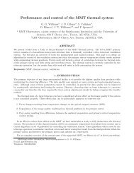
<strong>Toward</strong> <strong>first</strong> <strong>light</strong> <strong>for</strong> <strong>the</strong> <strong>6.5</strong>-m <strong>MMT</strong> <strong>telescope</strong><br />
S. C. West (UA), S. Callahan (<strong>MMT</strong>O), F. H. Chaffee (<strong>MMT</strong>O), W. Davison (UA), S. DeRigne (UA), D. Fabricant (SAO), C. B. Foltz (<strong>MMT</strong>O),<br />
J. M. Hill (UA), R. H. Nagel (UA), A. Poyner (<strong>MMT</strong>O), and J. T. Williams (<strong>MMT</strong>O)<br />
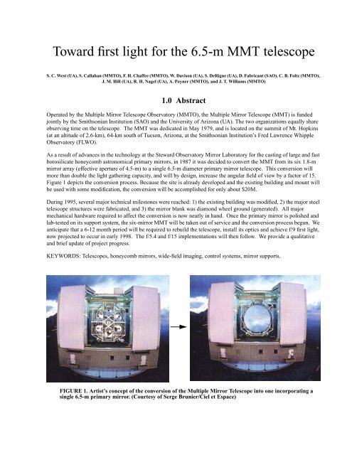
1.0 Abstract<br />
Operated by <strong>the</strong> Multiple Mirror Telescope <strong>Observatory</strong> (<strong>MMT</strong>O), <strong>the</strong> Multiple Mirror Telescope (<strong>MMT</strong>) is funded<br />
jointly by <strong>the</strong> Smithsonian Institution (SAO) and <strong>the</strong> University of Arizona (UA). <strong>The</strong> two organizations equally share<br />
observing time on <strong>the</strong> <strong>telescope</strong>. <strong>The</strong> <strong>MMT</strong> was dedicated in May 1979, and is located on <strong>the</strong> summit of Mt. Hopkins<br />
(at an altitude of 2.6-km), 64-km south of Tucson, Arizona, at <strong>the</strong> Smithsonian Institution’s Fred Lawrence Whipple<br />
<strong>Observatory</strong> (FLWO).<br />
As a result of advances in <strong>the</strong> technology at <strong>the</strong> Steward <strong>Observatory</strong> Mirror Laboratory <strong>for</strong> <strong>the</strong> casting of large and fast<br />
borosilicate honeycomb astronomical primary mirrors, in 1987 it was decided to convert <strong>the</strong> <strong>MMT</strong> from its six 1.8-m<br />
mirror array (effective aperture of 4.5-m) to a single <strong>6.5</strong>-m diameter primary mirror <strong>telescope</strong>. This conversion will<br />
more than double <strong>the</strong> <strong>light</strong> ga<strong>the</strong>ring capacity, and will by design, increase <strong>the</strong> angular field of view by a factor of 15.<br />
Figure 1 depicts <strong>the</strong> conversion process. Because <strong>the</strong> site is already developed and <strong>the</strong> existing building and mount will<br />
be used with some modification, <strong>the</strong> conversion will be accomplished <strong>for</strong> only about $20M.<br />
During 1995, several major technical milestones were reached: 1) <strong>the</strong> existing building was modified, 2) <strong>the</strong> major steel<br />
<strong>telescope</strong> structures were fabricated, and 3) <strong>the</strong> mirror blank was diamond wheel ground (generated). All major<br />
mechanical hardware required to affect <strong>the</strong> conversion is now nearly in hand. Once <strong>the</strong> primary mirror is polished and<br />
lab-tested on its support system, <strong>the</strong> six-mirror <strong>MMT</strong> will be taken out of service and <strong>the</strong> conversion process begun. We<br />
anticipate that a 6-12 month period will be required to rebuild <strong>the</strong> <strong>telescope</strong>, install its optics and achieve f/9 <strong>first</strong> <strong>light</strong>,<br />
now projected to occur in early 1998. <strong>The</strong> f/5.4 and f/15 implementations will <strong>the</strong>n follow. We provide a qualitative<br />
and brief update of project progress.<br />
KEYWORDS: Telescopes, honeycomb mirrors, wide-field imaging, control systems, mirror supports.<br />
FIGURE 1. Artist’s concept of <strong>the</strong> conversion of <strong>the</strong> Multiple Mirror Telescope into one incorporating a<br />
single <strong>6.5</strong>-m primary mirror. (Courtesy of Serge Brunier/Ciel et Espace)
2.0 Optics<br />
<strong>The</strong> <strong>6.5</strong>-m f/1.25 diameter honeycomb borosilicate primary mirror was spun-cast, generated, and is currently being polished<br />
at <strong>the</strong> Steward <strong>Observatory</strong> Mirror Laboratory. 1-2 As shown in Figure 2, <strong>the</strong> <strong>MMT</strong> <strong>6.5</strong>-m will support 5 Casseg-<br />
Vertex height(mm)<br />
8256<br />
7312.060<br />
6919.952<br />
6220.839 w/corrector<br />
6214.426 bare<br />
0.0 primary vertex<br />
-10.526 <strong>first</strong> corrector surface<br />
-1466.85 (mounting)<br />
}<br />
-1778.00 f/9<br />
-1778.33 f/5 spectroscopy<br />
-1784.88 f/5 imaging<br />
-1821.38 f/5 bare<br />
-2286.99 f/15<br />
Prime Focus<br />
f/15 Secondary<br />
f/9 Secondary<br />
f/5 Secondary<br />
Primary mirror<br />
Wide field corrector (imaging)<br />
Instrument mounting surface<br />
Filter/field flattener<br />
Focal plane<br />
FIGURE 2. Cassegrain optical configurations <strong>for</strong> <strong>the</strong> <strong>6.5</strong>-m <strong>MMT</strong> .<br />
rain optical configurations: 1) f/9 with a 13-arcminute diameter FOV -- to make use of existing instrumentation, 2) f/<br />
5.25 with a 5-arcminute FOV, 3) f/5.4 with a corrected 1-degree FOV, 4) fixed/chopping f/15 with a 20-arcminute FOV,<br />
and 5) a fully adaptive f/15. More in<strong>for</strong>mation on <strong>the</strong> optical specifications, design and manufacture of <strong>the</strong>se secondaries<br />
is found in <strong>the</strong>se and o<strong>the</strong>r proceedings. 3-7<br />
<strong>The</strong> large field of view of <strong>the</strong> converted <strong>MMT</strong> at <strong>the</strong> f/5.4 focus is made possible by a large refractive corrector designed<br />
by Harland Epps. All optical surfaces in <strong>the</strong> corrector are ei<strong>the</strong>r spherical or flat, and all elements with optical power<br />
are fused silica. <strong>The</strong> corrector has two optical configurations, one intended <strong>for</strong> spectroscopy and <strong>the</strong> o<strong>the</strong>r intended <strong>for</strong><br />
imaging with large CCD arrays. <strong>The</strong> spectroscopic configuration incorporates atmospheric dispersion compensation<br />
(ADC) prisms, and allows a 1° diameter field. <strong>The</strong> counter-rotating ADC prisms correct <strong>for</strong> atmospheric dispersion<br />
between 1 and 2 airmasses. <strong>The</strong> spectroscopic focal surface is hyperbolic (sag 8-mm), yet highly telecentric to allow<br />
efficient spectroscopy with optical fibers. <strong>The</strong> imaging configuration is <strong>for</strong>med by replacing <strong>the</strong> ADC prisms and <strong>the</strong><br />
rearmost fused silica lens of <strong>the</strong> spectroscopic configuration with ano<strong>the</strong>r fused silica lens (see Figure 3). <strong>The</strong> imaging<br />
focal surface is flat. <strong>The</strong> (0.33--1.0 μm<br />
) polychromatic RMS image diameters are less than 0.50-arcseconds with <strong>the</strong><br />
spectroscopic configuration and less than 0.15-arcseconds with <strong>the</strong> imaging configuration.<br />
Instruments are under construction at SAO to make use of <strong>the</strong> wide fields <strong>for</strong> spectroscopy and imaging. <strong>The</strong> Hectospec<br />
is an optical fiber-fed spectrograph with 300 optical fibers that are reconfigured with tandem high-speed robots. 8 <strong>The</strong><br />
Megacam is a large imager that will use 32 2048 x 4096 pixel CCD's to cover a 22 x 22 arcminute 2 field. 9 O<strong>the</strong>r instru-
FIGURE 3. <strong>The</strong> two f/5.4 wide field imaging modes of <strong>the</strong> <strong>6.5</strong>-m <strong>MMT</strong>. <strong>The</strong> top view is <strong>for</strong> wide-field<br />
spectroscopy and <strong>the</strong> bottom <strong>for</strong> imaging.<br />
ments to operate at <strong>the</strong> f/5 focus include: a high resolution version of <strong>the</strong> Hectospec, <strong>the</strong> Binospec (a large areal spectrograph<br />
addressing dual 6’ x 17’ fields of view), and a triple-beamed (J, H, and K) infrared imager.<br />
3.0 Major steel structures<br />
3.1 Optical support structure and vacuum chamber<br />
<strong>The</strong> firm of Simpson Gumpertz & Heger (SGH) designed <strong>the</strong> major steel components <strong>for</strong> this project. TIW Fabrication<br />
and Machining, Inc. of Albuquerque NM built <strong>the</strong> cell, OSS (Figure 4), and primary mirror vacuum chamber (Figure 4)<br />
and delivered <strong>the</strong>m to Tucson on November 1, 1995. <strong>The</strong> cell was moved into <strong>the</strong> Steward Mirror Lab nadir-pointing to<br />
facilitate metrology and installation of <strong>the</strong> actuator support brackets. After installation, <strong>the</strong> cell was turned zenith-pointing<br />
<strong>for</strong> <strong>the</strong> installation of <strong>the</strong> static supports and ventilation nozzles (Figure 5).<br />
3.2 Building modifications<br />
In order to accommodate <strong>the</strong> increased swing radius of <strong>the</strong> new OSS, <strong>the</strong> existing building lateral and vertical clearance<br />
each needed to be increased by about 2-m (Figure 6). TIW implemented <strong>the</strong> SGH-designed modifications. Following
f/15 fixed hub<br />
f/5 extension<br />
Trunnion ring<br />
Elevation bearing (2)<br />
Elevation drive arc (2)<br />
Trunnion stand (2)<br />
FIGURE 4. <strong>The</strong> completed cell, OSS, and primary mirror vacuum chamber. <strong>The</strong> f/15 hub remains<br />
attached <strong>for</strong> all Cassegrain modes. <strong>The</strong> removable f/5 extension is supported with an extra set of<br />
compression beams which increase stiffness and support <strong>the</strong> cantilever. <strong>The</strong> elevation bearings are an<br />
integral part of <strong>the</strong> trunnion ring. <strong>The</strong>re are two elevation arcs with friction-wheel drives. <strong>The</strong> lower<br />
figure shows <strong>the</strong> vacuum chamber being fitted to <strong>the</strong> cell with <strong>the</strong> <strong>telescope</strong> horizon pointing.<br />
Aluminization will occur in-situ so that <strong>the</strong> primary mirror need never be removed from <strong>the</strong> <strong>telescope</strong>.<br />
Photos by S. Criswell.
FIGURE 5. <strong>The</strong> zenith-pointing <strong>6.5</strong>-m mirror cell in <strong>the</strong> Steward mirror lab. Seen are most of <strong>the</strong> 200<br />
static supports (<strong>the</strong>y define <strong>the</strong> set of axial and lateral resting <strong>for</strong>ces <strong>for</strong> <strong>the</strong> mirror when <strong>the</strong> active<br />
support system is turned off) and <strong>the</strong> 1100+ ventilation air nozzles which squirt air into <strong>the</strong> interiors of<br />
<strong>the</strong> mirror honeycombs and around <strong>the</strong> mirror periphery. <strong>The</strong> vacuum seal flange is visible near <strong>the</strong> ID<br />
of <strong>the</strong> top of <strong>the</strong> trunnion ring.<br />
FIGURE 6. An aerial view of <strong>the</strong> <strong>MMT</strong> building modifications. <strong>The</strong> shutters are lying on <strong>the</strong> ground,<br />
and <strong>the</strong> slit is being enlarged. <strong>The</strong> <strong>telescope</strong> is cocooned with plastic tarp and a wooden top in order to<br />
protect it from <strong>the</strong> modifications and <strong>the</strong> monsoons. Also seen is <strong>the</strong> storage location <strong>for</strong> <strong>the</strong> primary<br />
mirror aluminizing chamber on <strong>the</strong> roof of <strong>the</strong> adjacent building. <strong>The</strong> modifications were completed in<br />
October 1995.<br />
<strong>the</strong> lead of <strong>the</strong> NTT, we also decided to have a 6-m high door put into <strong>the</strong> rear observing chamber wall in order to<br />
improve air circulation and reduce <strong>the</strong> effects of local seeing. Although <strong>the</strong> amount of modification was significant, it<br />
was far less expensive than simply replacing <strong>the</strong> entire rotating building which incorporates machine and electrical<br />
shops, an elevator, and many o<strong>the</strong>r facilities.
4.0 Primary mirror supports and <strong>the</strong>rmal control<br />
<strong>The</strong> primary mirror is positioned in its cell with a Stewart plat<strong>for</strong>m type parallel manipulator consisting of six adjustable<br />
very stiff struts (hardpoints) that connect <strong>the</strong> back plate of <strong>the</strong> cell to <strong>the</strong> back plate of <strong>the</strong> mirror. <strong>The</strong> hardpoints were<br />
designed and built by Studio Technico Tomelleri (Verona, Italy), and were tested at Arcetri <strong>Observatory</strong> by Luciano<br />
Miglietta. 10 One of <strong>the</strong> struts as well as <strong>the</strong> geometrical configuration of <strong>the</strong> Stewart plat<strong>for</strong>m is shown in Figure 7.<br />
FIGURE 7. One of <strong>the</strong> six <strong>MMT</strong> hardpoints (top). <strong>The</strong>y incorporate vane flexures at each end, an in-line<br />
load cell <strong>for</strong> <strong>for</strong>ce feedback of <strong>the</strong> servo system, tension and compression pneumatic high-<strong>for</strong>ce breakaways<br />
<strong>for</strong> protection of <strong>the</strong> mirror, 15-mm of stroke with a resolution of about 1- μm , internal length<br />
encoders, and <strong>the</strong>y maintain a stiffness of over 90- N/μm<br />
. <strong>The</strong> lower figure shows <strong>the</strong> geometrical<br />
arrangement of <strong>the</strong> primary mirror Stewart plat<strong>for</strong>m. <strong>The</strong> hardpoints are connected at three locations<br />
to <strong>the</strong> cell back plate and extend upward to six locations on <strong>the</strong> mirror back plate (mirror not shown).<br />
Drawing by Eric Anderson.<br />
Although <strong>the</strong> hardpoints define <strong>the</strong> precise positioning of <strong>the</strong> primary mirror and provide <strong>the</strong> stiffness of <strong>the</strong> support<br />
system, <strong>the</strong>y operate near zero <strong>for</strong>ce. <strong>The</strong> weight of <strong>the</strong> mirror is supported with 104 pneumatic actuators whose individual<br />
<strong>for</strong>ces are derived from a trans<strong>for</strong>mation required to null <strong>the</strong> six hardpoint <strong>for</strong>ces against gravity and wind load. 11<br />
Details of <strong>the</strong> pneumatic actuators are shown in Figure 8. <strong>The</strong> response of this support system to wind has been estimated<br />
and found to per<strong>for</strong>m well even when pointing directly into a 7-m/s wind. 12
FIGURE 8. Several views of <strong>the</strong> pneumatic primary mirror support system. <strong>The</strong> top shows a side view of<br />
typical single and dual axis actuators. <strong>The</strong>re are 50 dual-, 50 single-axis, and 4 cross-lateral actuators.<br />
<strong>The</strong> center view details how <strong>the</strong> actuators are connected to <strong>the</strong> mirror backplate through a triangular<br />
load spreader. It also shows <strong>the</strong> in-line load cells <strong>for</strong> servo control of <strong>the</strong> <strong>for</strong>ces, and <strong>the</strong> lateral ball<br />
decouplers which insure that <strong>the</strong> actuators don’t bind when <strong>the</strong> mirror changes position. <strong>The</strong> bottom<br />
picture shows one of <strong>the</strong> dual axis actuators attached under <strong>the</strong> cell top plate. Attachments <strong>for</strong> adjacent<br />
actuators can also be seen. (Drawings by Marion McEuen)
Careful attention has been paid to <strong>the</strong> <strong>the</strong>rmal control of <strong>the</strong> primary mirror. Past research has shown that a scheme of<br />
<strong>for</strong>ced-air ventilation into <strong>the</strong> interiors of <strong>the</strong> honeycomb structures works well to maintain a very high quality optical<br />
surface. 13,14 In order to avoid figure distortion, <strong>the</strong> blank must be kept iso<strong>the</strong>rmal to within 0.1°C , and in order to minimize<br />
local seeing effects, it must be kept to within ± 0.15°C of <strong>the</strong> ambient temperature. Temperature slew rates of<br />
2°C/hr must be attained and <strong>the</strong> <strong>the</strong>rmal time constant of <strong>the</strong> mirror can be no more than 45-min. Figure distortion is<br />
controlled by allowing no more than 40-Pa pressure gradient across <strong>the</strong> mirror diameter. Lateral vibrations produce<br />
wavefront tilt, and <strong>the</strong>re<strong>for</strong>e <strong>the</strong> <strong>the</strong>rmal system cannot induce more than 75-nm of lateral vibration which is 10% of <strong>the</strong><br />
diffraction limit at a wavelength of 0.5-μm .<br />
<strong>The</strong> <strong>MMT</strong> will use an array of non-supersonic jet ejectors to achieve this per<strong>for</strong>mance. 15,16 Approximately 150 jet ejectors<br />
similar to those shown in Figure 9 are attached to holes in <strong>the</strong> upper plate of <strong>the</strong> cell. Pressurized and <strong>the</strong>rmally<br />
Ventilation nozzle<br />
Ejector nozzle<br />
Jet ejector (typ.)<br />
Return plenum<br />
Input plenum<br />
FIGURE 9. A prototype jet ejector <strong>for</strong> <strong>the</strong>rmal control of <strong>the</strong> primary mirror (left). At right is a<br />
schematic of <strong>the</strong> <strong>the</strong>rmal system contained in <strong>the</strong> primary mirror cell.<br />
managed air is blown through <strong>the</strong> ejector nozzle which <strong>the</strong>n draws air out of <strong>the</strong> mirror return plenum between <strong>the</strong> cell<br />
top plate and <strong>the</strong> mirror back plate (and hence out of <strong>the</strong> honeycomb cells). <strong>The</strong> two air streams mix in <strong>the</strong> long chamber<br />
and exit and pressurize <strong>the</strong> input plenum in <strong>the</strong> lower part of <strong>the</strong> mirror cell thus <strong>for</strong>cing air through <strong>the</strong> ventilation<br />
nozzles and back into <strong>the</strong> honeycomb cells. Ten-percent of total air volume circulated is pushed through <strong>the</strong> nozzles<br />
and must be “vented” out of <strong>the</strong> cell continuously. Ano<strong>the</strong>r set of 15 jet ejectors exhausts this air into <strong>the</strong> <strong>telescope</strong><br />
chamber and onto <strong>the</strong> <strong>telescope</strong> trunnion ring. <strong>The</strong> jet ejectors generate about 80-Pa of pressure difference across <strong>the</strong><br />
nozzles and so supply about 8-l/s of air volume to each honeycomb cell. Air is supplied to <strong>the</strong> nozzles by an off-board<br />
chiller/blower unit.<br />
5.0 Mount control system<br />
Honeycomb cells<br />
Web plate per<strong>for</strong>ation<br />
<strong>The</strong> azimuth, elevation and instrument rotator axes of <strong>the</strong> <strong>telescope</strong> will be controlled by <strong>the</strong> <strong>MMT</strong> mount servo control<br />
system. Control of each axis is shown in <strong>the</strong> simplified schematic “Servo Loop Diagram” (Figure 10) . <strong>The</strong> outer posi-
FIGURE 10. Schematics of <strong>the</strong> <strong>MMT</strong> servo control system. See text <strong>for</strong> details.<br />
tion loop consists of an input position demand and a position feedback from an on-axis Inductosyn absolute encoder.<br />
<strong>The</strong> resultant position error signal is processed by <strong>the</strong> position loop algorithm to generate a velocity demand properly<br />
clipped so that maximum velocity, acceleration, and jerk are not exceeded. <strong>The</strong> command is <strong>the</strong>n passed to <strong>the</strong> velocity<br />
loop. <strong>The</strong> position loop algorithm is implemented in software, using VxWorks on a Motorola CPU in a VME chassis.<br />
<strong>The</strong> absolute encoder is read and <strong>the</strong> is algorithm computed at 50-Hz.<br />
<strong>The</strong> inner velocity loop consists of <strong>the</strong> velocity demand and velocity feedback derived from an incremental encoder<br />
mounted directly to <strong>the</strong> motor shaft. <strong>The</strong> signals of this digital tachometer are processed by <strong>the</strong> velocity loop algorithm<br />
to produce a torque demand. <strong>The</strong> algorithm is a classical PID control law per<strong>for</strong>med in a hardware motor controller<br />
based on <strong>the</strong> National Semiconductor LM628 chip in an IndustryPack module in a VME carrier board. <strong>The</strong> P, I, and D<br />
parameters are loaded into <strong>the</strong> LM628 from software in <strong>the</strong> VME CPU and may be changed dynamically. <strong>The</strong> velocity<br />
loop operates at ~4-kHz passing <strong>the</strong> torque command to <strong>the</strong> amplifiers and hence to <strong>the</strong> motors.<br />
Four motors are used on <strong>the</strong> azimuth drive -- each with its own amplifier driving a common bull gear through gearboxes.<br />
<strong>The</strong> motors are in two pairs, and <strong>the</strong> motors of each pair are biased against each o<strong>the</strong>r to minimize backlash. This provides<br />
a “stiff” system, and we anticipate that <strong>the</strong> velocity of all of <strong>the</strong> motors will be <strong>the</strong> same. <strong>The</strong>re<strong>for</strong>e, we can use an<br />
incremental encoder on just one motor as <strong>the</strong> velocity feedback, so <strong>the</strong> torque demand from one motor controller is fed<br />
to all <strong>the</strong> amplifiers.<br />
In elevation however, <strong>the</strong> <strong>6.5</strong>-m <strong>MMT</strong> will have two motors, each friction-coupled to a drive arc on opposite sides of <strong>the</strong><br />
<strong>telescope</strong>. Anticipating <strong>the</strong> possibility of flexing between <strong>the</strong> arcs led us to design <strong>for</strong> incremental encoders on each
motor, feeding back to two LM628 motor controllers. <strong>The</strong> position feedback is from one absolute encoder on-axis, so<br />
one position loop algorithm feeds <strong>the</strong> same velocity demand into both controllers.<br />
<strong>The</strong> block diagram (lower part of Figure 10), shows <strong>the</strong> basic hardware layout of <strong>the</strong> mount control system. A Sun<br />
workstation provides a graphical user interface <strong>for</strong> <strong>the</strong> <strong>telescope</strong> operator. Position commands in <strong>the</strong> <strong>for</strong>m of currentepoch<br />
RA and Dec coordinates are sent to <strong>the</strong> Motorola CPU in a VME crate, and status in<strong>for</strong>mation is received and<br />
displayed on <strong>the</strong> Sun.<br />
<strong>The</strong> mount control program, running under VxWorks in <strong>the</strong> VME computer, converts <strong>the</strong> RA/Dec input to demanded<br />
azimuth, elevation and rotator angles, reads <strong>the</strong> absolute encoders through parallel interface modules, and calculates <strong>the</strong><br />
position loop algorithms. <strong>The</strong> demanded velocities are passed on <strong>the</strong> VME backplane to <strong>the</strong> LM628 controllers residing<br />
in <strong>the</strong> same crate. Between <strong>the</strong> VME crate and <strong>the</strong> <strong>telescope</strong>, we have a Mount Interface Chassis -- an in-house built<br />
unit to provide isolation and line-driving capabilities. This is physically close to <strong>the</strong> VME to minimize <strong>the</strong> effect of<br />
<strong>light</strong>ning-induced transients. <strong>The</strong> encoder box is placed close to <strong>the</strong> encoder in order to minimize noise degradation of<br />
<strong>the</strong> analog signals produced by <strong>the</strong> Inductosyn encoders. This box houses resolver-to-digital converters and <strong>the</strong> encoder<br />
excitation oscillators. <strong>The</strong> output from this box is <strong>the</strong>n a parallel digital signal which is noise-immune.<br />
6.0 Acknowledgments<br />
We recognize <strong>the</strong> enormous ef<strong>for</strong>ts of <strong>the</strong> <strong>MMT</strong>O staff, <strong>the</strong> Steward <strong>Observatory</strong> Mirror Laboratory, <strong>the</strong> Steward <strong>Observatory</strong><br />
technical division, Arcetri <strong>Observatory</strong>, Harland Epps, Bob Fata, Irwin Shapiro, and Peter Strittmatter.<br />
7.0 References<br />
1. B. H. Olbert, J. R. P. Angel, J. M. Hill, and S. F. Hinman 1994, “Casting <strong>6.5</strong>-m mirrors <strong>for</strong> <strong>the</strong> <strong>MMT</strong> Conversion and<br />
Magellan”, Advanced Technology Optical Telescopes V, Proc. SPIE 2199, 144-155.<br />
2. B. M. Martin, J. H. Burge, D. A. Ketelsen, and S. C. West 1996, “Fabrication of <strong>the</strong> <strong>6.5</strong>-m primary mirror <strong>for</strong> <strong>the</strong><br />
Multiple Mirror Telescope Conversion”, Proc. this conference.<br />
3. Peter Gray, S. C. West, and W. Gallieni 1996, “Support and actuation of six secondaries <strong>for</strong> <strong>the</strong> <strong>6.5</strong>-m <strong>MMT</strong> and 8.4m<br />
LBT <strong>telescope</strong>s”, Proc. this conference.<br />
4. Jim Burge 1996, “Measurement of large convex secondary mirrors”, Proc. this conference.<br />
5. D. Fabricant and B. McLeod 1996, “Optical specifications <strong>for</strong> <strong>the</strong> <strong>MMT</strong> conversion”, preprint of a <strong>for</strong>thcoming<br />
<strong>MMT</strong> Conversion Technical Report.<br />
6. R. Fata and D. Fabricant 1994, “<strong>The</strong> design and support of <strong>the</strong> 1.7-m f/5 secondary mirror <strong>for</strong> <strong>the</strong> <strong>MMT</strong> conversion”,<br />
Advanced Technology Optical Telescopes V, Proc. SPIE 2199, 580-592.<br />
7. D. G. Bruns, T. K. Barrett, D. G. Sandler, H. M. Martin, and G. Brusa 1996, “<strong>MMT</strong> adaptive secondary mirror concave<br />
prototype”, Proc. this conference.<br />
8. D. Fabricant, E. Hertz, and A. Szentgyorgy 1994, “Hectospec: a 300-optical-fiber spectrograph <strong>for</strong> <strong>the</strong> converted<br />
<strong>MMT</strong>”, Proc. SPIE 2198, 251-263.<br />
9. B. McLeod, D. Fabricant, J. Geary, and A. Szentgyorgy 1996, Wide-field CCD imager <strong>for</strong> <strong>the</strong> <strong>6.5</strong>-m <strong>MMT</strong> <strong>telescope</strong>”,<br />
Proc. SPIE 2654, 233-238.<br />
10. L. Miglietta 1996, “<strong>The</strong> position actuators of <strong>the</strong> 8.4-m LBT primary mirrors”, Proc. this conference.<br />
11. J. M. Hill 1995, “Mirror support system <strong>for</strong> large honeycomb mirrors II/R”, LBT Project Technical Memo, UA-95-<br />
02.<br />
12. S. C. West and H. M. Martin 1995, “Approximate wind disturbance of <strong>the</strong> <strong>MMT</strong> <strong>6.5</strong>-m primary mirror on its supports”,<br />
Multiple Mirror Telescope Technical Report #28, University of Arizona and <strong>the</strong> Smithsonian Institution.
13. J. R. P. Angel, A. Y. S. Cheng, and N. J. Woolf 1988, “<strong>The</strong>rmal stabilization of honeycomb mirrors”, in Proc. ESO<br />
Very Large Telescopes and <strong>The</strong>ir Instrumentation, ed. M. H. Ulrich, 467.<br />
14. M. Lloyd-Hart 1990, “System <strong>for</strong> precise temperature sensing and <strong>the</strong>rmal control of borosilicate honeycomb mirros<br />
during polishing and testing”, Advanced Technology Optical Telescopes IV, Proc. SPIE 1236, ed. L. D. Barr,<br />
844.<br />
15. L. Miglietta 1991, “Primary mirror temperature control system: feasibility study of an air-air ejector device”,<br />
Arcetri Technical Report 09-1991, Arcetri <strong>Observatory</strong>.<br />
16. L. Miglietta April 1992, “Air-air ejector <strong>for</strong> large mirror temperature control: numerical simulations and experimental<br />
data”, Progress in Telescope and Instrumentation Technologies, Proc. ESO, Garching, 361-364.