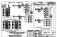
Toward first light for the 6.5-m MMT telescope - The MMT Observatory
Toward first light for the 6.5-m MMT telescope - The MMT Observatory
Toward first light for the 6.5-m MMT telescope - The MMT Observatory

You also want an ePaper? Increase the reach of your titles
YUMPU automatically turns print PDFs into web optimized ePapers that Google loves.
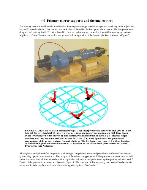
4.0 Primary mirror supports and <strong>the</strong>rmal control<br />
<strong>The</strong> primary mirror is positioned in its cell with a Stewart plat<strong>for</strong>m type parallel manipulator consisting of six adjustable<br />
very stiff struts (hardpoints) that connect <strong>the</strong> back plate of <strong>the</strong> cell to <strong>the</strong> back plate of <strong>the</strong> mirror. <strong>The</strong> hardpoints were<br />
designed and built by Studio Technico Tomelleri (Verona, Italy), and were tested at Arcetri <strong>Observatory</strong> by Luciano<br />
Miglietta. 10 One of <strong>the</strong> struts as well as <strong>the</strong> geometrical configuration of <strong>the</strong> Stewart plat<strong>for</strong>m is shown in Figure 7.<br />
FIGURE 7. One of <strong>the</strong> six <strong>MMT</strong> hardpoints (top). <strong>The</strong>y incorporate vane flexures at each end, an in-line<br />
load cell <strong>for</strong> <strong>for</strong>ce feedback of <strong>the</strong> servo system, tension and compression pneumatic high-<strong>for</strong>ce breakaways<br />
<strong>for</strong> protection of <strong>the</strong> mirror, 15-mm of stroke with a resolution of about 1- μm , internal length<br />
encoders, and <strong>the</strong>y maintain a stiffness of over 90- N/μm<br />
. <strong>The</strong> lower figure shows <strong>the</strong> geometrical<br />
arrangement of <strong>the</strong> primary mirror Stewart plat<strong>for</strong>m. <strong>The</strong> hardpoints are connected at three locations<br />
to <strong>the</strong> cell back plate and extend upward to six locations on <strong>the</strong> mirror back plate (mirror not shown).<br />
Drawing by Eric Anderson.<br />
Although <strong>the</strong> hardpoints define <strong>the</strong> precise positioning of <strong>the</strong> primary mirror and provide <strong>the</strong> stiffness of <strong>the</strong> support<br />
system, <strong>the</strong>y operate near zero <strong>for</strong>ce. <strong>The</strong> weight of <strong>the</strong> mirror is supported with 104 pneumatic actuators whose individual<br />
<strong>for</strong>ces are derived from a trans<strong>for</strong>mation required to null <strong>the</strong> six hardpoint <strong>for</strong>ces against gravity and wind load. 11<br />
Details of <strong>the</strong> pneumatic actuators are shown in Figure 8. <strong>The</strong> response of this support system to wind has been estimated<br />
and found to per<strong>for</strong>m well even when pointing directly into a 7-m/s wind. 12