Toward first light for the 6.5-m MMT telescope - The MMT Observatory
Toward first light for the 6.5-m MMT telescope - The MMT Observatory
Toward first light for the 6.5-m MMT telescope - The MMT Observatory

Create successful ePaper yourself
Turn your PDF publications into a flip-book with our unique Google optimized e-Paper software.
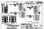
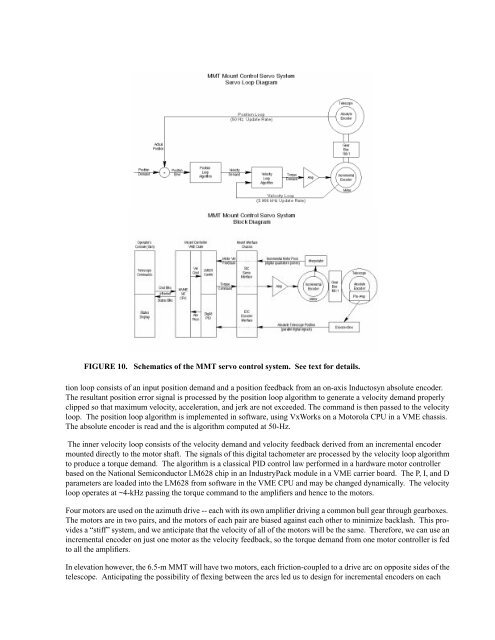
FIGURE 10. Schematics of <strong>the</strong> <strong>MMT</strong> servo control system. See text <strong>for</strong> details.<br />
tion loop consists of an input position demand and a position feedback from an on-axis Inductosyn absolute encoder.<br />
<strong>The</strong> resultant position error signal is processed by <strong>the</strong> position loop algorithm to generate a velocity demand properly<br />
clipped so that maximum velocity, acceleration, and jerk are not exceeded. <strong>The</strong> command is <strong>the</strong>n passed to <strong>the</strong> velocity<br />
loop. <strong>The</strong> position loop algorithm is implemented in software, using VxWorks on a Motorola CPU in a VME chassis.<br />
<strong>The</strong> absolute encoder is read and <strong>the</strong> is algorithm computed at 50-Hz.<br />
<strong>The</strong> inner velocity loop consists of <strong>the</strong> velocity demand and velocity feedback derived from an incremental encoder<br />
mounted directly to <strong>the</strong> motor shaft. <strong>The</strong> signals of this digital tachometer are processed by <strong>the</strong> velocity loop algorithm<br />
to produce a torque demand. <strong>The</strong> algorithm is a classical PID control law per<strong>for</strong>med in a hardware motor controller<br />
based on <strong>the</strong> National Semiconductor LM628 chip in an IndustryPack module in a VME carrier board. <strong>The</strong> P, I, and D<br />
parameters are loaded into <strong>the</strong> LM628 from software in <strong>the</strong> VME CPU and may be changed dynamically. <strong>The</strong> velocity<br />
loop operates at ~4-kHz passing <strong>the</strong> torque command to <strong>the</strong> amplifiers and hence to <strong>the</strong> motors.<br />
Four motors are used on <strong>the</strong> azimuth drive -- each with its own amplifier driving a common bull gear through gearboxes.<br />
<strong>The</strong> motors are in two pairs, and <strong>the</strong> motors of each pair are biased against each o<strong>the</strong>r to minimize backlash. This provides<br />
a “stiff” system, and we anticipate that <strong>the</strong> velocity of all of <strong>the</strong> motors will be <strong>the</strong> same. <strong>The</strong>re<strong>for</strong>e, we can use an<br />
incremental encoder on just one motor as <strong>the</strong> velocity feedback, so <strong>the</strong> torque demand from one motor controller is fed<br />
to all <strong>the</strong> amplifiers.<br />
In elevation however, <strong>the</strong> <strong>6.5</strong>-m <strong>MMT</strong> will have two motors, each friction-coupled to a drive arc on opposite sides of <strong>the</strong><br />
<strong>telescope</strong>. Anticipating <strong>the</strong> possibility of flexing between <strong>the</strong> arcs led us to design <strong>for</strong> incremental encoders on each