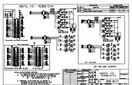
motor, feeding back to two LM628 motor controllers. <strong>The</strong> position feedback is from one absolute encoder on-axis, so one position loop algorithm feeds <strong>the</strong> same velocity demand into both controllers. <strong>The</strong> block diagram (lower part of Figure 10), shows <strong>the</strong> basic hardware layout of <strong>the</strong> mount control system. A Sun workstation provides a graphical user interface <strong>for</strong> <strong>the</strong> <strong>telescope</strong> operator. Position commands in <strong>the</strong> <strong>for</strong>m of currentepoch RA and Dec coordinates are sent to <strong>the</strong> Motorola CPU in a VME crate, and status in<strong>for</strong>mation is received and displayed on <strong>the</strong> Sun. <strong>The</strong> mount control program, running under VxWorks in <strong>the</strong> VME computer, converts <strong>the</strong> RA/Dec input to demanded azimuth, elevation and rotator angles, reads <strong>the</strong> absolute encoders through parallel interface modules, and calculates <strong>the</strong> position loop algorithms. <strong>The</strong> demanded velocities are passed on <strong>the</strong> VME backplane to <strong>the</strong> LM628 controllers residing in <strong>the</strong> same crate. Between <strong>the</strong> VME crate and <strong>the</strong> <strong>telescope</strong>, we have a Mount Interface Chassis -- an in-house built unit to provide isolation and line-driving capabilities. This is physically close to <strong>the</strong> VME to minimize <strong>the</strong> effect of <strong>light</strong>ning-induced transients. <strong>The</strong> encoder box is placed close to <strong>the</strong> encoder in order to minimize noise degradation of <strong>the</strong> analog signals produced by <strong>the</strong> Inductosyn encoders. This box houses resolver-to-digital converters and <strong>the</strong> encoder excitation oscillators. <strong>The</strong> output from this box is <strong>the</strong>n a parallel digital signal which is noise-immune. 6.0 Acknowledgments We recognize <strong>the</strong> enormous ef<strong>for</strong>ts of <strong>the</strong> <strong>MMT</strong>O staff, <strong>the</strong> Steward <strong>Observatory</strong> Mirror Laboratory, <strong>the</strong> Steward <strong>Observatory</strong> technical division, Arcetri <strong>Observatory</strong>, Harland Epps, Bob Fata, Irwin Shapiro, and Peter Strittmatter. 7.0 References 1. B. H. Olbert, J. R. P. Angel, J. M. Hill, and S. F. Hinman 1994, “Casting <strong>6.5</strong>-m mirrors <strong>for</strong> <strong>the</strong> <strong>MMT</strong> Conversion and Magellan”, Advanced Technology Optical Telescopes V, Proc. SPIE 2199, 144-155. 2. B. M. Martin, J. H. Burge, D. A. Ketelsen, and S. C. West 1996, “Fabrication of <strong>the</strong> <strong>6.5</strong>-m primary mirror <strong>for</strong> <strong>the</strong> Multiple Mirror Telescope Conversion”, Proc. this conference. 3. Peter Gray, S. C. West, and W. Gallieni 1996, “Support and actuation of six secondaries <strong>for</strong> <strong>the</strong> <strong>6.5</strong>-m <strong>MMT</strong> and 8.4m LBT <strong>telescope</strong>s”, Proc. this conference. 4. Jim Burge 1996, “Measurement of large convex secondary mirrors”, Proc. this conference. 5. D. Fabricant and B. McLeod 1996, “Optical specifications <strong>for</strong> <strong>the</strong> <strong>MMT</strong> conversion”, preprint of a <strong>for</strong>thcoming <strong>MMT</strong> Conversion Technical Report. 6. R. Fata and D. Fabricant 1994, “<strong>The</strong> design and support of <strong>the</strong> 1.7-m f/5 secondary mirror <strong>for</strong> <strong>the</strong> <strong>MMT</strong> conversion”, Advanced Technology Optical Telescopes V, Proc. SPIE 2199, 580-592. 7. D. G. Bruns, T. K. Barrett, D. G. Sandler, H. M. Martin, and G. Brusa 1996, “<strong>MMT</strong> adaptive secondary mirror concave prototype”, Proc. this conference. 8. D. Fabricant, E. Hertz, and A. Szentgyorgy 1994, “Hectospec: a 300-optical-fiber spectrograph <strong>for</strong> <strong>the</strong> converted <strong>MMT</strong>”, Proc. SPIE 2198, 251-263. 9. B. McLeod, D. Fabricant, J. Geary, and A. Szentgyorgy 1996, Wide-field CCD imager <strong>for</strong> <strong>the</strong> <strong>6.5</strong>-m <strong>MMT</strong> <strong>telescope</strong>”, Proc. SPIE 2654, 233-238. 10. L. Miglietta 1996, “<strong>The</strong> position actuators of <strong>the</strong> 8.4-m LBT primary mirrors”, Proc. this conference. 11. J. M. Hill 1995, “Mirror support system <strong>for</strong> large honeycomb mirrors II/R”, LBT Project Technical Memo, UA-95- 02. 12. S. C. West and H. M. Martin 1995, “Approximate wind disturbance of <strong>the</strong> <strong>MMT</strong> <strong>6.5</strong>-m primary mirror on its supports”, Multiple Mirror Telescope Technical Report #28, University of Arizona and <strong>the</strong> Smithsonian Institution.
13. J. R. P. Angel, A. Y. S. Cheng, and N. J. Woolf 1988, “<strong>The</strong>rmal stabilization of honeycomb mirrors”, in Proc. ESO Very Large Telescopes and <strong>The</strong>ir Instrumentation, ed. M. H. Ulrich, 467. 14. M. Lloyd-Hart 1990, “System <strong>for</strong> precise temperature sensing and <strong>the</strong>rmal control of borosilicate honeycomb mirros during polishing and testing”, Advanced Technology Optical Telescopes IV, Proc. SPIE 1236, ed. L. D. Barr, 844. 15. L. Miglietta 1991, “Primary mirror temperature control system: feasibility study of an air-air ejector device”, Arcetri Technical Report 09-1991, Arcetri <strong>Observatory</strong>. 16. L. Miglietta April 1992, “Air-air ejector <strong>for</strong> large mirror temperature control: numerical simulations and experimental data”, Progress in Telescope and Instrumentation Technologies, Proc. ESO, Garching, 361-364.