


You also want an ePaper? Increase the reach of your titles
YUMPU automatically turns print PDFs into web optimized ePapers that Google loves.
<strong>EVAL</strong>-<strong>AD1852EB</strong><br />
FUNCTIONAL DESCRIPTION<br />
The AD1852 evaluation board presents a reference design that<br />
can be used as a suggested layout and circuit implementation,<br />
which will deliver optimal performance from the audio DAC. As<br />
far as is possible on an evaluation board, current assembly methods<br />
and components are used. Most components are surface mount<br />
devices and a four-layer printed circuit board is used with full<br />
internal power and ground planes for best noise performance.<br />
For guidance, a schematic, bill of materials, PLD source code,<br />
and PCB plots are included in this document.<br />
POWER SUPPLIES<br />
The PC board is divided into analog and digital sections, each<br />
with separate power supplies, to facilitate testing. The digital<br />
power supply input is via binding post terminals J8 and J9. The<br />
recommended digital supply is 12 V dc at 110 mA ± 25 mA. An<br />
on-board voltage regulator (U6) provides 5 V dc, ± 5% to the<br />
digital circuitry. The analog power supply inputs are binding<br />
posts, J10, J11, and J12. Recommended analog supply is 12 V<br />
dc at 50 mA ± 10 mA and –12 V dc at –20 ± 5 mA. An onboard,<br />
low noise voltage regulator, (U7) provides 5 V dc, ± 5%<br />
to the analog power pins of the AD1852 DAC.<br />
DIGITAL AUDIO SIGNAL INPUTS<br />
RCA phone jack, (J1) and optical TOSLink input (U1) may be<br />
used for standard SPDIF or AES/EBU input signals. J1 is terminated<br />
with a 75 Ω resistor. Switch S1 selects between J1 and U1<br />
inputs and feeds the selected signal to the digital interface receiver<br />
(U2). Switch SPDIF/EXT (S3) controls CPLD (U4) and U11,<br />
which is used to switch signals between the SPDIF input (J1)<br />
and the direct input, via the 10-pin header J2, EXT DATA<br />
INTERFACE.<br />
The EXT DATA INTERFACE input permits buffered (U4,<br />
M4–64/32 and U11, HC00) access to the BCLK, L/RCLK,<br />
SDATA and MCLK inputs to the AD1852 DAC. This permits<br />
testing with left-justified, I2S or right-justified, serial input modes.<br />
Note that with right-justified input data, the AD1852 control<br />
register must be programmed for the correct number of data<br />
bits, i.e., 16, 20 or 24 bits. When using the direct input header,<br />
it is necessary to provide all four signals, MCLK, BCLK, L/RCLK<br />
and SDATA. A termination network (RC1), consisting of a series<br />
connected 100 Ω resistor and a 47 pF capacitor, is shunted<br />
across each signal line to reduce line reflections. A 10 kΩ pullup<br />
network (RT1) ensures the inputs are not floating in the<br />
absence of an external data source.<br />
EXTERNAL SPI CONTROL PORT<br />
An external control port, SPI CONTROL PORT (J3), is provided,<br />
via a 10-pin header, so that the internal volume controls<br />
and control registers can be programmed from an external host<br />
or microcontroller. This port accepts serial data to independently<br />
set the left/right volume or the operating mode of the<br />
AD1852 by programming the contents of three internal 16-bit<br />
registers. When setting the volume, a 16-bit control word has<br />
14 bits allocated to the left or right volume control, giving a<br />
total range of 84 dB. Details of the signal format and timing are<br />
discussed in the AD1852 data sheet.<br />
–2–<br />
An additional connector, PC PORT (J5), has been provided to<br />
permit connection to the parallel port of a computer. A termination<br />
network (RC2) consisting of a series-connected 100 Ω<br />
resistor and a 47 pF capacitor, is shunted across each signal line<br />
to reduce line reflections. Additionally, a Schmitt trigger (U5)<br />
reduces the effects of noise and line reflections. A 10 kΩ pull-up<br />
network (RT2) ensures the inputs are not floating in the absence<br />
of an external data source.<br />
PC LabView software (LV<strong>AD1852EB</strong>.zip) can be downloaded<br />
from the <strong>Analog</strong> <strong>Devices</strong>, Inc., Digital Audio website, (http://<br />
www.analog.com/techsupt/eb/lin_eb/ad1852/ad1852.html) to<br />
program the internal control registers and set the left and right<br />
volume levels. An interface cable connects between the PC<br />
parallel printer port (LPTn) 25-pin Dsub connector and the<br />
9-pin Dsub (J5) connector on the evaluation board. A suitable<br />
cable is Belkin Modem cable, part number 589604, F2L088-06<br />
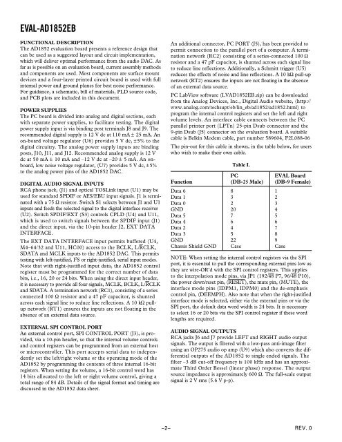
The pin-out for this cable in shown, in the table below, for users<br />
who wish to make their own cable.<br />
Table I.<br />
PC <strong>EVAL</strong> Board<br />
Function (DB-25 Male) (DB-9 Female)<br />
Data 6 8 1<br />
Data 1 3 2<br />
Data 0 2 3<br />
GND 20 4<br />
Data 5 7 5<br />
Data 4 6 6<br />
Data 2 4 7<br />
Data 3 5 8<br />
GND 22 9<br />
Chassis Shield GND Case Case<br />
NOTE: When setting the internal control registers via the SPI<br />
port, it is essential to pull the corresponding external pins low as<br />
they are wire-OR’d with the SPI control registers. This applies<br />
to the interpolation mode pins, via JP1 (192/48 P7, 96/48 P10),<br />
the power down/reset pin, (RESET), the mute pin, (MUTE), the<br />
interface mode pins (IDPM1, IDPM0) and the de-emphasis<br />
control pin, (DEEMPH). Also note that when the right-justified<br />
interface mode is selected, either via the external pins or via the<br />
SPI port, the default data word width is 24 bits. It is necessary<br />
to select 16 or 20 bits via the SPI control register if these word<br />
lengths are required.<br />
AUDIO SIGNAL OUTPUTS<br />
RCA jacks J6 and J7 provide LEFT and RIGHT audio output<br />
signals. The output is filtered with a low-pass anti-image filter<br />
using an OP275 audio op amp (U9) which also converts the differential<br />
outputs of the AD1852 to single ended signals. The<br />
filter –3 dB cut-off frequency is 100 kHz and has an approximate<br />
Third Order Bessel (linear phase) response. The output<br />
source impedance is approximately 600 Ω. The full-scale output<br />
signal is 2 V rms (5.6 V p-p).<br />
REV. 0


