Gearshift-Comfort Oriented Transmission and Drive Train Simulation ...
Gearshift-Comfort Oriented Transmission and Drive Train Simulation ...
Gearshift-Comfort Oriented Transmission and Drive Train Simulation ...

Create successful ePaper yourself
Turn your PDF publications into a flip-book with our unique Google optimized e-Paper software.
Editor<br />
INTEC GmbH, Argelsrieder Feld 13, 82234 Wessling, Germany<br />
VOLUME 9, FIRST ISSUE<br />
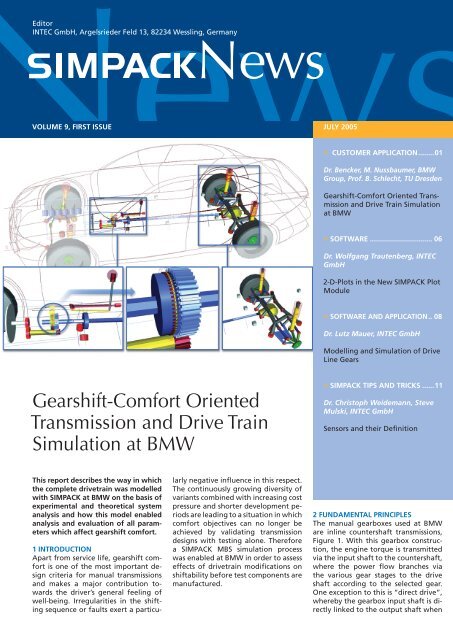
<strong>Gearshift</strong>-<strong>Comfort</strong> <strong>Oriented</strong><br />
<strong>Transmission</strong> <strong>and</strong> <strong>Drive</strong> <strong>Train</strong><br />
<strong>Simulation</strong> at BMW<br />
This report describes the way in which<br />
the complete drivetrain was modelled<br />
with SIMPACK at BMW on the basis of<br />
experimental <strong>and</strong> theoretical system<br />
analysis <strong>and</strong> how this model enabled<br />
analysis <strong>and</strong> evaluation of all parameters<br />
which affect gearshift comfort.<br />
1 INTRODUCTION<br />
Apart from service life, gearshift comfort<br />
is one of the most important design<br />
criteria for manual transmissions<br />
<strong>and</strong> makes a major contribution towards<br />
the driver’s general feeling of<br />
well-being. Irregularities in the shifting<br />
sequence or faults exert a particu-<br />
larly negative infl uence in this respect.<br />
The continuously growing diversity of<br />
variants combined with increasing cost<br />
pressure <strong>and</strong> shorter development periods<br />
are leading to a situation in which<br />
comfort objectives can no longer be<br />
achieved by validating transmission<br />
designs with testing alone. Therefore<br />
a SIMPACK MBS simulation process<br />
was enabled at BMW in order to assess<br />
effects of drivetrain modifi cations on<br />
shiftability before test components are<br />
manufactured.<br />
JULY 2005<br />
» CUSTOMER APPLICATION ........01<br />
Dr. Bencker, M. Nussbaumer, BMW<br />
Group, Prof. B. Schlecht, TU Dresden<br />
<strong>Gearshift</strong>-<strong>Comfort</strong> <strong>Oriented</strong> <strong>Transmission</strong><br />
<strong>and</strong> <strong>Drive</strong> <strong>Train</strong> <strong>Simulation</strong><br />
at BMW<br />
» SOFTWARE ............................... 06<br />
Dr. Wolfgang Trautenberg, INTEC<br />
GmbH<br />
2-D-Plots in the New SIMPACK Plot<br />
Module<br />
» SOFTWARE AND APPLICATION .. 08<br />
Dr. Lutz Mauer, INTEC GmbH<br />
Modelling <strong>and</strong> <strong>Simulation</strong> of <strong>Drive</strong><br />
Line Gears<br />
» SIMPACK TIPS AND TRICKS ......11<br />
Dr. Christoph Weidemann, Steve<br />
Mulski, INTEC GmbH<br />
Sensors <strong>and</strong> their Defi nition<br />
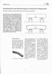
2 FUNDAMENTAL PRINCIPLES<br />
The manual gearboxes used at BMW<br />
are inline countershaft transmissions,<br />
Figure 1. With this gearbox construction,<br />
the engine torque is transmitted<br />
via the input shaft to the countershaft,<br />
where the power fl ow branches via<br />
the various gear stages to the drive<br />
shaft according to the selected gear.<br />
One exception to this is “direct drive”,<br />
whereby the gearbox input shaft is directly<br />
linked to the output shaft when
» CUSTOMER APPLICATION<br />
Dr. Bencker, M. Nussbaumer, BMW<br />
Group, Prof. B. Schlecht, TU Dresden<br />
Figure 1: Inline Countershaft <strong>Transmission</strong>s<br />
<strong>and</strong> Synchroniser<br />
Figure 2: Positive of the Synchroniser<br />
showing the fi ve Phases of the<br />
Synchronisation Sequence<br />
the gear is selected. When changing<br />
gear, the driver uses the gear lever to<br />
activate the synchromesh mechanism<br />
with the clutch pedal pressed down.<br />
The gearshift effort is applied to the<br />
sliding sleeve of the synchroniser via<br />
the external <strong>and</strong> internal shift mechanisms<br />
<strong>and</strong> the desired gear is selected.<br />
2.1 SYNCHRONISER<br />
The synchroniser, Figure 1, is used to<br />
accelerate or decelerate the gear set<br />
(with clutch disk) from the current<br />
gear level to the speed of the target<br />
gear, enabling gear selection. Positive<br />
locking is then established during the<br />
subsequent phase <strong>and</strong> the gear is engaged.<br />
The synchronisation sequence can be<br />
divided into 5 phases, which are refl<br />
ected in the gearshift effort profi le<br />
at the gear lever, Figure 3.<br />
Joined to the fi xed sleeve with a torsion<br />
resistant connection, the sliding<br />
sleeve is in its neutral position during<br />
Phase I <strong>and</strong> the driver pushes it towards<br />
the gear wheel to be selected,<br />
Figure 2, Phase I. Pre-synchronisation<br />
is achieved by the thrust pieces which<br />
move the synchroniser ring into the<br />
blocked position. This is perceived as a<br />
slight increase in gearshift effort, Figure<br />
3, Phase I.<br />
Phase II is referred to as the synchronising<br />
phase. The sliding sleeve presses<br />
the synchroniser ring against the friction<br />
cone of the synchroniser hub, Figure<br />
2, Phase II, while the rpm of the<br />
gear set is matched to the speed of the<br />
target gear by means of one or several<br />
friction surfaces. The gearshift effort<br />
increases again rapidly during this<br />
phase, Figure 3, Phase II.<br />
Once synchronism is achieved, the<br />
torque between the mating surfaces<br />
tends towards zero <strong>and</strong> the synchroniser<br />
ring can rotate freely again, Figure<br />
2, Phase III. This eliminates the blocking<br />
effect <strong>and</strong> the free-fl ight phase<br />
(Phase III) begins. This process is evident<br />
as a noticeable dip in the effort<br />
profi le, Figure 3, Phase III. In Phase III,<br />
the sliding sleeve again moves towards<br />
the gear wheel until it makes contact<br />
with the synchroniser hub, initiating<br />
SIMPACK»News, July 2005<br />
2<br />
Phase IV.<br />
The resulting impact, Figure 2, Phase<br />
IV, is transmitted via the internal <strong>and</strong><br />
external shift mechanisms to the driver‘s<br />
h<strong>and</strong> <strong>and</strong> is shown as an impulse<br />
in the gearshift effort profi le, also referred<br />
to as the double bump, Figure<br />
3, Phase IV.<br />
Phase V, in which the gear is engaged,<br />
begins when the bevels on the teeth<br />
of the synchroniser hub have been<br />
overcome. The renewed increase in<br />
gearshift effort is due to the sliding<br />
sleeve making contact with the end<br />
stop, Figure 3, Phase V.<br />
3 PROBLEMS ENCOUNTERED IN THE<br />
SHIFTING SEQUENCE<br />
Shifting Sequence Reference literature<br />
describes four known synchroniser related<br />
types of problem occurring in the<br />
shifting sequence, which are perceived<br />
by the driver acoustically or in the<br />
gearshift effort profi le at the gear lever.<br />
These phenomena are unblocking<br />
inhibition, meshing inhibition, double<br />
bump <strong>and</strong> vibration grating. The fi rst<br />
three are static problems <strong>and</strong> can be<br />
infl uenced by geometric synchroniser<br />
variables (cone angle, sharpness of selector<br />
teeth, etc.), for example. Unlike<br />
these, vibration grating is essentially<br />
determined by the dynamic performance<br />
of the entire drive train, as well<br />
as geometric transmission variables<br />
<strong>and</strong> the synchroniser. The reciprocal<br />
infl uences of gearbox, drive train <strong>and</strong><br />
vehicle on the shifting sequence lead<br />
to numerous interactive effects <strong>and</strong><br />
goal confl icts, which are very diffi cult<br />
to defi ne in terms of testing, which is<br />
why simulation is used to examine this<br />
vibration phenomenon.<br />
3.1 DESCRIPTION OF THE “VIBRATION<br />
GRATING” PHENOMENON<br />
The continuous increase in engine<br />
torque is accompanied by an increasing<br />
load on the drive train components<br />
(clutch, gearbox, etc.). The effects are<br />
inevitably felt in their size <strong>and</strong>, above<br />
all, in the inertia of their masses. In an<br />
effort to achieve short shifting times<br />
with low gearshift effort, effi cient<br />
multi-cone synchronisers are used, en-
abling acceleration or deceleration of<br />
the inert gear set to the level of the<br />
target gear. The resulting high synchronising<br />
torque – particularly when<br />
changing down from 2nd to 1st gear<br />
– is supported by the drive train, which<br />
is twisted as a result. In the free-fl ight<br />
phase, when the synchronising torque<br />
drops to 0 Nm, the drive train settles<br />
back within its elasticity <strong>and</strong> backlash<br />
limits. This leads to another difference<br />
between the speeds of the sliding<br />
sleeve linked to the output shaft in 1st<br />
gear <strong>and</strong> the synchroniser hub, which<br />
is linked to the gear set <strong>and</strong> rotates<br />
at virtually constant speed. When the<br />
sliding sleeve makes contact with the<br />
synchroniser hub (Phase IV) during a<br />
grating gear shift, the sleeve is locked<br />
out <strong>and</strong> its teeth skip several times until<br />
the speeds are matched. The resulting<br />
axial motion of the sleeve is transmitted<br />
to the driver’s h<strong>and</strong> directly <strong>and</strong><br />
is expressed in the form of the manual<br />
force profi le shown in Figure 4.<br />
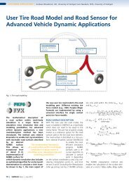
3.2 ASSESSMENT CRITERIA AND<br />
CHARACTERISTIC VALUES<br />
An assessment of the unpleasant vibration<br />
grating subjectively perceived<br />
by the driver’s h<strong>and</strong> on the gear lever<br />
requires objectifi cation of this process<br />
according to measured values. Measured<br />
directly at the gear lever, the interface<br />
to the driver, the gearshift effort<br />
profi le, Figure 4, is a particularly<br />
suitable evaluation variable. The driver<br />
regards a renewed increase in effort<br />
after synchronisation as being very unpleasant<br />
as he does not instinctively<br />
anticipate any further resistance. This<br />
gives rise to the relationship between<br />
maximum synchronising force (Fmax,II)<br />
<strong>and</strong> the double bump (Fmax,VI), Figure<br />
3, as an evaluation variable. The<br />
smaller the ratio Fmax,VI/ Fmax,II, the<br />
more inconspicuous the double bump.<br />
The time dimension of the fault is expressed<br />
by integral IH for the manual<br />
force from the time at which meshing<br />
begins through to the time of positive<br />
engagement, Figure 4. The more<br />
time required for this operation <strong>and</strong><br />
the higher the force amplitudes, the<br />
less easy the gearshift operation as<br />
3 » CUSTOMER APPLICATION<br />
perceived by the driver. The number of<br />
force amplitudes n during the meshing<br />
operation must also be known in<br />
order to distinguish between grating<br />
<strong>and</strong> faultless gear shifts. n = 1 indicates<br />
a faultless gear shift, whereas n > 1 implies<br />
a grating gear shift, Figure 4.<br />
4 SIMPACK SIMULATION<br />
Based on the results of experimental<br />
(test rigs, in vehicle tests) <strong>and</strong> theoretical<br />
research the necessary modelling<br />
depth <strong>and</strong> the degree of detail was<br />
determined in order to generate an<br />
appropriate simulation model. It was<br />
found out that it is essential to model<br />
the complete drive train system with<br />
all of the relevant system characteristics.<br />
This is the only way to ensure that<br />
the reciprocal effects of the individual<br />
subsystems are considered. The studies<br />
described below do not therefore simply<br />
concentrate on the driver <strong>and</strong> the<br />
infl uence exerted by variables inside<br />
the transmission, but also allow for the<br />
vehicle as a whole.<br />
4.1 SIMPACK MBS MODEL<br />
4.1.1 VEHICLE AS A WHOLE<br />
The modular structure of the vehicle<br />
as a whole essentially comprises the<br />
body <strong>and</strong> its masses, with the transmission,<br />
drive train <strong>and</strong> rear axle carrier<br />
sub models connected to its bearing<br />
points, Figure 6 <strong>and</strong> 8.<br />
4.1.2 GEARBOX MODEL, INTERNAL<br />
AND EXTERNAL SHIFT MECHANISMS<br />
The gearbox model comprises a housing,<br />
which is connected to the body<br />
<strong>and</strong> the engine, the synchroniser <strong>and</strong><br />
one gear. Particular importance was<br />
attached to the model of the synchroniser<br />
(sliding sleeve, synchroniser ring<br />
<strong>and</strong> teeth of the synchroniser hub are<br />
mating components), Figure 7. The<br />
according SIMPACK library functionality<br />
(force element) was developed<br />
by INTEC within a project work. The<br />
synchronising torque built up during<br />
the synchronising phase causes system<br />
excitation <strong>and</strong> it is stored in the model<br />
as a measured function of gearshift<br />
effort <strong>and</strong> differential speed. The sliding<br />
sleeve <strong>and</strong> synchroniser hub, which<br />
Dr. Bencker, M. Nussbaumer, BMW<br />
Group, Prof. B. Schlecht, TU Dresden<br />
Figure 3: Five Phases of the Synchronisation<br />
Sequence<br />
Figure 4: Manual Force Profi le showing<br />
Synchronisation<br />
Figure 5: Contact Situation of Synchronisation<br />
Phase IV
» CUSTOMER APPLICATION<br />
Dr. Bencker, M. Nussbaumer, BMW<br />
Group, Prof. B. Schlecht, TU Dresden<br />
Figure 6: Front View of the MBS<br />
Model<br />
Figure 7: Synchroniser (Sliding Sleve,<br />
Synchroniser Ring <strong>and</strong> Synchroniser<br />
Hub)<br />
Figure 8: Rear View of the MBS Model<br />
make contact with one another during<br />
meshing, are represented by geometric<br />
bodies. The forces exerted when these<br />
bodies meet are therefore described<br />
unambiguously. Furthermore, the fl exible<br />
internal <strong>and</strong> external shift mechanisms<br />
are modelled with the pertinent<br />
bearing points on the body <strong>and</strong> gearbox.<br />
These bearing points constitute a<br />
very important variable determining<br />
gearshift comfort in transmission development<br />
<strong>and</strong> therefore require indepth<br />
examination.<br />
4.1.3 ROTARY DRIVE TRAIN MODEL<br />
The rotary drive train model comprises<br />
fl exible coupling, prop shaft, centre<br />
bearing, differential, output shafts <strong>and</strong><br />
tyres. These components are also modelled<br />
in detail <strong>and</strong> are linked to the<br />
body at the relevant bearing points.<br />
4.1.4 REAR AXLE CARRIER MODEL<br />
The entire kinematics of the suspension<br />
<strong>and</strong> all bearing points are stored<br />
in the rear axle carrier model. This enables<br />
modelling of pitch <strong>and</strong> roll vibration,<br />
as well as the translatory longitudinal<br />
vibration of the rear axle carrier,<br />
which must also be considered when<br />
examining vibration grating.<br />
4.1.5 DRIVER MODEL<br />
Great importance is also attached to<br />
realistic modelling of the driver as his<br />
behaviour essentially determines the<br />
overall shifting operation, particularly<br />
during the synchronising <strong>and</strong> meshing<br />
phases. A parameterised mass-springdamper<br />
system enables simulation of<br />
all relevant driver types (sporty, average<br />
<strong>and</strong> comfort oriented), which are<br />
represented by different gearshift effort<br />
values <strong>and</strong>/or shifting times during<br />
the synchronising phase. The interaction<br />
with the internal <strong>and</strong> external<br />
shift mechanisms <strong>and</strong> the synchroniser<br />
gives rise to the gearshift effort profi<br />
le. A constant effort value is specifi ed<br />
for the driver model during the meshing<br />
phase, in which the driver perceives<br />
the response of the drive train<br />
at the gear lever. The interaction with<br />
the vehicle gives rise to a corresponding<br />
double bump or grating.<br />
SIMPACK»News, July 2005<br />
4<br />
4.2 MODEL VERIFICATION<br />
The model is verifi ed according to variables<br />
measured in preliminary tests,<br />
i.e. the torque at the prop shaft, the<br />
rpm of the sliding sleeve, the rpm of<br />
the gear wheel <strong>and</strong> the manual force<br />
profi le. Apart from this, the model is<br />
calibrated with vibration measurements<br />
for the rear axle carrier <strong>and</strong> the<br />
differential. Figure 10 <strong>and</strong> 11 shows<br />
an example of a comparison between<br />
simulated <strong>and</strong> measured synchronising<br />
operations <strong>and</strong> unobstructed drive<br />
train vibration.<br />
5 MODEL ANALYSES<br />
With defi ned boundary conditions,<br />
parameter variations or statistical experimental<br />
design were performed<br />
with the according SIMPACK model.<br />
Conclusions regarding the sensitivity<br />
of components could be reached<br />
quickly <strong>and</strong> easily in order to enable<br />
defi nition of optimum design in a<br />
subsequent stage. Goal confl icts with<br />
other phenomena must be considered<br />
in this respect, however. These include<br />
longitudinal dynamics, stress reversal<br />
behaviour (bucking) <strong>and</strong> acoustics<br />
(clacking, knocking noises during load<br />
reversal).<br />
5.1 BOUNDARY CONDITIONS<br />
<strong>Gearshift</strong> effort is varied within certain<br />
limits during each simulation run,<br />
which comprises numerous individual<br />
computations, to ensure that the simulation<br />
allows for the gear changing<br />
behaviour of both sporty <strong>and</strong> comfortoriented<br />
drivers. The forces taken as<br />
the basis for this are obtained from<br />
in-vehicles measurements <strong>and</strong> they<br />
represent the entire driver spectrum<br />
to be expected from customers. Apart<br />
from this, it is essential to ensure that<br />
the meshing conditions between the<br />
teeth of the sliding sleeve <strong>and</strong> the<br />
synchroniser hub are defi ned when<br />
they make contact for the fi rst time to<br />
enable a comparison of the variants.<br />
The starting conditions are therefore<br />
varied within the tooth pitch in the<br />
model. This method offers a means<br />
of examining a situation in which the<br />
teeth of the sliding sleeve fi t directly
into the gap between the teeth of the<br />
synchroniser hub or the bevels on the<br />
teeth collide with one another. Vehicle<br />
speed is another important variable to<br />
ensure comparability. This is also varied<br />
within certain limits during a simulation<br />
run.<br />
5.2 OPTIMISATION VARIABLES<br />
There are interface variables between<br />
the driver, internal <strong>and</strong> external shift<br />
mechanisms, gearbox, synchroniser<br />
<strong>and</strong> rear drive train subsystems. Optimisation<br />
of the interface variables<br />
between gearbox <strong>and</strong> drive train (reducing<br />
differential speed <strong>and</strong> torque<br />
for meshing, maximum possible axial<br />
force) also brings about a reduction<br />
in the axial force acting on the sliding<br />
sleeve. This must be applied by the<br />
driver via the internal <strong>and</strong> external<br />
shift mechanisms or is transferred to<br />
the driver‘s h<strong>and</strong> <strong>and</strong> is expressed in<br />
the gearshift effort profi le. Optimisation<br />
of the aforementioned variables<br />
therefore also results in an improvement<br />
in the characteristic values for<br />
gearshift comfort.<br />
5.3 PARAMETER VARIATION<br />
Statistical Experimental Design <strong>and</strong><br />
Optimisation by systematically varying<br />
parameters (statistical experimental<br />
design) related to the gearbox, drive<br />
train <strong>and</strong> internal <strong>and</strong> external shift<br />
mechanisms, it is possible to calculate<br />
different variants <strong>and</strong> defi ne one or<br />
more optimised designs on the basis<br />
of the results. As the infl uence exerted<br />
by the various components depends<br />
on the vehicle confi guration to a great<br />
extent, <strong>and</strong> the evaluation criteria<br />
(gearshift comfort, longitudinal dynamics,<br />
stress reversal behaviour) are<br />
determined by the design philosophy,<br />
no general conclusions can or should<br />
be given here.<br />
6 SUMMARY<br />
In an effort to counteract increasing<br />
pressure on costs <strong>and</strong> shorter development<br />
periods, the complete SIMPACK<br />
vehicle model presented in this article<br />
provides a tool that offers a means of<br />
comprehensively studying <strong>and</strong> analys-<br />
5 » CUSTOMER APPLICATION<br />
ing all of the variables which affect<br />
vibration grating. This enables determination<br />
of the sensitivity of each infl<br />
uential parameter <strong>and</strong> identifi cation<br />
of the contrary or reinforcing effects of<br />
a variation. To this end, a preliminary<br />
theoretical <strong>and</strong> experimental system<br />
analysis was carried out to identify the<br />
parameters which infl uence vibration<br />
grating <strong>and</strong> are found in the gearbox,<br />
the internal <strong>and</strong> external shift mechanisms<br />
<strong>and</strong> the rear drive train (including<br />
the rear axle bearing arrangement<br />
<strong>and</strong> rear axle kinematics). Based on<br />
the knowledge acquired with respect<br />
to sequences, processes, sensitivity <strong>and</strong><br />
system behaviour, the SIMPACK simulation<br />
model was produced which is<br />
capable of realistically simulating the<br />
aforementioned vibration phenomenon.<br />
The defi ned characteristic values<br />
can be used to capture the driver’s subjective<br />
sense of comfort when changing<br />
gear in objective measurements,<br />
thereby describing vibration grating.<br />
These variables offer a means of analysing<br />
<strong>and</strong> evaluating in vehicle measurements<br />
<strong>and</strong> simulation results. Based<br />
on the acquired knowledge, various<br />
drive train variants can now be tested<br />
cost-effectively <strong>and</strong> quickly according<br />
to vehicle model <strong>and</strong> associated customer<br />
requirements (sporty or comfort-oriented),<br />
allowing for reciprocal<br />
effects <strong>and</strong> goal confl icts, beginning<br />
at the concept phase <strong>and</strong> going right<br />
through to SOP. One result of this is a<br />
reduction in iterative loops, particularly<br />
with respect to testing <strong>and</strong> trials, as<br />
only the promising variants need to be<br />
tested. Using statistical experimental<br />
design, the test engineer of the future<br />
will be able to perform virtual optimisation<br />
<strong>and</strong> tuning calculations <strong>and</strong> use<br />
these as the basis for defi nition of test<br />
variants.<br />
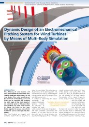
Dr. Bencker, M. Nussbaumer, BMW<br />
Group, Prof. B. Schlecht, TU Dresden<br />
Figure 9: Complete Vehicle Dynamics<br />
System<br />
Figure 10: Measured Synchronisation<br />
Process<br />
Figure 11: Simulated Synchronisation<br />
Process