Two-line Systems - Lincoln Industrial
Two-line Systems - Lincoln Industrial
Two-line Systems - Lincoln Industrial

You also want an ePaper? Increase the reach of your titles
YUMPU automatically turns print PDFs into web optimized ePapers that Google loves.
<strong>Two</strong>-<strong>line</strong> <strong>Systems</strong><br />
Product Catalogue 2008<br />
Productivity is key in<br />
today’s global economy.<br />
Proper lubrication<br />
increases uptime and<br />
makes maintenance<br />
routines simple.
<strong>Two</strong>-<strong>line</strong> <strong>Systems</strong><br />
Our Experience<br />
<strong>Lincoln</strong> was established in 1910<br />
and is the long-standing world<br />
leader in grease lubrication systems<br />
and equipment. Decades<br />
of business experience have<br />
provided us with a high level of<br />
expertise and know-how within<br />
the lubrication system industry.<br />
As a pioneer in the industry, we<br />
will continue being a trendsetter<br />
confidently providing our customers<br />
with the best lubrication system<br />
solutions in both price and quality.<br />
Our Product<br />
<strong>Lincoln</strong> lubrication systems<br />
reduce friction and wear; thereby,<br />
decreasing maintenance costs,<br />
improving productivity, ensuring<br />
a higher level of safety and<br />
contribution to the environment.<br />
2<br />
Our Service<br />
Our customer service includes<br />
the consulting, engineering and<br />
planning of customer-oriented<br />
systems for all applications,<br />
the manufacturing of standard<br />
components such as pumps,<br />
metering devices or control<br />
equipment, the installation and<br />
start up of lubrication systems<br />
on site in all parts of the world,<br />
as well as the customer training,<br />
and after-market service.<br />
Our Quality<br />
Our certified Quality Management<br />
System according to DIN EN ISO<br />
9001, our expertise, consulting<br />
qualities and inventiveness, lead<br />
the way for future customer-oriented,<br />
economical and intelligent<br />
solutions.<br />
Our Environmental<br />
Management System<br />
Our Environmental Management<br />
System according to DIN EN ISO<br />
14001 and EMAS, is an integral<br />
part of our company philosophy<br />
that reflects <strong>Lincoln</strong>’s future<br />
orientation.<br />
Our Motto<br />
Keep in motion –<br />
Bleiben Sie mit uns in Bewegung!
Table of Contents<br />
<strong>Two</strong>-<strong>line</strong> <strong>Systems</strong><br />
Schematic <strong>Two</strong>-<strong>line</strong> <strong>Systems</strong> 4 - 5<br />
Schematic<br />
Pumps 6 - 12<br />
HJ2, ZPU, ZPU Accessories<br />
<strong>Two</strong>-<strong>line</strong> Metering Devices 13 - 19<br />
VSG, VSL, VSKH, VSKV<br />
Change-over Valves 20 - 23<br />
DU1, MP-2, EM-U2<br />
End-of-<strong>line</strong> Pressure Units 24<br />
Index 25 - 27 <strong>Two</strong>-<strong>line</strong> <strong>Systems</strong><br />
Part Number Page<br />
223-13052-1 6/19<br />
223-13052-2 6/19<br />
223-13052-3 6/19<br />
303-17505-1 19<br />
303-17506-1 19<br />
303-17507-1 19<br />
3
<strong>Two</strong>-<strong>line</strong> <strong>Systems</strong><br />
Application<br />
● Large systems with<br />
dispersed lube points<br />
● Varying lubrication quantities<br />
● Ideal for rigorous conditions<br />
(e.g. coldness)<br />
Sample applications:<br />
Large systems using grease<br />
up to NLGI 2<br />
Industries<br />
Cement plants, steel mills, power<br />
plants, mining, large machines<br />
The advantage of a two-<strong>line</strong><br />
system is that it supplies an<br />
exact metered quantity of lubricant<br />
from one pumpstation over large<br />
distances.<br />
The metering devices are operated<br />
by two main <strong>line</strong>s, whereby here<br />
the lubricant is simultaneously<br />
the control medium of the system.<br />
The two-<strong>line</strong> system can be combined<br />
with secondary progressive<br />
metering devices, thereby increasing<br />
the total number of lubrication<br />
points that are served by a two<strong>line</strong><br />
metering device.<br />
Capabilities<br />
● <strong>Lincoln</strong>‘s high pressure<br />
capability allows small<br />
diameter tubing to be used,<br />
thereby reducing installation<br />
and material costs.<br />
Additionally, this reduces the<br />
amount of grease in the tubing<br />
which over a long period of<br />
time may deteriorate.<br />
● Visual or electric monitoring<br />
of each metering device<br />
outlet pair.<br />
● If a bearing clogs or a metering<br />
device outlet fails to function, all<br />
other outlet pairs will continue<br />
to function normally.<br />
● Simple and individual<br />
metering of lubricant.<br />
4<br />
● Problem-free readjustment<br />
of metered lubricant<br />
output after installation.<br />
● Optimum monitoring<br />
and control possibility<br />
with a field bus system.<br />
● Easy to extend.<br />
The Self-thinking System<br />
The special components of a<br />
<strong>Lincoln</strong> self-thinking two-<strong>line</strong><br />
system adjust the system to the<br />
optimum required pressure.<br />
Conventional two-<strong>line</strong> systems<br />
operate on a fixed pressure<br />
difference principle. This means<br />
that the change-over process<br />
is then initialized when a fixed<br />
pressure at the end of the <strong>line</strong>s<br />
has been reached.<br />
1<br />
Schematic <strong>Two</strong>-<strong>line</strong> System<br />
Consequently, the system always<br />
operates at a maximum pressure.<br />
With the <strong>Lincoln</strong> self-thinking<br />
two-<strong>line</strong> system, the pressure is<br />
constantly monitored and modified<br />
accordingly. The system<br />
thereby automatically regulates<br />
the pressure and can compensate<br />
for temperature fluctuations.<br />
Manual adjustments of the<br />
system, even during installation,<br />
are no longer required.<br />
Since only the effective required<br />
pressure is generated during<br />
each lubrication cycle, the pump<br />
and other system components<br />
have a longer service life, the<br />
system always operates in its<br />
2<br />
3
A<br />
B<br />
A further advantage is the direct<br />
display of all important parameters<br />
on the controller.<br />
This enables full monitoring of<br />
the system and the pump.<br />
Function of a <strong>Two</strong>-Line System<br />
In the first half-cycle, the lubricant<br />
is pumped into the main <strong>line</strong> (A)<br />
and the main <strong>line</strong> (B) is connected<br />
to the relief <strong>line</strong>. The lubricant,<br />
which is also the control medium<br />
for the system, is supplied to the<br />
metering devices. The pistons of<br />
the metering devices are moved<br />
into their adjusted end positions,<br />
thus dispensing an exact metered<br />
quantity of grease. Once all<br />
metering devices have dispensed<br />
their lubricant to the consumption<br />
point, the system is hydraulically<br />
4<br />
closed which causes the pressure<br />
in main <strong>line</strong> (A) to rise, and is<br />
measured by the pressure transducer.<br />
The control unit turns the<br />
pump off and signals the changeover<br />
valve to relieve main <strong>line</strong> (A).<br />
Schematic <strong>Two</strong>-<strong>line</strong> System<br />
At this point half of the lubrication<br />
points in the system have been<br />
lubricated. In the second halfcycle,<br />
main <strong>line</strong> (B) is pressurized<br />
and the cycle continues as before.<br />
Common Components<br />
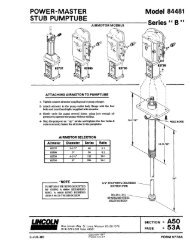
pumps HJ2 manual pumps, ZPU01/02, ZPU08/14/24<br />
with reservoir: electric pumps<br />
for drums: PowerMaster pneumatic pumps*,<br />
Lubrigun pneumatic pumps<br />
metering devices: VSG, VSL, VSKH, VSKV<br />
change-over valves: DU1 pressure change-over valve<br />
EM-U2 electric change-over valve<br />
MP2 pneumatic change-over valve<br />
MHY1 hydraulic change-over valve<br />
*Not covered in this catalogue – ask your <strong>Lincoln</strong> representative for details.<br />
Legende<br />
1 Pump<br />
2 Change-over valve<br />
3 Metering devices<br />
4 Pressure trancducer<br />
A , B Main <strong>line</strong><br />
A<br />
B<br />
5
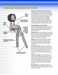
HJ2 Pumps<br />
HJ2 Pump<br />
Technical Data<br />
6<br />
The central lubrication pump type HJ (Helios Junior) is a manually<br />
operated high-pressure pump used for the supply of grease or oil in<br />
progressive systems, or when equipped with one pressure <strong>line</strong> and one<br />
relief <strong>line</strong>, for small two-<strong>line</strong> lubrication systems.<br />
Part No. Description<br />
603-40558-3 HJ2L-30 left-hand lever 1 outlet<br />
603-40558-4 HJ2R-30 right-hand lever 1 outlet<br />
603-40558-1 HJ2AL-30 left-hand lever 2 outlets*<br />
603-40558-2 HJ2AR-30 right-hand lever 2 outlets*<br />
*for progressive systems<br />
HJ2 HJ2A<br />
number of outlets 1 2<br />
lubricant output<br />
per lever movement 2 cm 3 (0.122 in 3 ) 2x1 cm 3 (2 X 0.061 in 3 )<br />
operating pressure 300 bars (4350psi)<br />
hand force at maximum pressure 300 N<br />
suitable lubricants grease up to NGLI 3<br />
outlet threaded connection G 1/4 female (BSPP)<br />
reservoir capacity 3 liters (183 in 3 )<br />
weight empty 8.7 kg (19 lbs) 8.9 kg (19.6) lbs<br />
dimensions (L x W x H) 410 x 140 x 393 mm (16.1 x 5.5 x 15.5 in)<br />
Accessories<br />
Part No. Description<br />
223-13052-1 check valve for 6 mm tube<br />
223-13052-2 check valve for 8 mm tube<br />
223-13052-3 check valve for 10 mm tube
ZPU01/02 Pumps<br />
Depending on the number of pump elements, these high-pressure,<br />
high-volume pumps can be used for following applications:<br />
1.As a supply pump for small to midsize two-<strong>line</strong> systems<br />
(‘F’ version with filter block, safety valve and pressure gauge) in<br />
conjunction with a pressure-controlled change-over valve. The supply<br />
range lies within a radius of approximately 50 m from the pump<br />
depending on the ambient temperature and type of lubricant.<br />
2.As a supply pump for progressive and single-<strong>line</strong> systems<br />
(‘F’ or ‘V’ version).<br />
The principle of operation is similar to the very reliable and efficient<br />
multi-<strong>line</strong> pump 215.They are available with or without an ultrasonic<br />
level control and come with a 3-phase multi-range motor for<br />
380 – 420 volt at 50 Hz or 440 – 480 volt at 60 Hz or with a free shaft<br />
end for use with other motors. Gear ratio is 100:1.<br />
ZPU02 ... F<br />
Popular Models<br />
Part No. Description Motor Reservoir Size Level Pump<br />
Liters In 3 Lbs. Control Element<br />
661-40692-3 ZPU02-M100- 3-phase 10 610 20 yes bracket with<br />
010XYBU-F-380- 2 elements, filter block,<br />
420/440-480 pressure gauge<br />
661-40710-3 ZPU02-M100- 3-phase 30 1830 60 yes and safety valve<br />
030XYBU-F-380-<br />
420/440-480<br />
661-40644-7 ZPU02-M100- none 10 610 20 no<br />
010XN-F-000<br />
661-40710-7 ZPU01-M100- 3-phase 10 610 20 yes 1 element only<br />
010-XYBU-E-380-<br />
420/440-480<br />
Technical Data<br />
Number of Elements 1 or 2<br />
threaded connection:<br />
E version G 1/4 female (BSPP)<br />
V or F versions for 10 mm tube or G 3/8 female (BSPP)<br />
filling connection G 3/8 female (BSPP)<br />
maximum operating pressure 300 bars 4350 psi<br />
"E” version must be protected with pressure relief valve (not included)<br />
suitable lubricant grease up to NGLI 2 / NLGI 3 on request<br />
oil with a viscosity of min. 20 cSt<br />
lubricant output per pump element<br />
(output increases by 20%<br />
for 60 Hz applications) 800 cm 3 / hour (49 in 3 / hour)<br />
reservoir sizes 10 or 30 liter (2.6 or 8 U.S. gal)<br />
temperature range -20° to 70° C (-4° to 158° F)<br />
7
ZPU01/02 Pumps<br />
Required Pressure Relief Valve for Single Element ”E“ Version<br />
Part No. Description Tube Diameter Pressure<br />
624-25478-1 relief valve 6 mm tube 200 bars (2900 psi)<br />
624-25479-1 relief valve 6 mm tube 350 bars (5076 psi)<br />
624-25480-1 relief valve 8 mm tube 200 bars (2900 psi)<br />
624-25481-1 relief valve 8 mm tube 350 bars (5076 psi)<br />
624-25482-1 relief valve 10 mm tube 200 bars (2900 psi)<br />
624-28483-1 relief valve 10 mm tube 350 bars (5076 psi)<br />
Dimensions<br />
Reservoir Size Height Width Depth<br />
10 liters (without<br />
low-level control) 514 mm (20.25 in) 379 mm (15 in) 317 mm (12.5 in)<br />
30 liters (without<br />
low-level control) 754 mm (29.75 in) 431 mm (17 in) 377 mm (15 in)<br />
low-level<br />
sensor 30 mm (1.2 in) 125 mm (5 in) 65 mm (2.75 in)<br />
8
Identification Code<br />
Models ZPU01/02<br />
Description<br />
Type Identification Code<br />
Examples: ZPU02 M 100 030 XYBU F 380-420/440-480<br />
Basic Type of Central Lubrication Pump:<br />
ZPU01 : pump with 1 element<br />
ZPU02 : pump with 2 elements<br />
Drive Assemblies:<br />
M : three-phase flanged motor<br />
motor designation with extension, e.g.<br />
for voltages frequencies, explosionproof<br />
design is added to the pump<br />
type code.<br />
100 : gear ratio = 1 : 100<br />
Reservoir Assemblies:<br />
010 : reservoir capacity 10 l<br />
030 : reservoir capacity 30 l<br />
XY : reservoir for grease and oil<br />
N : reservoir without level monitoring<br />
BU : reservoir with low and high-level control<br />
(ultrasonic sensor)<br />
Note: The ultrasonic sensor is equipped with 2 switching points. If only one<br />
low-level control is desired, the corresponding contacts must be connected.<br />
A 24VDC supply voltage is required for the sensor.<br />
Pump Elements:<br />
E : element(s)<br />
V : bracket with element(s) and pressure gauge<br />
F : bracket with element(s), filter block,<br />
pressure gauge and safety valve<br />
Extension for Motor Designation:<br />
380-420/440-480 : standard multi-range motor for 380-420V/50 Hz<br />
and 440-480 V/60 Hz<br />
000 : pump without motor, however with connecting flange<br />
9
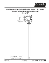
ZPU08/14/24 Pumps<br />
The high-pressure ZPU08, ZPU14<br />
and ZPU24 pumps are primarily<br />
used in two-<strong>line</strong> systems or as a<br />
supply pump.<br />
The pump element, made of hardened<br />
steel, operates as a piston<br />
pump with two pistons operating<br />
in opposite directions which draw<br />
in lubricant alternately and feed it<br />
through the outlet hole to the<br />
10<br />
pressure <strong>line</strong>. The outlet channels<br />
of the high-pressure pistons are<br />
controlled by a floating piston.<br />
These state-of-the-art pumps are<br />
extremely serviceable and reliable.<br />
All main components are easily<br />
accessible. The pumps come<br />
standard with a pressure relief<br />
valve, a check valve, a lubricant<br />
filter, and a pressure gauge.<br />
Popular Models<br />
Part No. Description Reservoir Size Level Motor<br />
Liters In3 ZPU08-40XL<br />
Lbs. Control<br />
605-40272-5 ZPU08G-40XL-380-415,<br />
420-480<br />
40 2441 80 yes 3-phase<br />
605-40273-3 ZPU08G-100XB-380-415,<br />
420-80<br />
100 6102 200 yes 3-phase<br />
605-40276-3 ZPU14G-100XB-380-415,<br />
420-480<br />
100 6102 200 yes 3-phase<br />
605-40279-3 ZPU24G-100XB-380-415,<br />
420-480<br />
100 6102 200 yes 3-phase<br />
Technical Data<br />
Model ZPU08 ZPU14 ZPU24<br />
lubricant output (output increases by 20% 8 liters/hour 14 liters/hour 24 liters/hour<br />
for 60 Hz applications) (2.1 U.S. gal/h) (3.7 U.S. gal/h) (6.3 U.S. gal/h)<br />
488 in3 /h 854 in3 /h 1464 in3 /h<br />
drive speed 60 rpm 100 rpm 180 rpm<br />
operating pressure 400 bars (5800 psi)<br />
connection thread pressure <strong>line</strong> G 3/4 female (BSPP)<br />
relief <strong>line</strong> G 3/4 female (BSPP)<br />
filling <strong>line</strong> G 3/4 female (BSPP)<br />
direction of rotation of the drive optional<br />
reservoir capacity 40 or 100 liters/(10 or 26 U.S. gal)<br />
2441 in3 or 6102 in3 lubricant filter filter area 5.1 cm2 grade of filtration 280 µm<br />
overpressure valve fixed setting to 410 bars (5946 psi) tamper-proof<br />
operating temperature -20° to 80 °C (-4° to 176 °F)<br />
Dimensions<br />
Reservoir Size Height Width Depth<br />
40 liters 760 mm (30 in) 670 –735 mm (26–29 in) 410 mm (16 in)<br />
(without low-level control) depending on version<br />
100 liters 975 mm (38.5 in) 760–825 mm (30–32.5 in) 500 mm (20 in)<br />
(without low-level control) depending on version
ZPU Pump Accessories<br />
623-25461-2<br />
Accessories<br />
Part No. Description<br />
623-25456-2 electric pressure switch 75 – 170 bars (1087 – 2465 psi)<br />
623-25461-2 electric pressure switch 160 – 400 bars (2320 – 5800 psi)<br />
623-37243-1 electric pressure switch kit for 40 l reservoir versions<br />
(includes part number 623-25461-2 and required connection fittings)<br />
623-37242-1 electric pressure switch kit for 100 l reservoir versions<br />
(includes part number 623-25461-2 and required connection fittings)<br />
623-37567-1 electronic pressure transducer kit for 40 and 100 l reservoir versions<br />
(includes electronic pressure switch with digital display, part number 234-13194-4,<br />
see accessories)<br />
Electronic Pressure Transducer Kit<br />
623-37567-1<br />
623-37243-1<br />
11
Identification Code<br />
Pump Models ZPU08,<br />
ZPU14 & ZPU24<br />
Model Designation<br />
The complete pump unit is defined by a model<br />
designation (mentioned on the nameplate).<br />
Examples of model designations: ZPU08 F 40 XL 000<br />
ZPU08 G 40 XYBU 380-415/420-480 C<br />
Lubricant Output:<br />
08 = 8 dm 3<br />
14 = 14 dm 3<br />
24 = 24 dm 3<br />
12<br />
h -1<br />
h -1<br />
h -1<br />
Type of Drive:<br />
F : with free shaft end<br />
G : with flanged gear motor<br />
construction IMB5<br />
S : with worm gear and 3-phase<br />
motor construction IMV1<br />
SF : with worm gear and shaft<br />
end, suitable for 3-phase<br />
motor construction<br />
S and SF only available for model 08<br />
Reservoir Capacity:<br />
40 = 40 dm 2<br />
100 = 100 dm 2<br />
Reservoir Design:<br />
XN = grease reservoir, standard design<br />
XV = grease reservoir with high-level control<br />
XVD = grease with high-level control and<br />
cover interlock switch<br />
XL = grease reservoir with low-level control<br />
XB = grease reservoir with high and low-level control<br />
XYBU = reservoir for grease or oil with low-level control<br />
via ultrasonic sensor<br />
Supply Voltage of the Motors:<br />
380-415/420-480 = standard multi-range motor for<br />
380-415/420-480V 50 Hz and 420-480V 60 Hz<br />
500 = 500V, 50 Hz<br />
000 = unit without motor<br />
other voltages on request<br />
C = version as feed pump for COBRA<br />
ZPU14 G 100 XB 500<br />
ZPU14 S 40 XYBU 380-415/420-480
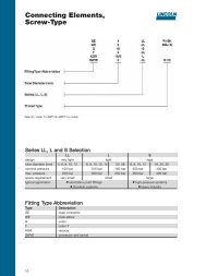
VSG, VSL, VSKH and VSKV<br />
<strong>Two</strong>-<strong>line</strong> Metering Devices<br />
VSG-KR<br />
These high quality, galvanized<br />
steel metering devices are<br />
designed for high-pressure (up<br />
to 400 bar) two-<strong>line</strong> systems.<br />
They can also be used in low to<br />
medium-pressure systems. They<br />
are available with up to 8 outlets.<br />
Each outlet pair is equipped<br />
with an indicator pin for visual<br />
monitoring. Additional optional<br />
features include rust proof<br />
material, rust and acid proof<br />
material, electrical monitoring,<br />
adjusting device with magnetically<br />
operated function for rigorous<br />
environments, viton seals for high<br />
temperature applications, and NPT<br />
inlet/outlet threads. Refer<br />
to the identification code for model<br />
designations to order these devices<br />
with the additional features.<br />
All models function on the same<br />
principle. The difference between<br />
VSL, VSG and VSKH lies in the<br />
output per outlet. Model VSKV has<br />
the same features as the VSKH<br />
with the exception that the outlet<br />
ports are located on the front face<br />
(vertical positioning). This provides<br />
an alternative for applications requiring<br />
a different tube orientation.<br />
Versions ... MD (with magnetically<br />
operated indication of function) are<br />
designed without dynamic seals and<br />
can work under extremely adverse<br />
ambient conditions: water, dust, high<br />
temperature up to 120° C (176° F).<br />
VSG-KR Models<br />
VSG-KR<br />
Indicator Pin and Adjustable Output 0–2.2 cm 3 (0–0.13 in 3 )<br />
Connection Connection Number Connection Thread Connection Thread Connection Thread<br />
Thread Thread of BSPP NPTF NPTF<br />
BSPP BSPP Outlets<br />
Carbon Steel Stainless Steel Stainless Steel Carbon Steel Stainless Steel<br />
Galvanized (VA 1.4305/303) (VA 1.4571/316 Ti) Galvanized (VA 1.4305)<br />
620-40022-1 620-40567-1 1 620-40022-2<br />
620-40015-1 620-40567-2 2 620-40839-2 620-40015-2<br />
620-40022-3 620-40567-3 3 620-40022-4<br />
620-40015-3 620-40567-4 4 620-40839-4 620-40015-4<br />
620-40022-5 620-40567-5 5 620-40022-6<br />
620-40015-5 620-40567-6 6 620-40839-6 620-40015-6<br />
620-40022-7 620-40567-7 7 620-40022-8<br />
620-40015-7 620-40567-8 8 620-40839-8 620-40015-8<br />
13
VSG, VSL, VSKH and VSKV<br />
<strong>Two</strong>-<strong>line</strong> Metering Devices<br />
VSG-KD and D<br />
Indicator Pin and Fixed Output* 2.2 cm 3 (0.13 in 3 ) Metering Screw (KD)<br />
or with Metering Screw only (D) as Shown<br />
KD D KD D<br />
Connection Thread Number Connection Thread<br />
BSPP of Outlets NPTF<br />
Carbon Steel Galvanized Carbon Steel Galvanized<br />
620-40023-1 620-40025-1 1 620-40023-2 620-40025-2<br />
620-40023-3 620-40025-3 2 620-40023-4 620-40025-4<br />
620-40023-5 620-40025-5 3 620-40023-6 620-40025-6<br />
620-40023-7 620-40025-7 4 620-40023-8 620-40025-8<br />
620-40024-1 620-40026-1 5 620-40024-2 620-40026-2<br />
620-40024-3 620-40026-3 6 620-40024-4 620-40026-4<br />
620-40024-5 620-40026-5 7 620-40024-6 620-40026-6<br />
620-40024-7 620-40026-7 8 620-40024-8 620-40026-8<br />
*also available: 0.55, 1.1, 1.65 cm 3<br />
(0.0336, 0.067, 0.1 in 3 )<br />
VSG-KR-NP<br />
Indicator Pin, Proximity Switch for Circular Plug M12 ( 237-13442-4)<br />
and Adjustable Output 0–2.2 cm 3 (0–0.13 in 3 )<br />
Connection Thread Number Connection Thread<br />
BSPP of Outlets NPTF<br />
Carbon Steel Galvanized Carbon Steel Galvanized<br />
620-40733-1 1<br />
620-40733-2 2<br />
620-40733-3 3<br />
620-40733-4 4<br />
620-40733-5 5<br />
620-40733-6 6<br />
620-40733-7 7<br />
620-40733-8 8<br />
Note: High pressure-rated proximity switch is available as a retrofit for<br />
VSG models beyond series 9905. Part Number: 520-34018-1<br />
14<br />
VSG8-D<br />
VSG2KR-NP
MD<br />
Magnetic Indicator Device<br />
The MD magnetic indicator device<br />
is completely maintenance free and<br />
is suitable for extreme ambient<br />
conditions in the heavy industry.<br />
Even at temperatures of up to 120°C<br />
the device is resistant to dust and<br />
steam penetration. Therefore it is<br />
ideal for application in continuous<br />
casters or rolling mills.<br />
In conventional two-<strong>line</strong> metering<br />
devices the indicator pin has been<br />
the weak spot when the metering<br />
device is subjected to full operating<br />
pressure. However, with the magnetic<br />
indicator device, seals are<br />
not required. The movement of the<br />
indicator pin is conveyed without<br />
contact by the aid of a strong magnet<br />
to the outer control ring sleeve.<br />
The control ring is coated with a<br />
bright colour so that it is visible even<br />
in poorly lit conditions.<br />
The output of the two-<strong>line</strong> metering<br />
devices is adjusted by means of<br />
metering screws available in<br />
different sizes.<br />
VSG with magnetic indicator device<br />
Protection cap Adjusting device<br />
Brass Plastic<br />
520-33105-1 520-33270-1 A 0.55 cm 3<br />
520-33106-1 520-33271-1 B 1.10 cm 3<br />
520-33107-1 520-33272-1 C 1.65 cm 3<br />
520-33073-1 520-33273-1 D 2.20 cm 3<br />
VSL with magnetic indicator device<br />
Protection cap Adjusting device<br />
Brass Plastic<br />
520-33103-1 520-33274-1 A 1.25 cm 3<br />
520-33104-1 520-33275-1 B 2.50 cm 3<br />
520-33108-1 520-33276-1 C 3.75 cm 3<br />
520-33074-1 520-33277-1 D 5.00 cm 3<br />
Technische Daten<br />
Operating pressure: max. 400 bars<br />
Operating temperature: max. 120° C<br />
VSKH/VSKV with magnetic indicator device<br />
Protection cap Adjusting device<br />
Brass Plastic<br />
520-33109-1 520-33266-1 A 0.30 cm 3<br />
520-33110-1 520-33267-1 B 0.60 cm 3<br />
520-33112-1 520-33268-1 C 1.20 cm 3<br />
520-33075-1 520-33269-1 D 1.50 cm 3<br />
VSL-MDMS<br />
15
VSG, VSL, VSKH and VSKV<br />
<strong>Two</strong>-<strong>line</strong> Metering Devices<br />
VSG2-KR-KS<br />
VSG2-KR-KA<br />
16<br />
VSG-KR-KS Indicator Pin/Limit Switch<br />
Adjustable Output 0–2.2 cm 3 (0– 0.13 in 3 )<br />
Connection Thread Number Connection Thread<br />
BSPP of Outlets NPTF<br />
Carbon Steel Galvanized Carbon Steel Galvanized<br />
620-40027-1 1 620-40027-2<br />
620-40027-3 2 620-40027-4<br />
620-40027-5 3 620-40027-6<br />
620-40027-7 4 620-40027-8<br />
620-40028-1 5 620-40028-2<br />
620-40028-3 6 620-40028-4<br />
620-40028-5 7 620-40028-6<br />
620-40028-7 8 620-40028-8<br />
VSG-KR-KA Indicator Pin & Adapter for Proximity Switch<br />
(Thread M12 x 1) Adjustable Output 0–2.2 cm 3 (0– 0.13 in 3 )<br />
Connection Thread Number Connection Thread<br />
BSPP of Outlets NPTF<br />
Carbon Steel Galvanized Carbon Steel Galvanized<br />
620-40605-1 2<br />
620-40605-2 4<br />
620-40605-3 6<br />
620-40605-4 8
VSG, VSL, VSKH and VSKV<br />
<strong>Two</strong>-<strong>line</strong> Metering Devices<br />
VSL-KR Indicator Pin and Adjustable Output 0–5 cm 3 (0–0.3 in 3 )<br />
Connection Thread Number Connection Thread<br />
BSPP of Outlets NPTF<br />
Carbon Steel Galvanized Carbon Steel Galvanized<br />
620-40062-1 1 620-40062-2<br />
620-40062-3 2 620-40062-4<br />
620-40062-5 3 620-40062-6<br />
620-40062-7 4 620-40062-8<br />
620-40064-1 5 610-40064-2<br />
620-40064-3 6 620-40064-4<br />
620-40064-5 7 620-40064-6<br />
620-40064-7 8 620-40064-8<br />
VSL-KD & D<br />
Indicator Pin and Fixed Output* 5.0 cm 3 (0.3 in 3 ) Metering Screw (KD)<br />
or with Metering Screw only (D) as Shown<br />
VSL4-KR<br />
VSL8-D<br />
KD D KD D<br />
Connection Thread Number Connection Thread<br />
BSPP of Outlets NPTF<br />
Carbon Steel Galvanized Carbon Steel Galvanized<br />
620-40065-1 620-40063-1 1 620-40065-2 620-40063-2<br />
620-40065-3 620-40063-3 2 620-40065-4 620-40063-4<br />
620-40065-5 620-40063-5 3 620-40065-6 620-40063-6<br />
620-40065-7 620-40063-7 4 620-40065-6 620-40063-8<br />
620-40066-1 620-40067-1 5 620-40066-2 620-40067-2<br />
620-40066-3 620-40067-3 6 620-40066-4 620-40067-4<br />
620-40066-5 620-40067-5 7 620-40066-6 620-40067-6<br />
620-40066-7 620-40067-7 8 620-40066-8 620-40067-8<br />
*also available: 1.25, 2.5, 3.75 cm 3<br />
(0.07, 0.15, 0.228 in 3 )<br />
VSL-KR-KA Indicator Pin & Adapter for Proximity Switch<br />
(Thread M12 x 1) Adjustable Output 0–5 cm 3 (0–0.3 in 3 )<br />
Connection Thread Number Connection Thread<br />
BSPP of Outlets NPTF<br />
Carbon Steel Galvanized Carbon Steel Galvanized<br />
620-40637-2 2<br />
620-40637-4 4<br />
620-40637-6 6<br />
620-40637-8 8<br />
VSL2-KR-KA<br />
17
VSG, VSL, VSKH and VSKV<br />
<strong>Two</strong>-<strong>line</strong> Metering Devices<br />
VSKV5-KR VSKH5-KR<br />
VSKH-KR and VSKV-KR Indicator Pin & Adjustable Output 0–1.5 cm 3 (0–0.09 in 3 )<br />
VSKH (Horizontal) Number VSKV (Vertical)<br />
Connection Thread BSPP of Outlets Connection Thread BSPP<br />
Carbon Steel 303 Stainless 316Ti Stainless Carbon Steel 303 Stainless 316Ti Stainless<br />
Galvanized Steel (VA 1.4305) Steel (VA1.4571) Galvanized Steel (VA 1.4305) Steel (VA1.4571)<br />
620-27438-1 620-27488-1 620-27766-1 1 620-27442-1 620-27496-1 620-27857-1<br />
620-27418-1 620-27489-1 620-27767-1 2 620-27422-1 620-27497-1 620-27858-1<br />
620-27439-1 620-27490-1 620-27768-1 3 620-27443-1 620-27498-1 620-27859-1<br />
620-27419-1 620-27491-1 620-27769-1 4 620-27423-1 620-27499-1 620-27860-1<br />
620-27440-1 620-27492-1 620-27770-1 5 620-27444-1 620-27500-1 620-27861-1<br />
620-27420-1 620-27493-1 620-27771-1 6 620-27424-1 620-27501-1 620-27862-1<br />
620-27441-1 620-27494-1 620-27772-1 7 620-27445-1 620-27502-1 620-27863-1<br />
620-27421-1 620-27495-1 620-27773-1 8 620-27425-1 620-27503-1 620-27864-1<br />
Technical Data<br />
Model VSL VSG VSKH VSKV<br />
output per outlet and stroke 0–5.0 cm 3 0–2.2 cm 3 0–1.5 cm 3 0–1.5 cm 3<br />
(KR versions) (0–0.3 in 3 ) (0–0.13 in 3 ) (0–0.09 in 3 ) (0–0.09 in 3 )<br />
inlet thread G3/8 (BSPP) G3/8 (BSPP) G1/4 (BSPP) G1/4 (BSPP)<br />
3/8 NPTF 3/8 NPTF 1/4 NPTF 1/4 NPTF<br />
outlet thread G1/4 (BSPP) G1/4 (BSPP) G1/4 (BSPP) G1/4 (BSPP)<br />
1/4 NPTF 1/4 NPTF 1/4 NPTF 1/4 NPTF<br />
maximum operating pressure 400 bars (5800 psi)<br />
materials available carbon steel galvanized<br />
stainless steel: 1.4305 / 303<br />
stainless steel:<br />
14571 / 316 Ti<br />
maximum operating 120° C (248° F) for MR and viton versions (KRFKM)<br />
temperature 80° C (176° F) for standard versions (KR)<br />
Dimensions for Standard KR Versions<br />
Model Height Width Depth<br />
VSG-KR 122 mm (4.86 in) 2 outlet: 44.5 mm (1.78 in) 54 mm (2.16 in)<br />
4 outlet: 76 mm (3.04 in)<br />
VSL-KR 140 mm (5.6 in) 6 outlet: 108 mm (4.32 in)<br />
8 outlet: 140 mm (5.6 in)<br />
VSKH-KR 124 mm (4.96 in) 2 outlet: 52 mm (2.08 in) 57 mm (2.28 in)<br />
VSKV-KR 4 outlet : 80 mm (3.2 in)<br />
6 outlet: 108 mm (4.32 in)<br />
8 outlet: 136 mm (5.44 in)<br />
18
Identification Code<br />
VSG, VSL, VSKH and VSKV<br />
<strong>Two</strong>-<strong>line</strong> Metering Devices<br />
Basic Types:<br />
VSKV = outlet vertical<br />
VSKH = outlet horizontal<br />
VSG/VSL = outlet horizontal<br />
Number of Outlets (max. 8):<br />
Standard Version<br />
Steel Body Galvanized:<br />
VA = stainless steel body<br />
Adjustment Device & Monitoring:<br />
KR = with indicator pin and infinitely<br />
variable adjustment device<br />
KRFKM = with indicator and infinitely variable<br />
adjustment device with viton seals<br />
(max. operating temp. 120 ∞C / 248 ∞F)<br />
MDMS = magnetic indicator and infinitely<br />
variable adjustment device<br />
KD = with indicator pin and metering screw<br />
D = with metering screw<br />
0.1; 0.3; 0.6; 0.9; 1.2; 1.5 cm 3<br />
Adjustment Device Standard Version Galvanized:<br />
NP = piston detector<br />
KN = indicator pin and proximity switch<br />
KS = indicator pin and limit switch<br />
KA = indicator pin and adapter<br />
(proximity switch to be supplied by customer)<br />
BA = internal abbreviations<br />
TU = internal abbreviations<br />
H = internal abbreviations<br />
C = internal abbreviations<br />
01, 02, 03 = two-digit number for special versions<br />
A = US-version (NPT - thread)<br />
Stainless Steel (Except VSL Models)<br />
Material Number:<br />
1.4305<br />
1.4571 (acid resistant) for VSKH/VSKV/VSG only<br />
VSKV 6 VA -KR FKM -KN -01 (1.4571)<br />
VSKV 2 VA -KR (1.4305)<br />
VSG 4 -KR -NP<br />
VSKV 5 -KR -KS C<br />
VSKV 8 -KR -KN TU -A<br />
VSKH 4 VA -KS H (1.4305)<br />
VSKV 4 -D 0,6 -KS H<br />
VSKH 2 -KR (1.4305)<br />
19
VSG, VSL, VSKH and VSKV<br />
<strong>Two</strong>-<strong>line</strong> Metering Devices<br />
Accessories<br />
Part No. Description<br />
303-17526-2 closure plug for VSG/VSL<br />
420-22139-1 outlet extension VSG (R1/4 x R1/4)<br />
420-22140-1 outlet extension VSL (R1/4 x R1/4)<br />
420-23628-1 outlet extension VSKH (R1/4 x R1/4)<br />
420-23790-1 outlet extension VSKH (R1/4 x R1/4) stainless steel<br />
303-17505-1 metering screw VSG 0.55 cm3 (0.021 in3 )<br />
303-17506-1 metering screw VSG 1.10 cm3 (0.043 in3 )<br />
303-17507-1 metering screw VSG 1.65 cm3 (0.065 in3 )<br />
303-17508-1 metering screw VSG 2.2 cm3 (0.087 in3 )<br />
303-17509-1 metering screw VSL 1.25 cm3 (0.05 in3 )<br />
303-17510-1 metering screw VSL 2.50 cm3 (0.099 in3 )<br />
303-17511-1 metering screw VSL 3.75 cm3 (0.15 in3 )<br />
303-17512-1 metering screw VSL 5.00 cm3 (0.196 in3 )<br />
223-13052-1 outlet check valve for 6 mm tube*<br />
223-13052-2 outlet check valve for 8 mm tube*<br />
223-13052-3 outlet check valve for 10 mm tube*<br />
421-21288-1 mounting spacer ring 8.5 x 18 x 5<br />
* Outlet check valves are recommended when secondary progressive metering devices are used, or when<br />
the compression volume of the grease (about 2%) in the feed <strong>line</strong> to the lubrication point exceeds the ou<br />
put per outlet.<br />
Welding mounting plates are available for all metering devices – ask your <strong>Lincoln</strong> representative for details.<br />
20
Change-over Valves DU1<br />
DU1-GKS<br />
<strong>Lincoln</strong> change-over valves<br />
come in pressure controlled,<br />
pneumatically operated, electric<br />
motor operated or hydraulically<br />
operated versions. They are<br />
primarily designed for use in<br />
two-<strong>line</strong> systems.<br />
Technical Data<br />
flow rate maximum 14 liters/ hour (3.7 US gal/ hour)<br />
operating pressure maximum 350 bar (5075 psi)<br />
change over pressure minimum 140 bar (2030 psi)<br />
maximum 350 bar (5075 psi)<br />
factory setting 170 bars (2465 psi)<br />
threaded connections G 1/2 female (BSPP)<br />
operating temperature -20° C to 80° C (-4° F to 176° F)<br />
mounting position variable<br />
position switch max.<br />
nominal circuit voltage 500 V, 25–60 Hz<br />
continuous current 10 A<br />
operating current 4A<br />
This pressure controlled changeover<br />
valve has a maximum operating<br />
pressure of 350 bar and is<br />
designed for use in two-<strong>line</strong> systems.<br />
The operating principle is<br />
similar to that of a 4/2 way valve<br />
which alternately discharges the<br />
lubricant fed by the pump into<br />
one of the two main <strong>line</strong>s while<br />
the other <strong>line</strong> is connected to<br />
the return <strong>line</strong> connection of the<br />
pump. Once a preset pressure is<br />
reached the change-over process<br />
is automatically initiated.<br />
It Is Available in Three Models:<br />
Part No. Model Description<br />
617-28683-1 DU1-G mounted on a base plate<br />
617-28619-1 DU1-GK mounted on a base plate with indicator pin<br />
617-28620-1 DU1-GKS mounted on a base plate with indicator pin and limit switch<br />
Dimensions<br />
Model Height Width Depth<br />
DU1-GK 195 mm (7.8 in) 190 mm (7.6 in) 100 mm (4.0 in)<br />
617-28619-1<br />
DU1-GKS 195 mm (7.8 in) 190 mm (7.6 in) 195 mm (7.8 in)<br />
619-28620-1<br />
21
Change-over Valves MP2<br />
This pneumatically operated change-over valve is<br />
designed for use in two-<strong>line</strong> systems and operates<br />
like a 4/2 way valve which alternately discharges the<br />
lubricant fed by the pump into one of both main <strong>line</strong>s,<br />
while the other main <strong>line</strong> is connected to the return<br />
<strong>line</strong> connection of the pump. It can also be used as a<br />
3/2 way valve for grease systems.<br />
It is available in four voltages, 24 VDC, 110 VAC,<br />
110 VDC and 220 VAC.<br />
MP2<br />
Models<br />
Part No. Supply Voltage Description<br />
618-28965-2 24 VDC MP2-24VDC<br />
618-28964-2 110 V, 50/60 Hz MP2-110AC/50-60Hz<br />
618-28963-1 110 DC MP2-110VDC<br />
618-28966-2 220V, 50/60 Hz MP2-220AC<br />
Technical Data<br />
flow rate maximum 65 liters/hour (17 US gal/hour)<br />
operating pressure 400 bar (5800 psi)<br />
compressed air max. 10 bars (145 psi)<br />
threaded connections G 3/4 female (BSPP)<br />
operating temperature -20° C to 70° C (-4° F to 158° F)<br />
mounting position variable<br />
sound pressure level < 70 dBA<br />
Dimensions<br />
Height Width Depth<br />
MP2 135 mm (5.4 in) 400 mm (16 in) 180 mm (7.2 in)<br />
Also Available Hydraulically Operated: Model MHY1<br />
Part No. Supply Voltage Description<br />
618-28883-2 24 VDC MHY1-24VDC<br />
Technical data correspond to MP2.<br />
Operating hydraulic pressure: max. 60 bars (870 psi)<br />
22
Change-over Valves EM-U2<br />
EM-U2<br />
This electric motor operated<br />
change over valve is designed<br />
for use in two-<strong>line</strong> systems with<br />
a maximum operating pressure<br />
of 400 bars. It is available in 24<br />
VDC and 230 VAC versions.<br />
The principal of operation is similar<br />
to that of a 4/2 way valve<br />
which alternately discharges the<br />
lubricant fed by the pump into<br />
one of the two main <strong>line</strong>s while<br />
Models<br />
Part No.<br />
24 VDC Version 230 VAC Version Description<br />
618-28387-1 618-28388-1 change-over valve 4/2 way<br />
625-28448-1 625-28450-1 3/2 way valve connection B closed<br />
625-28449-1 625-28451-1 3/2 way valve connection R closed<br />
625-28590-1 625-28591-1 2/2 way valve connections B & R closed<br />
Change-over Valve<br />
(4/2 Way Valve)<br />
3/2 Way Valve<br />
Connection R Closed<br />
Technical Data<br />
flow rate maximum 65 liters/hour (17 US gal/hour)<br />
operating pressure maximum 400 bars (5800 psi)<br />
threaded connections G3/4 female (BSPP)<br />
operating temperatures -20° C to 80° C (-4° F to 176° F)<br />
mounting position variable<br />
sound level < 70 dBA<br />
switching time 0.5 seconds<br />
supply voltage 24 VDC or 230 VAC<br />
Dimensions<br />
A B A B<br />
P R P R<br />
2003a95<br />
A B A B<br />
P P 2005a97<br />
A A<br />
3/2 Way Valve<br />
Connection B Closed<br />
P R P R<br />
2004a95<br />
A A<br />
P P 1080a96<br />
3/2 Way Valve<br />
Connection B + R Closed<br />
the other <strong>line</strong> is connected to<br />
the return <strong>line</strong> connection of the<br />
pump. After all metering devices<br />
in the system have completed a<br />
half-cycle, the signaled change<br />
over process commences.<br />
Depending on the version, the<br />
EM-U2 can also be used as a 2/2<br />
or 3/2 way slider valve for lubrication<br />
circuits.<br />
Height Width Depth<br />
EM-U2 210 mm (8.4 in) 350 mm (14.0 in) 160 mm (8.3 in)<br />
23
End-of-<strong>line</strong> Pressure Unit<br />
End-of-<strong>line</strong> Pressure Unit 632-36501-1<br />
Electronic Pressure Unit 632-36627-1<br />
24<br />
The conventional end-of-<strong>line</strong> pressure unit is used for the control<br />
and monitoring of two-<strong>line</strong> systems.<br />
Part No.: 632-36501-1<br />
Dimensions: 400 mm high x 300 wide<br />
Consists of: electric/hydraulic pressure switch with limit switch,<br />
two pressure gauges 0–600 bars and connection<br />
fittings for 10 mm tube<br />
Connection: for 10 mm tube or G3/8 female (BSPP)<br />
Electronic end-of-<strong>line</strong> pressure unit for the control<br />
and monitoring of two-<strong>line</strong> systems<br />
Part No.: 632-36627-1<br />
Dimensions: 275 mm high x 150 wide (10.8 x 5.9 in)<br />
Consists of: two electronic pressure switches<br />
with digital display<br />
Connection: fittings for 12 mm tube
Index<br />
<strong>Two</strong>-<strong>line</strong> <strong>Systems</strong><br />
Part No. Page<br />
223-13052-1 6/20<br />
223-13052-2 6/20<br />
223-13052-3 6/20<br />
303-17505-1 20<br />
303-17506-1 20<br />
303-17507-1 20<br />
303-17508-1 20<br />
303-17509-1 20<br />
303-17510-1 20<br />
303-17511-1 20<br />
303-17512-1 20<br />
303-17526-2 20<br />
420-22139-1 20<br />
420-22140-1 20<br />
420-23628-1 20<br />
420-23790-1 20<br />
421-21288-1 20<br />
520-33073-1 15<br />
520-33074-1 15<br />
520-33075-1 15<br />
520-33103-1 15<br />
520-33104-1 15<br />
520-33105-1 15<br />
520-33106-1 15<br />
520-33107-1 15<br />
520-33108-1 15<br />
520-33109-1 15<br />
520-33110-1 15<br />
520-33112-1 15<br />
520-33266-1 15<br />
520-33267-1 15<br />
520-33268-1 15<br />
Part No. Page<br />
520-33269-1 15<br />
520-33270-1 15<br />
520-33271-1 15<br />
520-33272-1 15<br />
520-33273-1 15<br />
520-33274-1 15<br />
520-33275-1 15<br />
520-33276-1 15<br />
520-33277-1 15<br />
603-40558-1 6<br />
603-40558-2 6<br />
603-40558-3 6<br />
603-40558-4 6<br />
605-40272-5 10<br />
605-40273-3 10<br />
605-40276-3 10<br />
605-40279-3 10<br />
617-28619-1 21<br />
617-28620-1 21<br />
617-28683-1 21<br />
618-28387-1 23<br />
618-28388-1 23<br />
618-28883-2 22<br />
618-28963-1 22<br />
618-28964-2 22<br />
618-28965-2 22<br />
618-28966-2 22<br />
620-27418-1 18<br />
620-27419-1 18<br />
620-27420-1 18<br />
620-27421-1 18<br />
620-27422-1 18<br />
Part No. Page<br />
620-27423-1 18<br />
620-27424-1 18<br />
620-27425-1 18<br />
620-27438-1 18<br />
620-27439-1 18<br />
620-27440-1 18<br />
620-27441-1 18<br />
620-27442-1 18<br />
620-27443-1 18<br />
620-27444-1 18<br />
620-27445-1 18<br />
620-27488-1 18<br />
620-27489-1 18<br />
620-27490-1 18<br />
620-27491-1 18<br />
620-27492-1 18<br />
620-27493-1 18<br />
620-27494-1 18<br />
620-27495-1 18<br />
620-27496-1 18<br />
620-27497-1 18<br />
620-27498-1 18<br />
620-27499-1 18<br />
620-27500-1 18<br />
620-27501-1 18<br />
620-27502-1 18<br />
620-27503-1 18<br />
620-27766-1 18<br />
620-27767-1 18<br />
620-27768-1 18<br />
620-27769-1 18<br />
620-27770-1 18<br />
25
Index<br />
<strong>Two</strong>-<strong>line</strong> <strong>Systems</strong><br />
Part No. Page<br />
620-27771-1 18<br />
620-27772-1 18<br />
620-27773-1 18<br />
620-27857-1 18<br />
620-27858-1 18<br />
620-27859-1 18<br />
620-27860-1 18<br />
620-27861-1 18<br />
620-27862-1 18<br />
620-27863-1 18<br />
620-27864-1 18<br />
620-40015-1 13<br />
620-40015-2 13<br />
620-40015-3 13<br />
620-40015-4 13<br />
620-40015-5 13<br />
620-40015-6 13<br />
620-40015-7 13<br />
620-40015-8 13<br />
620-40022-1 13<br />
620-40022-2 13<br />
620-40022-3 13<br />
620-40022-4 13<br />
620-40022-5 13<br />
620-40022-6 13<br />
620-40022-7 13<br />
620-40022-8 13<br />
620-40023-1 14<br />
620-40023-2 14/17<br />
620-40023-3 14<br />
620-40023-4 14<br />
620-40023-5 14<br />
26<br />
Part No. Page<br />
620-40023-6 14/17<br />
620-40023-7 14<br />
620-40023-8 14<br />
620-40024-1 14<br />
620-40024-2 14/17<br />
620-40024-3 14<br />
620-40024-4 14/17<br />
620-40024-5 14<br />
620-40024-6 14/17<br />
620-40024-7 14<br />
620-40024-8 14/17<br />
620-40025-1 14<br />
620-40025-2 14<br />
620-40025-3 14<br />
620-40025-4 14<br />
620-40025-5 14<br />
620-40025-6 14<br />
620-40025-7 14<br />
620-40025-8 14<br />
620-40026-1 14<br />
620-40026-2 14<br />
620-40026-3 14<br />
620-40026-4 14<br />
620-40026-5 14<br />
620-40026-6 14<br />
620-40026-7 14<br />
620-40026-8 14<br />
620-40027-1 16<br />
620-40027-2 16<br />
620-40027-3 16<br />
620-40027-4 16<br />
620-40027-5 16<br />
Part No. Page<br />
620-40027-6 16<br />
620-40027-7 16<br />
620-40027-8 16<br />
620-40028-1 16<br />
620-40028-2 16<br />
620-40028-3 16<br />
620-40028-4 16<br />
620-40028-5 16<br />
620-40028-6 16<br />
620-40028-7 16<br />
620-40028-8 16<br />
620-40062-1 17<br />
620-40062-2 17<br />
620-40062-3 17<br />
620-40062-4 17<br />
620-40062-5 17<br />
620-40062-6 17<br />
620-40062-7 17<br />
620-40062-8 17<br />
620-40063-1 17<br />
620-40063-2 17<br />
620-40063-3 17<br />
620-40063-4 17<br />
620-40063-5 17<br />
620-40063-6 17<br />
620-40063-7 17<br />
620-40063-8 17<br />
620-40064-1 17<br />
620-40064-2 17<br />
620-40064-3 17<br />
620-40064-4 17<br />
620-40064-5 17
Index<br />
<strong>Two</strong>-<strong>line</strong> <strong>Systems</strong><br />
Part No. Page<br />
620-40064-6 17<br />
620-40064-7 17<br />
620-40064-8 17<br />
620-40065-1 17<br />
620-40065-2 17<br />
620-40065-3 17<br />
620-40065-4 17<br />
620-40065-5 17<br />
620-40065-6 17<br />
620-40065-7 17<br />
620-40065-8 17<br />
620-40066-1 17<br />
620-40066-2 17<br />
620-40066-3 17<br />
620-40066-4 17<br />
620-40066-5 17<br />
620-40066-6 17<br />
620-40066-7 17<br />
620-40066-8 17<br />
620-40067-1 17<br />
620-40067-2 17<br />
620-40067-3 17<br />
620-40067-4 17<br />
620-40067-5 17<br />
620-40067-6 17<br />
620-40067-7 17<br />
620-40067-8 17<br />
620-40567-1 13<br />
620-40567-2 13<br />
620-40567-3 13<br />
620-40567-4 13<br />
620-40567-5 13<br />
Part No. Page<br />
620-40567-6 13<br />
620-40567-7 13<br />
620-40567-8 13<br />
620-40605-1 16<br />
620-40605-2 16<br />
620-40605-3 16<br />
620-40605-4 16<br />
620-40637-2 17<br />
620-40637-4 17<br />
620-40637-6 17<br />
620-40637-8 17<br />
620-40733-1 14<br />
620-40733-2 14<br />
620-40733-3 14<br />
620-40733-4 14<br />
620-40733-5 14<br />
620-40733-6 14<br />
620-40733-7 14<br />
620-40733-8 14<br />
620-40839-2 13<br />
620-40839-4 13<br />
620-40839-6 13<br />
620-40839-8 13<br />
623-25456-2 11<br />
623-25461-2 11<br />
623-37242-1 11<br />
623-37243-1 11<br />
623-37567-1 11<br />
624-25478-1 8<br />
624-25479-1 8<br />
624-25480-1 8<br />
624-25481-1 8<br />
Part No. Page<br />
624-25482-1 8<br />
624-28483-1 8<br />
625-28448-1 23<br />
625-28449-1 23<br />
625-28450-1 23<br />
625-28451-1 23<br />
625-28590-1 23<br />
625-28591-1 23<br />
632-36501-1 24<br />
632-36627-1 24<br />
661-40644-7 7<br />
661-40692-3 7<br />
661-40710-3 7<br />
661-40710-7 7<br />
27
<strong>Lincoln</strong>’s Global Distribution<br />
and Service Network<br />
The best in our Industry<br />
Hundreds of <strong>Lincoln</strong> System Houses are available for you – worldwide<br />
<strong>Lincoln</strong> Main Locations<br />
<strong>Lincoln</strong> Offices<br />
(Distributors, Agents & System House not shown)<br />
In all levels of service – lubrication<br />
system selection & evaluation,<br />
custom-engineered system<br />
installation, or the supply of topquality<br />
products – the employees<br />
of our <strong>Lincoln</strong> locations, offices,<br />
agents and distributors make<br />
certain you always get the very<br />
best value.<br />
System House Distributors<br />
Our system house distributors<br />
offer the highest level of expertise<br />
available in the industry. They<br />
custom-design systems with the<br />
exact combination of <strong>Lincoln</strong><br />
components you need.<br />
Form W-112-En-0808<br />
<strong>Lincoln</strong> GmbH<br />
Heinrich-Hertz-Str. 2-8<br />
D-69190 Walldorf . Germany<br />
Then they install the system at<br />
your facility with experienced<br />
technicians or work with your<br />
personnel to ensure the job is<br />
done correctly. Each distributor<br />
stocks a full inventory of pumps,<br />
metering devices, controllers and<br />
accessories. Each continues to<br />
meet our stringent requirements<br />
for product, systems and service<br />
knowledge. From St. Louis to<br />
Singapore, Walldorf and worldwide,<br />
<strong>Lincoln</strong>’s top-of-the-industry<br />
system house distributors<br />
will be there when and where you<br />
require them.<br />
Tel. + 49.6227.33.0<br />
Fax + 49.6227.33.259<br />
www.lincolnindustrial.de<br />
Find out where the nearest<br />
<strong>Lincoln</strong> distribution<br />
and service office to you<br />
is located:<br />
America:<br />
St. Louis, Missouri<br />
Phone +1 314.679.4200<br />
Fax +1 800.424.5359<br />
www.lincolnindustrial.com<br />
Where to buy<br />
Europe/Near East/Africa/India:<br />
Walldorf, Germany<br />
Phone + 49.6227.33.0<br />
Fax + 49.6227.33.259<br />
www.lincolnindustrial.de<br />
CONTACT<br />
Asia/Pacific:<br />
Singapore<br />
Phone + 65.65880188<br />
Fax + 65.65883438<br />
sales@lincolnindustrial.com.sg<br />
lincoln@lincolnindustrial.de<br />
© Copyright 2008<br />
Printed in Germany<br />
VERIFIED<br />
ENVIRONMENTAL<br />
MANAGEMENT<br />
D-153 00019