

AGARD R-800 - FTP Directory Listing - Nato
AGARD R-800 - FTP Directory Listing - Nato
AGARD R-800 - FTP Directory Listing - Nato

You also want an ePaper? Increase the reach of your titles
YUMPU automatically turns print PDFs into web optimized ePapers that Google loves.
1-2<br />
were defined by a 2.0g requirement. Presently,<br />
specifications MIL-A-8862 and MIL-A-8863 include<br />
roughness definitions in terms of (1-cosine) dips or<br />
bumps plus requirements for steps and other obstacles.<br />
Transport aircraft designers usually concentrate on<br />
maximizing step bump capability and operations from<br />
semi-prepared surfaces. Because of the low landing<br />
and takeoff speeds of large transports, only the shorter<br />
(1-cosine) wavelengths (below perhaps 100 ft.) usually<br />
produce a speed/wavelength combination near enough<br />
to resonance to produce high gear and wing loads. At<br />
these short wavelengths, amplitudes are low. There is<br />
little published information available indicating how<br />
designers have addressed the longer wavelength<br />
roughness that becomes important at the higher landing<br />
and takeoff speeds of modem fighters. It is<br />
particularly perplexing how gears are designed with<br />
enough damping to meet the MIL-A-8863 requirement<br />
if the aircraft is assumed to operate through resonant<br />
speed on a surface of "continuous" (l-cosine) bumps.<br />
Conversations with procurement representatives, with<br />
design and structures personnel, with test pilots, and<br />
with potential users have not indicated a consensus of<br />
opinions with respect to "design roughness" as<br />
contrasted with "operational capability." In almost all<br />
instances, current specification wording is generally<br />
vague in this respect, in some places using the term --<br />
"operate to and from --'I and in other places referring to<br />
taxi only, without braking.<br />
With this uncertainty as to operational requirements vs.<br />
aircraft capability in mind, it was decided to select two<br />
sets of landing gears, one sized for carrier operation,<br />
and one sized for conventional land based operations<br />
for studying potential roughness capability as a<br />
function of strut stroke and design load level. The<br />
ground rules for carrier based gears and land based<br />
gears have been generally followed at a preliminary<br />
design level, concentrating on vertical strut loads.<br />
Thus other load sources such as turning, pivoting,<br />
jacking, etc. have been ignored as they can be<br />
determined in connection with establishing gear<br />
strength, setting wall thicknesses, lug sizes, etc. No<br />
study of launch bar or holdback mechanisms has been<br />
made. Vertical struts have been assumed for<br />
computational simplicity. Non-vertical or articulated<br />
struts are expected to yield similar results for<br />
equivalent vertical axle strokes.<br />
2. SINK RATES AND LANDING GEAR<br />
ENERGY ABSORPTION<br />
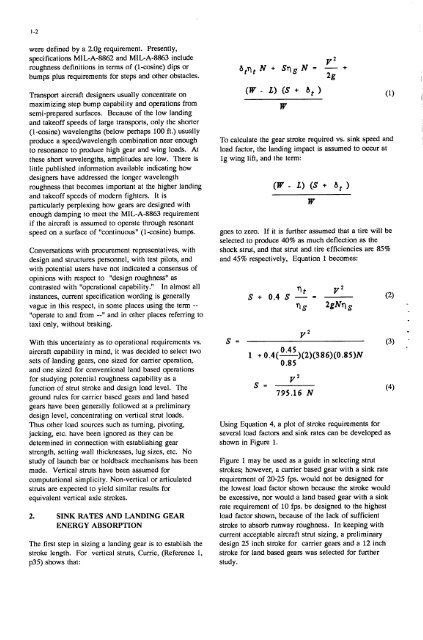
The first step in sizing a landing gear is to establish the<br />
stroke length. For vertical struts, Currie, (Reference 1,<br />
p35) shows that:<br />
W<br />
To calculate the gear stroke required vs. sink speed and<br />
load factor, the landing impact is assumed to occur at<br />
lg wing lift, and the term:<br />
goes to zero. If it is further assumed that a tire will be<br />
selected to produce 40% as much deflection as the<br />
shock strut, and that strut and.tire efficiencies are 85%<br />
and 45% respectively, Equation 1 becomes:<br />
W<br />
V2<br />
S = (3)<br />
0.45<br />
1 + 0.4(-)(2)(386)(0.85)N<br />
0.85<br />
V2<br />
S = 795.16 N<br />
Using Equation 4, a plot of stroke requirements for<br />
several load factors and sink rates can be developed as<br />
shown in Figure 1.<br />
Figure 1 may be used as a guide in selecting strut<br />
strokes; however, a carrier based gear with a sink rate<br />
requirement of 20-25 fps. would not be designed for<br />
the lowest load factor shown because the stroke would<br />
be excessive, nor would a land based gear with a sink<br />
rate requirement of 10 fps. be designed to the highest<br />
load factor shown, because of the lack of sufficient<br />
stroke to absorb runway roughness. In keeping with<br />
current acceptable aircraft strut sizing, a preliminary<br />
design 25 inch stroke for carrier gears and a 12 inch<br />
stroke for land based gears was selected for further<br />
study.<br />
(4)


