

AGARD R-800 - FTP Directory Listing - Nato
AGARD R-800 - FTP Directory Listing - Nato
AGARD R-800 - FTP Directory Listing - Nato

You also want an ePaper? Increase the reach of your titles
YUMPU automatically turns print PDFs into web optimized ePapers that Google loves.
- -<br />
-<br />
- -<br />
In comparing these graphs it is noted that as the<br />
taxi speed increases from 80 to 90 knots a<br />
progressively longer period of time is required for the<br />
vibration to damp out. At 95 knots the gear has the<br />
onset of limit cycle shimmy. At 100 hots the limit<br />
cycle shimmy is definitely established. From these<br />
time histories it is seen that the shimmy oscillation<br />
frequency is about 27.06 HZ at 95 knots. When the<br />
actual aircraft was tested, it was found that the nose<br />
gear went into a sudden onset of shimmy at 92 knots<br />
and had a frequency of 27.5 HZ. Repeated testing of<br />
this landing gear, yielded reasonably consistent<br />
repeatability at this shimmy speed and frequency.<br />
In the course of the shimmy investigation for<br />
Fighter C, one very important point came to<br />
light concerning the measurement of landing gear<br />
shimmy parameters. The vendor's original analysis<br />
consistently indicated that this landing gear was stable<br />
at all taxi speeds. The analysis provided by the<br />
author indicated the 95 knot shimmy event at 27.06<br />
HZ. The question arose as to what was different<br />
between the two analyses. After review of the input<br />
data a primary cause of this difference was<br />
established. The stability critical parameters KT, K,,<br />
K,, and K, used in the vendor's analysis were<br />
obtained by rigidly mounting the landing gear in a<br />
fixture and measuring the resulting parameters.<br />
Whereas, the author's analysis took into consideration<br />
the softening effects of the landing gear mounted in a<br />
flexible fuselage and reduced the stiffness values<br />
supplied by the vendor. The amount of this<br />
reduction was largely based on experience with other<br />
landing gear.<br />
The reason for taking fuselage flexibility effects<br />
into consideration was based on some data obtained<br />
in another landing gear shimmy investigation.<br />
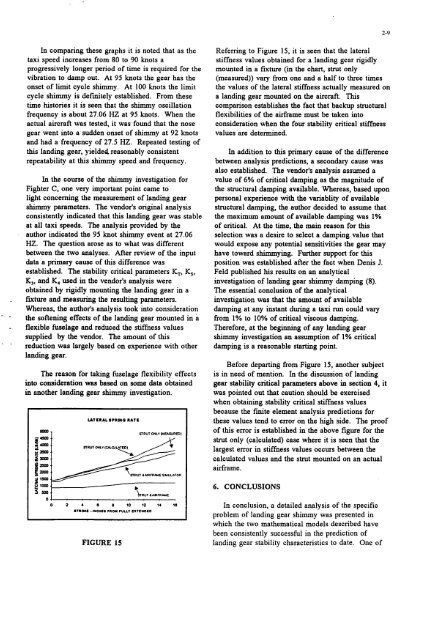
UTLRALSCRINO RATE<br />
FIGURE 15<br />
SRUT ONLY IYEAWREDI<br />
2-9<br />
Referring to Figure 15, it is seen that the lateral<br />
stiffness values obtained for a landing gear rigidly<br />
mounted in a fixture (in the chart, strut only<br />
(measured)) vary from one and a half to three times<br />
the values of the lateral stiffness actually measured on<br />
a landing gear mounted on the aircraft. This<br />
comparison establishes the fact that backup structural<br />
flexibilities of the airframe must be taken into<br />
consideration when the four stability critical stiffness<br />
values are determined.<br />
In addition to this primary cause of the difference<br />
between analysis predictions, a secondary cause was<br />
also established. The vendor's analysis assumed a<br />
value of 6% of critical damping as the magnitude of<br />
the structural damping available. Whereas, based upon<br />
personal experience with the variablity of available<br />
structural damping, the author decided to assume that<br />
the maximum amount of available damping was 1%<br />
of critical. At the time, the main reason for this<br />
selection was a desire to select a damping value that<br />
would expose any potential sensitivities the gear may<br />
have toward shimmying. Further support for this<br />
position was established after the fact when Denis J.<br />
Feld published his results on an analytical<br />
investigation of landing gear shimmy damping (8).<br />
The essential conclusion of the analytical<br />
investigation was that the amount of available<br />
damping at any instant during a taxi run could vary<br />
from 1% to 10% of critical viscous damping.<br />
Therefore, at the beginning of any landing gear<br />
shimmy investigation an assumption of 1% critical<br />
damping is a reasonable starting point.<br />
Before departing from Figure 15, another subject<br />
is in need of mention. In the discussion of landing<br />
gear stability critical parameters above in section 4, it<br />
was pointed out that caution should be exercised<br />
when obtaining stability critical stiffness values<br />
because the finite element analysis predictions for<br />
these values tend to error on the high side. The proof<br />
of this error is established in the above figure for the<br />
strut only (calculated) case where it is seen that the<br />
largest error in stiffness values occurs between the<br />
calculated values and the strut mounted on an actual<br />
airframe.<br />
6. CONCLUSIONS<br />
In conclusion, a detailed analysis of the specific<br />
problem of landing gear shimmy was presented in<br />
which the two mathematical models described have<br />
been consistently successful in the prediction of<br />
landing gear stability characteristics to date. One of


