- Page 1: 336853 AQARD-U-800 A\ T ADVISORY GR
- Page 4 and 5: The Mission of AGARD According to i
- Page 6 and 7: L’etude, l’homologation et la m
- Page 8 and 9: Preface Fully reliable procedures f
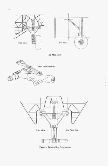
- Page 10 and 11: INTRODUCTION Landing gear is an inv
- Page 12 and 13: accordtng to the explanauon given i
- Page 14 and 15: - SUMMARY The differences in requir
- Page 16 and 17: Once preliminary stroke values are
- Page 18 and 19: increased inflation pressures and l
- Page 20 and 21: Figure 1. Stroke Requirements as a
- Page 24 and 25: SPACER \ METERING PIN UPPER BEARING
- Page 26 and 27: .!2 w 2 1.2e+5 1.0~5 8.0e+4 o 6.0~4
- Page 28: 400 350 i 300 P 250 d 200 $ W f 150
- Page 31 and 32: 2-2 K,, - Torsional Spring Rate of
- Page 33 and 34: 2-4 Q - Tire Roll Rotation about th
- Page 35 and 36: 2-6 landing gear shimmy analysis da
- Page 37 and 38: : 1 .I FIGURE 7 FIGURE 8 I - + I Y
- Page 39 and 40: 2-10 these models uses the Moreland
- Page 41 and 42: 2-12 KT TORSIONALSPRING RATE 8- 0 0
- Page 43 and 44: 3-2 therefore based on the requirem
- Page 45 and 46: 3-4 pistons within fractions of a s
- Page 47 and 48: 3-6 deceleration during brake initi
- Page 49 and 50: 3-8 Through interference of aerodyn
- Page 51 and 52: 3-10 STA 144.40 Fig. 2-1 Advanced T
- Page 53 and 54: 3-12 ............... X 1 Fig. 2 - 5
- Page 55 and 56: 200. 100. 0 W. 0.5 Fig. 3-5 Histogr
- Page 58 and 59: ANALYSIS AND CONTROL OF THE FLEXIBL
- Page 60 and 61: ~ - . govern the dynamic generation
- Page 62 and 63: tyre model Is .en orooosed I . in I
- Page 64 and 65: nm.1.1 Fig. 5.3-2 Transient respons
- Page 66 and 67: 0.012 0.014 0.01s Time ($1 Fig. 5.3
- Page 68 and 69: 1.2 I f ltlt I 1 .,( ~ ............
- Page 70: - - .. H.Tsukinoki, Antilock Brake
- Page 73 and 74:
5-2 NAsTRAN \ 7 1 A CAD I I I I Pro
- Page 75 and 76:
5-4 tion time actuator. The possibl
- Page 77 and 78:
5-6 Fed with this data, the BEAM pr
- Page 79 and 80:
5-8 given used for the excitation o
- Page 81 and 82:
5-10 5.2 Quasistochastic Excitation
- Page 83 and 84:
5-12 whole frequency range of inter
- Page 85 and 86:
6-2 The associated lateral spring c
- Page 87 and 88:
The expansion of this gives: 2.1 Th
- Page 89 and 90:
6-6 where MR represents the frictio
- Page 91 and 92:
6-8 The reaction force coming from
- Page 93 and 94:
6-10 Although the solution of the M
- Page 95 and 96:
6-12 brake force and self aligning
- Page 97 and 98:
6-14 For simulation respectively pr
- Page 99 and 100:
6-16 10 1 LMPLITUDE (l/degree) 0.1
- Page 101 and 102:
6-18 Massfactor MR [Nms2/degr.] 0,0
- Page 103 and 104:
6-20 5 Numerical method of investig
- Page 105 and 106:
6-22 numerical procedure, however,
- Page 107 and 108:
6-24 [Will871 [ W ill8 91 (Will951
- Page 109 and 110:
1-2 These examples occurred over IO
- Page 111 and 112:
5. DASH 8 MAIN LANDING GEAR SHIMMY
- Page 113 and 114:
develop the equations of motion. Th
- Page 115 and 116:
E 9
- Page 117 and 118:
7-10 .
- Page 119 and 120:
7-12 I 1% 6 !I i 3 > t a a 5? Y
- Page 121 and 122:
8-2 For larger deformations as they
- Page 123 and 124:
8-4 6. COMPUTATION OF THE LANDING I
- Page 125 and 126:
8-6 total tire loads at the centre
- Page 127 and 128:
8-8 E 30 s - 10 g 20 0 unstable . .
- Page 130 and 131:
- INFLUENCE OF NONLINEARITY ON THE
- Page 132 and 133:
- The solution is of the form : X =
- Page 134 and 135:
Frequency responses ofwtion model f
- Page 136 and 137:
(% These 4 integdons can be compute
- Page 138 and 139:
5.1.2 Structural description of lan
- Page 140:
o.O(r . 1 J/! ,....... ' ..........
- Page 143 and 144:
10-2 MSD = steering damper exponent
- Page 145 and 146:
10-4 TABLE 1 - Degrees of Freedom S
- Page 147 and 148:
10-6 A total of three degrees of fr
- Page 149 and 150:
10-8 3.1.3. Translational Kinematic
- Page 151 and 152:
10-10 FIXED ADAPTER Fig. 7. Steerin
- Page 153 and 154:
10-12 0 - o.5oot+oo 0.000E+00 . 0 -
- Page 157 and 158:
a@- NATO @ OTAN 7 RUE ANCELLE 92200