Foundations for Vibrating Machines - Shamsher Prakash Foundation
Foundations for Vibrating Machines - Shamsher Prakash Foundation
Foundations for Vibrating Machines - Shamsher Prakash Foundation

Create successful ePaper yourself
Turn your PDF publications into a flip-book with our unique Google optimized e-Paper software.
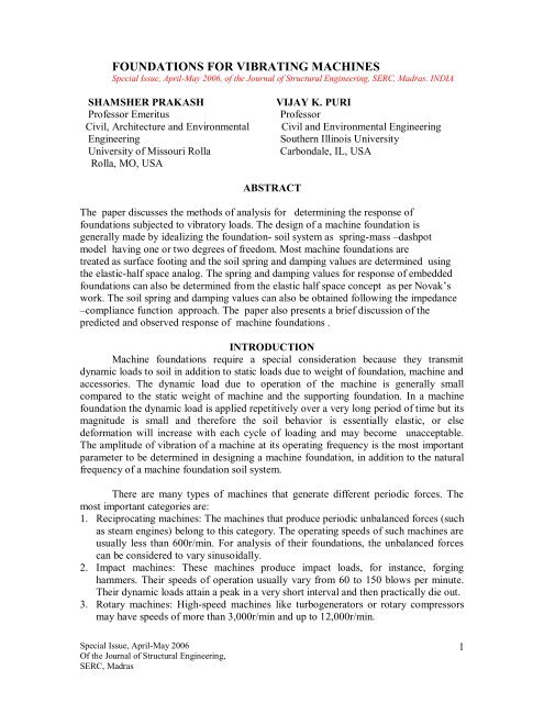
FOUNDATIONS FOR VIBRATING MACHINES<br />
Special Issue, April-May 2006, of the Journal of Structural Engineering, SERC, Madras. INDIA<br />
SHAMSHER PRAKASH VIJAY K. PURI<br />
Professor Emeritus Professor<br />
Civil, Architecture and Environmental Civil and Environmental Engineering<br />
Engineering Southern Illinois University<br />
University of Missouri Rolla Carbondale, IL, USA<br />
Rolla, MO, USA<br />
Special Issue, April-May 2006<br />
Of the Journal of Structural Engineering,<br />
SERC, Madras<br />
ABSTRACT<br />
The paper discusses the methods of analysis <strong>for</strong> determining the response of<br />
foundations subjected to vibratory loads. The design of a machine foundation is<br />
generally made by idealizing the foundation- soil system as spring-mass –dashpot<br />
model having one or two degrees of freedom. Most machine foundations are<br />
treated as surface footing and the soil spring and damping values are determined using<br />
the elastic-half space analog. The spring and damping values <strong>for</strong> response of embedded<br />
foundations can also be determined from the elastic half space concept as per Novak‟s<br />
work. The soil spring and damping values can also be obtained following the impedance<br />
–compliance function approach. The paper also presents a brief discussion of the<br />
predicted and observed response of machine foundations .<br />
INTRODUCTION<br />
Machine foundations require a special consideration because they transmit<br />
dynamic loads to soil in addition to static loads due to weight of foundation, machine and<br />
accessories. The dynamic load due to operation of the machine is generally small<br />
compared to the static weight of machine and the supporting foundation. In a machine<br />
foundation the dynamic load is applied repetitively over a very long period of time but its<br />
magnitude is small and there<strong>for</strong>e the soil behavior is essentially elastic, or else<br />
de<strong>for</strong>mation will increase with each cycle of loading and may become unacceptable.<br />
The amplitude of vibration of a machine at its operating frequency is the most important<br />
parameter to be determined in designing a machine foundation, in addition to the natural<br />
frequency of a machine foundation soil system.<br />
There are many types of machines that generate different periodic <strong>for</strong>ces. The<br />
most important categories are:<br />
1. Reciprocating machines: The machines that produce periodic unbalanced <strong>for</strong>ces (such<br />
as steam engines) belong to this category. The operating speeds of such machines are<br />
usually less than 600r/min. For analysis of their foundations, the unbalanced <strong>for</strong>ces<br />
can be considered to vary sinusoidally.<br />
2. Impact machines: These machines produce impact loads, <strong>for</strong> instance, <strong>for</strong>ging<br />
hammers. Their speeds of operation usually vary from 60 to 150 blows per minute.<br />
Their dynamic loads attain a peak in a very short interval and then practically die out.<br />
3. Rotary machines: High-speed machines like turbogenerators or rotary compressors<br />
may have speeds of more than 3,000r/min and up to 12,000r/min.<br />
1
A suitable foundation is selected, depending upon the type of machine. For<br />
compressors and reciprocating machines, a block foundation is generally provided<br />
(Fig.1a). Such a foundation consists of a pedestal resting on a footing. If two or more<br />
machines of similar type are to be installed in a shop, these can profitably be mounted on<br />
one continuous mat.<br />
A block foundation has a large mass and, there<strong>for</strong>e, a smaller natural frequency.<br />
However, if a relatively lighter foundation is desired, a box or a caisson type foundation<br />
may be provided. (Fig.1b) The mass of the foundation is reduced and its natural<br />
frequency increases. Hammers may also be mounted on block foundations, but their<br />
details would be quite different than those <strong>for</strong> reciprocating machines.<br />
Steam turbines have complex foundations that may consist of a system of walls<br />
columns, beams and slabs. (Fig.1c) Each element of such a foundation is relatively<br />
flexible as compared to a rigid block and box or a caisson-type foundation.<br />
The analysis of a block foundation is relatively simple as compared to a complex<br />
foundation. There are several methods of analysis <strong>for</strong> both the block and the complex<br />
foundations. The criteria <strong>for</strong> designing machine foundations shall be discussed first<br />
followed by the methods of analysis.<br />
Figure 1. Types of Machine <strong><strong>Foundation</strong>s</strong> (a) Block foundations. (b) Box or caisson<br />
foundations. (c) Complex foundations<br />
Special Issue, April-May 2006<br />
Of the Journal of Structural Engineering,<br />
SERC, Madras<br />
CRITERIA FOR DESIGN<br />
A machine foundation should meet the following conditions <strong>for</strong> satisfactory per<strong>for</strong>mance:<br />
2
Static loads<br />
1. It should be safe against shear failure<br />
2. It should not settle excessively<br />
These requirements are similar to those <strong>for</strong> all other foundations.<br />
Dynamic loads<br />
1. There should be no resonance; that is, the natural frequency of the machinefoundation-soil<br />
system should not coincide with the operating frequency of the<br />
machine. In fact, a zone of resonance is generally defined and the natural frequency<br />
of the system must lie outside this zone. The foundation is high tuned when its<br />
fundamental frequency is greater than the operating speed or low tuned when its<br />
fundamental frequency is lower than the operating speed. This concept of a high or<br />
low tuned foundation is illustrated in Fig..2.<br />
2. The amplitudes of motion at operating frequencies should not exceed the limiting<br />
amplitudes, which are generally specified by machine manufacturers. If the computed<br />
amplitude is within tolerable limits, but the computed natural frequency is close to the<br />
operating frequency, it is important that this situation be avoided.<br />
3. The natural frequency of the foundation –soil system should not be whole number<br />
multiple of the operating frequency of the machine to avoid resonance with the higher<br />
harmonics.<br />
4. The vibrations must not be annoying to the persons working in the shops or damaging<br />
to the other precision machines. The nature of vibrations that are perceptible,<br />
annoying, or harmful depends upon the frequency of the vibrations and the amplitude<br />
of motion.<br />
The geometrical layout of the foundation may also be influenced by the operational<br />
requirements of the machine. The failure condition of a machine foundation is reached<br />
when its motion exceeds a limiting value which may be based on acceleration , velocity<br />
or amplitude. . Richart (1962) defined the failure criteria in terms of limiting<br />
displacement amplitudes at a given frequency. The limiting or permissible amplitudes can<br />
be established from Fig. 3 (Blake, 1964), who also introduced the concept of service<br />
factor.<br />
Special Issue, April-May 2006<br />
Of the Journal of Structural Engineering,<br />
SERC, Madras<br />
3
Special Issue, April-May 2006<br />
Of the Journal of Structural Engineering,<br />
SERC, Madras<br />
Figure2. Tuning of a foundation<br />
4
Figure 3. Limiting amplitudes of vibrations <strong>for</strong> a particular frequency.<br />
(Blake, 1964)<br />
Criterion <strong>for</strong> vibration of rotating machinery. Explanation of classes :<br />
AA Dangerous. Shut it down now to avoid danger<br />
A Failure is near. Correct within two days to avoid breakdown.<br />
B Faulty. correct it within 10 days to save maintenance dollars.<br />
C Minor faults. Correction wastes dollars.<br />
D No faults. Typical new equipment.<br />
This is guide to aid judgment, not to replace it. Use common sense. Take account of all<br />
local circumstances. Consider: safety, labor costs, downtime costs. (after Blake, 1964.)<br />
Reproduced with permission from Hydrocarbon Processing, January 1964.<br />
The service factor indicates the importance of a machine in an installation. Typical values<br />
of service factors are listed in Table1. Using the concept of service factor, the criteria<br />
given in Fig. 3 can be used to define vibration limits <strong>for</strong> different classes of machines.<br />
Also, with the introduction of the service factor, Fig. 3 can be used to evaluate the<br />
Special Issue, April-May 2006<br />
Of the Journal of Structural Engineering,<br />
SERC, Madras<br />
5
per<strong>for</strong>mance of a wide variety of machines. The concept of service factor is explained by<br />
the following examples.<br />
A centrifuge has a 0.01 in (0.250 mm) double amplitude at 750 rpm. The value of the<br />
service factor from Table 1 is 2, and the effective vibration there<strong>for</strong>e is 2X 0.01 = 0.02 in<br />
(0.50 mm). This point falls in Class A in Fig. 3. The vibrations, there<strong>for</strong>e, are excessive,<br />
and failure is imminent unless the corrective steps are taken immediately. Another<br />
example is that of a link-suspended centrifuge operating at 1250 rpm that has0.00.30 in<br />
(0.075mm) amplitude with the basket empty. The service factor is 0.3, and the effective<br />
vibration is 0.00090 in (0.0225mm). This point falls in class C (Fig. 3) and indicates only<br />
minor fault.<br />
General in<strong>for</strong>mation <strong>for</strong> the operation of rotary machines is given in Table 2 (Baxter and<br />
Bernhard 1967).<br />
These limits are based on peak-velocity criteria alone and are represented by straight<br />
lines in Fig. 3<br />
Table 1. Service Factors a<br />
Single-stage centrifugal pump, electric 1<br />
motor, fan<br />
Typical chemical processing equipment, 1<br />
noncritical<br />
Turbine, turbogenerator, centrifugal 1.6<br />
compressor<br />
Centrifuge, stiff-shaft b; multistage<br />
2<br />
centrifugal pump<br />
Miscellaneous equipment, characteristics 2<br />
unknown<br />
Centrifuge, shaft-suspended, on shaft near 0.5<br />
basket<br />
Centrifuge, link-suspended, slung 0.3<br />
a Effective vibration - measured single amplitude vibration, in inches multiplied by the service factor. Machine tools<br />
are excluded. Values are <strong>for</strong> bolted-down equipment; when not bolted, multiply the service factor by 0.4 and use the<br />
product as the service factor. Caution: Vibration is measured on the bearing housing except, as stated.<br />
b Horizontal displacement basket housing.<br />
Table 2. General Machinery – Vibration Severity Criteria (Baxter and Bernhart, 1967)<br />
Horizontal Peak Velocity<br />
(in/sec)<br />
Machine Operation<br />
0.630 Very rough<br />
Special Issue, April-May 2006<br />
Of the Journal of Structural Engineering,<br />
SERC, Madras<br />
6
DEGREES OF FREEDOM OF A RIGID BLOCK FOUNDATION<br />
A typical concrete block is regarded as rigid as compared to the soil over which it rests.<br />
There<strong>for</strong>e, it may be assumed that it undergoes only rigid-body displacements and<br />
rotations. Under the action of unbalanced <strong>for</strong>ces, the rigid block may thus undergo<br />
displacements and oscillations as follows (Fig. 4)<br />
1. translation along Z axis<br />
2. translation along X axis<br />
3. translation along Y axis<br />
4. rotation about Z axis<br />
5. rotation about X axis<br />
6. rotation about Y axis<br />
Any rigid-body displacement of the block can be resolved into these six<br />
independent displacements. Hence, the rigid block has six degrees of freedom and six<br />
natural frequencies.<br />
Of six types of motion, translation along the Z axis and rotation about the Z axis<br />
can occur independently of any other motion. However, translation about the X axis (or Y<br />
axis) and rotation about the Y axis (or X axis) are coupled motions. There<strong>for</strong>e, in the<br />
analysis of a block, we have to concern ourselves with four types of motions. Two<br />
motions are independent and two are coupled. For determination of the natural<br />
frequencies, in coupled modes, the natural frequencies of the system in pure translation<br />
and pure rocking need to be determined. Also, the states of stress below the block in all<br />
four modes of vibrations are quite different. There<strong>for</strong>e, the corresponding soil-spring<br />
constants need to be defined be<strong>for</strong>e any analysis of the foundations can be undertaken.<br />
Special Issue, April-May 2006<br />
Of the Journal of Structural Engineering,<br />
SERC, Madras<br />
7
Special Issue, April-May 2006<br />
Of the Journal of Structural Engineering,<br />
SERC, Madras<br />
Figure 4.Modes of vibration of a rigid block foundation<br />
INFORMATION NEEDED FOR DESIGN<br />
The following in<strong>for</strong>mation is required and must be obtained <strong>for</strong> design of a<br />
machine foundation:<br />
1. Static weight of the machine and accessories.<br />
2. Magnitude and characteristics of dynamic loads imposed by the machine operation<br />
and their point of application<br />
3. The soil profile of the site and dynamic soil properties such as dynamic shear<br />
modulus and damping<br />
4. Trial dimensions of the foundation. These are generally supplied by the manufacturer.<br />
This will give the total static weight.<br />
5. An acceptable method of analysis i.e., a mathematical model to determine the<br />
response of the foundation-soil system<br />
6. A criteria <strong>for</strong> adequate design<br />
The above items are briefly discussed below:<br />
Dynamic Loads: The in<strong>for</strong>mation on dynamic loads and moments may be available from<br />
the manufacturer of the machine. It may be possible to determine the dynamic loads and<br />
moments <strong>for</strong> design of a machine foundation in some simple cases such as <strong>for</strong> the case of<br />
reciprocating and rotary machines.<br />
SOIL PROFILE AND DYNAMIC SOIL PROPERTIES<br />
8
Satisfactory design of a machine foundation needs in<strong>for</strong>mation on soil profile, depth of<br />
different layers, physical properties of soil and ground water level. This in<strong>for</strong>mation can<br />
be obtained by usual sub-surface exploration techniques. In addition, one must determine<br />
dynamic shear modulus, material damping, poisons ratio and mass density of soil <strong>for</strong><br />
dynamic analysis of the machine foundation. Dynamic shear modulus of a soil is<br />
generally determined from laboratory or field tests. Material damping can be determined<br />
from vibration tests on soil columns in the laboratory. The values of dynamic shear<br />
modulii and damping may be estimated from empirical estimations <strong>for</strong> preliminary<br />
design purposes. Geometrical damping is estimated from elastic half-space theory and<br />
appropriate analogs. Detailed discussion of determination of dynamic soil properties and<br />
interpretation of test is beyond the scope of this paper and a reference may be made to<br />
<strong>Prakash</strong> (1981) and <strong>Prakash</strong> and Puri (1981, 1988)<br />
Special Issue, April-May 2006<br />
Of the Journal of Structural Engineering,<br />
SERC, Madras<br />
TRIAL DIMENSIONS OF THE FOUNDATION<br />
The trial dimensions of the machine foundation are selected based on the requirements of<br />
the manufacturer, the machine shop and the machine per<strong>for</strong>mance and experience of the<br />
designer. These trial dimensions of the foundation are only the first step in the design and<br />
may need alteration after the analysis.<br />
METHODS OF ANALYSIS<br />
The analysis of machine foundation is usually per<strong>for</strong>med by idealizing it as a simple<br />
system as explained here. Figure 5 shows a schematic sketch of a rigid concrete block<br />
resting on the ground surface and supporting a machine. Let us assume that the operation<br />
of the machine produces a vertical unbalanced <strong>for</strong>ce which passes through the combined<br />
centre of gravity of the machine-foundation system. Under this condition, the foundation<br />
will vibrate only in the vertical direction about its mean position of static equilibrium.<br />
The vibration of the foundation results in transmission of waves through the soil. These<br />
waves carry energy with them. This loss of energy is termed „geometrical damping‟. The<br />
soil below the footing experiences cyclic de<strong>for</strong>mations and absorbs some energy which is<br />
termed „material damping‟. The material damping is generally small compared to the<br />
geometrical damping and may be neglected in most cases. However, material damping<br />
may also become important in some cases of machine foundation vibrations.<br />
The problem of a rigid block foundation resting on the ground surface, (Fig. 5a)<br />
may there<strong>for</strong>e be represented in a reasonable manner by a spring-mass-dashpot system<br />
shown in Fig. 5b. The spring in this figure is the equivalent soil spring which represents<br />
the elastic resistance of the soil below the base of the foundation. The dashpot represents<br />
the energy loss or the damping effect. The mass in Fig. 5b is the mass of the foundation<br />
block and the machine. If damping is neglected, a spring-mass system shown in Fig. 5c<br />
may be used to represent the problem defined in Fig. 5a. Single degree of freedom<br />
models shown in Fig. 5 b and c may in fact be used to represent the problem of machine<br />
foundation vibration in any mode of vibration if appropriate values of equivalent soil<br />
spring and damping constants are used. For coupled modes of vibration, as <strong>for</strong> combined<br />
rocking and sliding, two degree-of-freedom model is used as discussed later in the paper.<br />
9
m<br />
Soil stiffness<br />
and damping<br />
Pz Sinωt Pz Sin ωt Pz Sin ωt<br />
Figure 5. Vertical Vibrations of a Machine <strong>Foundation</strong> (a) Actual case, (b) Equivalent<br />
model with damping (c) Model without damping<br />
All foundations in practice are placed at a certain depth below the ground surface.<br />
As a result of this embedment, the soil resistance to vibration develops not only below the<br />
base of the foundation but also along the embedded portion of the sides of the foundation.<br />
Similarly the energy loss due to radiation damping will occur not only below the<br />
foundation base but also along the sides of the foundation. The type of models shown in<br />
Fig. 5 b and c may be used to calculate the response of embedded foundations if the<br />
equivalent soil spring and damping values are suitably modified by taking into account<br />
the behavior of the soil below the base and on the sides of the foundation.<br />
Several methods are available <strong>for</strong> analysis of vibration characteristics of machine<br />
foundations. The commonly used methods are<br />
1 Linear elastic spring method,<br />
2 Elastic half-space analogs method, and<br />
3 The impedance function method.<br />
kz<br />
1. The Linear Elastic Spring method (Barkan, 1962) treats the problem of<br />
foundation vibrations as spring- mass model , neglecting damping in the soil. The soil<br />
damping can be included if desired.<br />
2. The Elastic Half Space Analogs: The elastic half space theory can be used to<br />
determine the values of equivalent soil springs and damping then make use of theory of<br />
vibrations to determine the response of the foundation. These are known as the „the<br />
elastic half space analogs‟. They can be used <strong>for</strong> surface as well as embedded<br />
foundations. It may be mentioned here that the equivalent soil spring and damping values<br />
depend upon the ;<br />
Special Issue, April-May 2006<br />
Of the Journal of Structural Engineering,<br />
SERC, Madras<br />
m<br />
(a) (b) (c)<br />
cz<br />
kz<br />
m<br />
10
(i) type of soil and its properties,<br />
(ii) geometry and layout of the foundation, and<br />
(iii) nature of the foundation vibrations occasioned by unbalanced dynamic loads.<br />
3. The Impedance Function Method: They also provide vales of soil spring and damping<br />
<strong>for</strong> surface and embedded foundations.<br />
The solutions based on the elastic half space analog are commonly used <strong>for</strong> machine<br />
foundation design and are discussed first followed by the impedance function method.<br />
Elastic-half –space -analogs<br />
Surface <strong><strong>Foundation</strong>s</strong><br />
Vertical vibrations: The problem of vertical vibrations is idealized as a single degree<br />
freedom system with damping as shown in Fig. 13.15b. Hsieh (1962) and Lysmer and<br />
Richart (1966) have provided a solution .The equation of vibration is:<br />
Special Issue, April-May 2006<br />
Of the Journal of Structural Engineering,<br />
SERC, Madras<br />
2<br />
3.<br />
4ro<br />
4Gro<br />
� z�<br />
Gz�<br />
s P sin t<br />
1<br />
1 v 1 v<br />
m z<br />
Where ro = radius of the foundation (For non-circular foundations, appropriate<br />
equivalent radius may be used, see Eqs. 40-42).<br />
The equivalent spring <strong>for</strong> vertical vibrations is given by<br />
And the damping cz is given by<br />
k<br />
z<br />
4Gr<br />
cz<br />
3.<br />
4ro<br />
.<br />
1 v<br />
G<br />
The damping constant <strong>for</strong> vertical vibrations z is given by<br />
z<br />
1<br />
B<br />
o<br />
v<br />
0.<br />
425<br />
In which Bz is known as the modified mass ratio, given by<br />
z<br />
1 v m<br />
B z .<br />
5<br />
4 r<br />
3<br />
o<br />
2<br />
3<br />
4<br />
11
The undamped natural frequency of vertical vibrations may now be obtained using Eqs. 6<br />
and 7.<br />
Special Issue, April-May 2006<br />
Of the Journal of Structural Engineering,<br />
SERC, Madras<br />
f<br />
k z<br />
nz 6<br />
m<br />
nz<br />
1<br />
2<br />
k z<br />
m<br />
In which nz = the circular natural frequency (undamped) of the soil foundation system<br />
in vertical vibration (rad/sec) and f nz = natural frequency of vertical vibrations (Hz).<br />
The amplitude of vertical vibration is obtained as:<br />
A z<br />
k z 1<br />
Pz<br />
2 2<br />
r 2<br />
2<br />
zr<br />
k z 1 / nz<br />
2<br />
Pz<br />
2<br />
2 z / nz<br />
2<br />
1/<br />
2 8<br />
Sliding vibrations<br />
The equation of the analog <strong>for</strong> sliding is (Fig. 6)<br />
PxSinωt<br />
m<br />
Soil stiffness<br />
and damping<br />
a<br />
� x�<br />
c x�<br />
k x P sin t<br />
9<br />
m x x z<br />
Figure 6. Sliding Vibrations of a Rigid Block (a) Actual case (b) Equivalent model<br />
Hall (1967) defined the modified mass ratio <strong>for</strong> sliding as:<br />
where ro = radius of the foundation .<br />
PxSinωt<br />
7 8v<br />
m<br />
B x<br />
10<br />
32 1 v pr<br />
3<br />
o<br />
m<br />
b<br />
kx<br />
cx<br />
7<br />
12
The expressions <strong>for</strong> the equivalent spring and damping factors are as follows:<br />
The equivalent spring<br />
And the equivalent damping<br />
The damping ratio x is given by<br />
Special Issue, April-May 2006<br />
Of the Journal of Structural Engineering,<br />
SERC, Madras<br />
k<br />
x<br />
32 1 v<br />
Gr<br />
7 8v<br />
18.<br />
4 1 v<br />
cx ro<br />
7 8v<br />
x<br />
e<br />
x<br />
o<br />
2<br />
cx 0.<br />
2875<br />
c B<br />
The undamped natural frequency of sliding vibration may be obtained as follows:<br />
f<br />
G<br />
k x<br />
nx 14a<br />
m<br />
nx<br />
1<br />
2<br />
k<br />
x<br />
m<br />
In which ωnx = the circular natural frequency (undamped) in sliding vibrations and f nx =<br />
natural frequency of sliding vibrations (Hz).<br />
The damped amplitude in sliding is obtained as:<br />
x<br />
A x<br />
15<br />
2<br />
2<br />
2<br />
k<br />
x<br />
1<br />
nx<br />
Rocking Vibrations: A rigid block foundation undergoing rocking vibrations due to an<br />
exciting moment M y sin t is shown in Fig. 7.<br />
P<br />
Hall (1967) proposed an equivalent mass-spring-dashpot model that can be used to<br />
determine the natural frequency and amplitude of vibration of a rigid circular footing<br />
resting on an elastic half-space and undergoing rocking vibrations (Fig.7). The equivalent<br />
model is given in equation 16<br />
2<br />
x<br />
nx<br />
11<br />
12<br />
13<br />
14b<br />
� � c � k M sin t<br />
16<br />
M mo<br />
y<br />
13
In which k = spring constant <strong>for</strong> rocking, c = damping constant and M mo = mass<br />
moment of inertia of the foundation and machine about the axis of rotation through the<br />
base.<br />
2<br />
M mo M m mL<br />
17<br />
Where M m = mass moment of inertia of foundation and machine about an axis passing<br />
through the centroid of the system and parallel to the axis of rotation and L = the height<br />
of the centroid above the base.<br />
The terms k and c can be obtained as follows:<br />
And<br />
in which r 0 = radius.<br />
Special Issue, April-May 2006<br />
Of the Journal of Structural Engineering,<br />
SERC, Madras<br />
c<br />
k<br />
8Gr<br />
3 1<br />
0.<br />
8r<br />
1<br />
v<br />
3<br />
o<br />
4<br />
o<br />
v<br />
1<br />
G<br />
B in Eq. 19 is known as the modified inertia ratio which obtained as follows:<br />
B<br />
3 1 v M<br />
B 20<br />
8 r<br />
mo<br />
5<br />
o<br />
Figure 7. Rocking vibrations of a rigid block under excitation due to an applied moment<br />
18<br />
19<br />
14
The damping factor is given by<br />
Special Issue, April-May 2006<br />
Of the Journal of Structural Engineering,<br />
SERC, Madras<br />
c<br />
c<br />
c<br />
1<br />
0.<br />
15<br />
The undamped natural frequency of rocking<br />
B<br />
B<br />
k<br />
n rad / sec<br />
22<br />
M<br />
Damped amplitude of rocking vibrations A is given by Eq. 23<br />
mo<br />
M y<br />
A 23<br />
k<br />
1<br />
n<br />
2<br />
2<br />
Torsional vibrations: A block foundation undergoing torsional vibrations is shown in<br />
Fig.8. Non-uni<strong>for</strong>m shearing resistance is mobilized during such vibrations. The analog<br />
solution <strong>for</strong> torsional vibrations is provided by Richart et al, (1970).<br />
2<br />
n<br />
2<br />
21<br />
15
Figure 8. Torsional vibrations of rigid block: (a) Block subjected to horizontal moment.<br />
(b) Development of nonuni<strong>for</strong>m shear below the base<br />
The equation of motion is<br />
Special Issue, April-May 2006<br />
Of the Journal of Structural Engineering,<br />
SERC, Madras<br />
i t<br />
� � mz C k M ze<br />
24<br />
M �<br />
In which M mz = mass moment of inertia of the machine and foundation about the vertical<br />
axis of rotation (polar mass moment of inertia). The spring constant k and the damping<br />
constant c are given by (Richart and Whitman, 1967):<br />
where r o ( ro<br />
) = equivalent radius..<br />
16 3<br />
k Gro<br />
25<br />
3<br />
c<br />
1.<br />
6r<br />
1<br />
The undamped natural frequency n of the torsional vibrations is given by<br />
The amplitude of vibration A is given by<br />
In which the damping ratio is given by<br />
4<br />
o<br />
B<br />
G<br />
k<br />
n rad / sec<br />
27<br />
M<br />
1<br />
n<br />
mz<br />
z<br />
A 28<br />
2<br />
2<br />
2<br />
k<br />
1<br />
0.<br />
5<br />
2B<br />
The modified inertia ratio B is given by<br />
mz<br />
5<br />
o<br />
M<br />
2<br />
M<br />
B 30<br />
r<br />
n<br />
26<br />
29<br />
16
Combined rocking and sliding: The problem of combined rocking and sliding is shown<br />
schematically in Fig. 9. The equations of motion are written as:<br />
m<br />
m<br />
Special Issue, April-May 2006<br />
Of the Journal of Structural Engineering,<br />
SERC, Madras<br />
�<br />
i t<br />
� x�<br />
cx<br />
x�<br />
kx<br />
x Lc x Lk x Pxe<br />
31<br />
M ��<br />
2<br />
c L C �<br />
2<br />
k L k Lc x�<br />
x<br />
x<br />
The undamped natural frequencies <strong>for</strong> this case can be obtained from Eq. 33.<br />
4<br />
n<br />
2<br />
nx<br />
2<br />
n 2<br />
n<br />
2<br />
nx.<br />
2<br />
n<br />
0<br />
33<br />
In which<br />
mo<br />
x<br />
Lk<br />
x<br />
x<br />
M<br />
M m<br />
34<br />
M<br />
Figure 9. Block subjected to the action of simultaneous vertical Pz(t), horizontal Px(t)<br />
<strong>for</strong>ces and moment My(t)<br />
The damping in rocking and sliding modes will be different. <strong>Prakash</strong> and Puri (1988)<br />
developed equations <strong>for</strong> determination of vibration amplitudes <strong>for</strong> this case. Damped<br />
amplitudes of rocking and sliding occasioned by an exciting moment M y can be obtained<br />
as follows:<br />
2<br />
1/<br />
2<br />
2<br />
2<br />
M y nx 2 x . nx . L<br />
Ax<br />
356<br />
2<br />
M<br />
m<br />
y<br />
e<br />
i<br />
t<br />
32<br />
17
The value of<br />
Special Issue, April-May 2006<br />
Of the Journal of Structural Engineering,<br />
SERC, Madras<br />
4<br />
2<br />
1/<br />
2<br />
2<br />
2 2<br />
M y nx 2 x nx<br />
A 36<br />
2<br />
M<br />
2 is obtained from Eq. 38<br />
2<br />
x<br />
nx<br />
4<br />
2<br />
n<br />
m<br />
2<br />
2<br />
n<br />
2<br />
2<br />
nx<br />
n<br />
Damped amplitudes of rocking and sliding occasioned by a horizontal <strong>for</strong>ce Px are given<br />
by Eqs.38 and 39<br />
2<br />
2 2 2<br />
2<br />
1 M m k L k x 4 k M mo L x k xm<br />
Px<br />
Ax<br />
38<br />
2<br />
mM<br />
And<br />
m<br />
4<br />
x<br />
2<br />
nx<br />
1<br />
2<br />
nx<br />
2<br />
2<br />
Px<br />
L nx nx 4 x<br />
A 39<br />
2<br />
M<br />
m<br />
In case the footing is subjected to the action of a moment and a horizontal <strong>for</strong>ce,<br />
the resulting amplitudes of sliding and rocking may be obtained by adding the<br />
corresponding solutions from Eqs.35, 36, 38 and 39.<br />
Effect of shape of the foundation on its response: The solutions from the elastic halfspace<br />
theory were developed <strong>for</strong> a rigid circular footing. The vibratory response <strong>for</strong> noncircular<br />
foundations may be obtained using the concept of equivalent circular footing.<br />
The equivalent radius of the foundation <strong>for</strong> different modes of vibration is not the same.<br />
For vertical and sliding vibrations:<br />
For rocking vibrations<br />
1/<br />
2<br />
2<br />
n<br />
2<br />
ab<br />
o roz<br />
r<br />
40<br />
r ox<br />
1/<br />
4<br />
3<br />
ba<br />
ro ro<br />
41<br />
3<br />
1/<br />
2<br />
2<br />
nx<br />
2<br />
n<br />
2<br />
2<br />
1/<br />
2<br />
37<br />
18
For torsional vibrations<br />
.<br />
Special Issue, April-May 2006<br />
Of the Journal of Structural Engineering,<br />
SERC, Madras<br />
1/<br />
4<br />
2 2<br />
ab a b<br />
ro ro<br />
42<br />
6<br />
<strong><strong>Foundation</strong>s</strong> on elastic layer: The elastic half-space solution is based on the assumption<br />
of a homogenous soil deposit. In practice soils are layered media with each layer having<br />
different characteristics. An underlying rock below a soil layer may cause large<br />
magnification of amplitude of vibration because of its ability to reflect wave energy back<br />
into the soil supporting the foundation. Special care should be taken during design to<br />
overcome this effect.<br />
Embedded <strong><strong>Foundation</strong>s</strong><br />
The embedment of the foundation results in an increased contact between the soil<br />
and the vertical faces of the foundation. This results in increased mobilization of soil<br />
reactions which now develop not only below the base of the foundation but also along the<br />
vertical sides of the foundation in contact with the soil. The overall stiffness offered by<br />
the soil there<strong>for</strong>e increases. Similarly, more energy is carried away by the waves which<br />
now originate not only from the base of the foundation but also from the vertical faces of<br />
the foundation in contact with the soil. This results in an increased geometrical damping.<br />
The elastic half-space method <strong>for</strong> calculating the response of embedded foundations was<br />
developed by Novak and Beredugo (1971, 1972), Beredugo (1976), Novak and Beredugo<br />
(1972) and Novak and Sachs (1973) by extending the earlier solution of Baranov (1967).<br />
The solution is based upon the following assumptions:<br />
1) The footing is rigid.<br />
2) The footing is cylindrical.<br />
3) The base of the footing rests on the surface of a semi-infinite elastic half-space.<br />
4) The soil reactions at the base are independent of the depth of embedment.<br />
5) The soil reactions on the side are produced by an independent elastic layer lying<br />
above the level of the footing base.<br />
6) The bond between the sides of the footing and the soil is perfect.<br />
Based on the above assumptions, the expressions <strong>for</strong> equivalent spring and damping<br />
values <strong>for</strong> different modes of vibrations were obtained. The soil properties below the base<br />
of foundation were defined in terms of the shear modulus G, Poisson‟s ratio v and the<br />
mass density of the soil . The properties of the soil on the sides of the foundation were<br />
similarly defined in terms of shear modulus G s , the Poisson‟s ratio vs and the mass<br />
density s . The values of equivalent spring and damping <strong>for</strong> vertical, sliding, rocking and<br />
torsional modes of vibrations were then obtained. The values of spring and damping were<br />
found to be frequency dependent. However, it was found that within the range of<br />
practical interest, the equivalent spring and damping may be assumed to be frequency<br />
19
independent. This range was defined using a dimensional frequency ratio a o . The<br />
dimensional frequency ratio is defined as:<br />
Special Issue, April-May 2006<br />
Of the Journal of Structural Engineering,<br />
SERC, Madras<br />
r<br />
o<br />
a o<br />
43<br />
vs<br />
in which = operating speed of the machine in rad/sec.<br />
The values of equivalent frequency-independent spring and damping <strong>for</strong> the<br />
embedded foundation <strong>for</strong> the vertical, sliding, rocking and torsional modes are given in<br />
the Tables 3 and 4. The vibratory response of the foundation may then be calculated<br />
using the appropriate equations as <strong>for</strong> the elastic half-space analog <strong>for</strong> the surface<br />
foundations after replacing the spring stiffness and damping values with the<br />
corresponding values <strong>for</strong> the embedded foundations.<br />
The response of a foundation undergoing coupled rocking and sliding vibrations<br />
may similarly be calculated. However, some cross-coupling stiffness and damping terms<br />
appear in the analysis of embedded foundations according to the elastic half-space<br />
method (Beredugo and Novak, 1972). The necessary equations <strong>for</strong> calculating the<br />
stiffness, damping, natural frequencies and amplitude of vibrations are summarized in<br />
Table 5.<br />
For a given size and geometry of the foundation, and the soil properties, the stiffness and<br />
damping values <strong>for</strong> an embedded foundation are much higher than those <strong>for</strong> a surface<br />
foundation. The natural frequency of an embedded foundation will be higher and its<br />
amplitude of vibration will be smaller compared to a foundation resting on the surface.<br />
Increasing the depth of embedment may be a very effective way of reducing the vibration<br />
amplitudes. The beneficial effects of embedment, however, depend on the quality of<br />
contact between the embedded sides of the foundation and the soil. The quality of contact<br />
between the sides of the foundation and the soil depends upon the nature of the soil, the<br />
method of soil placement and its compaction, and the temperature. Reduced values of soil<br />
parameters should be used <strong>for</strong> the soil on the sides of the foundation if any „gap‟ is likely<br />
to develop between the foundation sides and the soil, especially near the ground surface.<br />
Impedance Function Method<br />
(Surface and Embedded <strong><strong>Foundation</strong>s</strong>)<br />
The dynamic response of a foundation may be calculated by the impedance function<br />
method. (Gazettas 1983, 1991a, b, Dobry and Gazettas 1985) This method is briefly<br />
discussed here. The geometry of rigid massless foundation considered by Gazettas<br />
(1991b) is shown in Fig.10a <strong>for</strong> a surface foundation in Fig.10b <strong>for</strong> an embedded<br />
foundation. The response of this foundation due to a sinusoidal excitation can be obtained<br />
following theory of vibration after the appropriate dynamic impedance functions S<br />
<strong>for</strong> the frequencies of interest have been determined.<br />
The dynamic impedance is a function of the foundation soil system and the nature<br />
and the type of exciting loads and moments. For each particular case, of harmonic<br />
excitation, the dynamic impedance is defined as the ratio between <strong>for</strong>ce (or moment) R<br />
and the resulting steady-state displacement (or rotations) U at the centriod of the base of<br />
the massless foundation. For example, the vertical impedance is defines by<br />
20
Special Issue, April-May 2006<br />
Of the Journal of Structural Engineering,<br />
SERC, Madras<br />
Rz<br />
I<br />
S z 44<br />
U I<br />
z<br />
In which Rz I Rz<br />
exp i t and is the harmonic vertical <strong>for</strong>ce; and U z I U z exp i t<br />
harmonic vertical displacement of the soil-foundation interface. The quantity R z is the<br />
total dynamic soil reaction against the foundation and includes normal traction below the<br />
base and frictional resistance along the vertical sides of the foundation.<br />
The following impedances may similarly be defined: S y = lateral sliding or<br />
swaying impedance (<strong>for</strong>ce-displacement ratio), <strong>for</strong> horizontal motion in the y- direction;<br />
S = longitudinal swaying or sliding impedance (<strong>for</strong>ce-displacement ratio), <strong>for</strong> horizontal<br />
x<br />
motion along x-direction; S rx = rocking impedance (moment-rotation ratio), <strong>for</strong> rotational<br />
motion about the centroidal x-axis of the foundation base.<br />
21
Table 3. Value of equivalent spring and damping constants <strong>for</strong> embedded foundations (Beredugo and Novak 1972, Novak<br />
and Beredugo 1972, Novak and Sachs 1973)<br />
Damping<br />
ratio<br />
Equivalent<br />
Damping constant<br />
Equivalent<br />
spring<br />
The values of frequency<br />
independent parameters ‟s<br />
<strong>for</strong> the elastic space are<br />
given in Table 4.<br />
Special Issue, April-May 2006<br />
Of the Journal of Structural Engineering,<br />
SERC, Madras<br />
The values of frequency<br />
independent parameters ‟s<br />
<strong>for</strong> the elastic space are<br />
given in Table 4.<br />
ro and h refer to radius and<br />
depth of embedment of the<br />
foundation respectively<br />
22
Mode of<br />
Vibration<br />
Special Issue, April-May 2006<br />
Of the Journal of Structural Engineering,<br />
SERC, Madras<br />
Vertical<br />
Sliding<br />
Rocking<br />
Torsional<br />
or Yawing<br />
23
Table4. Values of elastic half-space and side layer parameters <strong>for</strong> embedded foundations<br />
(Beredugo and Novak 1972, Novak and Beredugo 1972, Novak and Sachs 1973)<br />
Mode of<br />
vibration<br />
Poisson’s<br />
ratio v<br />
Vertical 0.0<br />
0.25<br />
0.5<br />
Sliding 0<br />
0.25<br />
0.4<br />
0.5<br />
Special Issue, April-May 2006<br />
Of the Journal of Structural Engineering,<br />
SERC, Madras<br />
Elastic half-space<br />
Frequencyindependent<br />
constant<br />
parameter<br />
C 1<br />
C<br />
C<br />
C<br />
C<br />
C<br />
2<br />
1<br />
2<br />
1<br />
2<br />
C x1<br />
C x2<br />
C x1<br />
C x2<br />
3.<br />
90<br />
3.<br />
50<br />
5.<br />
20<br />
5.<br />
00<br />
7.<br />
50<br />
6.<br />
80<br />
4.<br />
30<br />
2.<br />
70<br />
5.<br />
10<br />
0.<br />
43<br />
Rocking 0 C 2.<br />
50<br />
Torsional<br />
or yawing<br />
C<br />
1<br />
0.<br />
43<br />
Any value C 4.<br />
3<br />
C<br />
2<br />
1<br />
2<br />
0.<br />
7<br />
Validity range<br />
0 a 0<br />
1.<br />
5<br />
(<strong>for</strong> all values<br />
of v)<br />
0 a 0<br />
0 a 0<br />
0 0<br />
0 0<br />
2.<br />
0<br />
2.<br />
0<br />
Frequencyindependent<br />
constant<br />
parameter<br />
S 1<br />
2.<br />
70<br />
S 2 6.<br />
7<br />
(<strong>for</strong> all<br />
values of v)<br />
S x1<br />
S x2<br />
S x1<br />
S x2<br />
S x1<br />
S x2<br />
3.<br />
60<br />
8.<br />
20<br />
4.<br />
00<br />
9.<br />
10<br />
4.<br />
10<br />
10.<br />
60<br />
a 1.<br />
0 S 2.<br />
50<br />
S<br />
1<br />
2<br />
1.<br />
80<br />
(<strong>for</strong> any<br />
value of v)<br />
a 2.<br />
0 S 12.<br />
4<br />
S<br />
S<br />
S<br />
1<br />
1<br />
2<br />
2<br />
10.<br />
2<br />
2.<br />
0<br />
5.<br />
4<br />
Side layer<br />
Validity range<br />
0 a 0<br />
1.<br />
5<br />
(<strong>for</strong> all values<br />
of v)<br />
0 a 0<br />
0 a 0<br />
0 a 0<br />
0 a 0<br />
0 a 0<br />
0 a 0<br />
0 a 0<br />
0. 2 a 0<br />
0 a 0<br />
0. 2 a<br />
0<br />
1.<br />
5<br />
2.<br />
0<br />
1.<br />
5<br />
2.<br />
0<br />
1.<br />
5<br />
1.<br />
5<br />
2.<br />
0<br />
2.<br />
0<br />
2.<br />
0<br />
2.<br />
0<br />
24
Table5 Computation of response of an embedded foundation by elastic half-space method<br />
<strong>for</strong> coupled rocking and sliding (Beredugo and Novak 1972)<br />
Item<br />
Stiffness in<br />
k<br />
Gr<br />
h<br />
S<br />
s<br />
sliding xe o x1<br />
x1<br />
G ro<br />
Stiffness in<br />
C<br />
G<br />
Equation<br />
2<br />
2 2<br />
3 L Gs<br />
h Gs<br />
h h L hL<br />
rocking k e Gro<br />
C 1 Cx1<br />
S 1<br />
S<br />
2 2 2 x1<br />
ro<br />
G ro<br />
G ro<br />
3ro<br />
ro<br />
ro<br />
Crosscoupling<br />
stiffness<br />
Damping<br />
constant in<br />
sliding<br />
Damping<br />
constant in<br />
rocking<br />
Crosscoupling<br />
damping<br />
Frequency<br />
equation<br />
Amplitude in<br />
sliding<br />
(damped)<br />
Amplitude in<br />
rocking<br />
(damped)<br />
Various<br />
terms in<br />
equations <strong>for</strong><br />
A and A<br />
xe<br />
e<br />
k<br />
c<br />
c<br />
c<br />
x e<br />
xe<br />
e<br />
x e<br />
k<br />
A<br />
A<br />
xe<br />
xe<br />
1<br />
2<br />
e<br />
k<br />
k<br />
m<br />
P<br />
x<br />
M<br />
e<br />
c<br />
Gr<br />
o<br />
Gr<br />
Gr<br />
y<br />
e<br />
2<br />
n<br />
2<br />
o<br />
4<br />
o<br />
Gr<br />
LC<br />
k<br />
2<br />
1<br />
2<br />
1<br />
M<br />
m<br />
C<br />
2<br />
o<br />
C<br />
e<br />
2<br />
1<br />
2<br />
1<br />
m<br />
M<br />
P<br />
x<br />
y<br />
x1<br />
x2<br />
2<br />
LC<br />
M<br />
2<br />
2<br />
2<br />
2<br />
2<br />
c<br />
2<br />
2<br />
2<br />
2<br />
x e<br />
G<br />
x2<br />
P<br />
m<br />
s<br />
G<br />
h<br />
r<br />
o<br />
L<br />
r<br />
o<br />
M<br />
P<br />
2<br />
n<br />
x<br />
k<br />
y<br />
h<br />
r<br />
2<br />
o<br />
C<br />
h<br />
r<br />
o<br />
k<br />
s<br />
x2<br />
k<br />
The values of parameters Cx1 , Cx<br />
2,<br />
C 1,<br />
C 2,<br />
S x1,<br />
S x2<br />
, S 1,<br />
and S 2 are given in Table 4.<br />
L is the height of the centre of gravity above the base.<br />
The horizontal <strong>for</strong>ce Px and the moment M y act at the centre of gravity of the foundation.<br />
The equations given in this table are used <strong>for</strong> coupled rocking and sliding of embedded foundations only.<br />
Special Issue, April-May 2006<br />
Of the Journal of Structural Engineering,<br />
SERC, Madras<br />
L<br />
2<br />
x e<br />
x e<br />
h<br />
2<br />
Gs<br />
S<br />
G<br />
2 x<br />
x<br />
1 xe<br />
x e<br />
2 xe<br />
x e<br />
M y<br />
M y<br />
mM<br />
mk<br />
M<br />
k<br />
4<br />
2 2<br />
2<br />
1 m<br />
e m xe xe e x e<br />
xe e x e<br />
2<br />
e<br />
m<br />
xe<br />
xe<br />
e<br />
s<br />
c<br />
x2<br />
h<br />
r<br />
o<br />
G<br />
0<br />
s<br />
G<br />
c<br />
S<br />
e<br />
x1<br />
L<br />
xe<br />
h<br />
r<br />
c<br />
o<br />
h<br />
2<br />
3<br />
mc M c c k c k 2c<br />
S<br />
c<br />
s<br />
x2<br />
x e<br />
k<br />
G<br />
s<br />
G<br />
k<br />
x e<br />
P<br />
k<br />
c<br />
S<br />
2<br />
k<br />
h<br />
3r<br />
2<br />
2<br />
o<br />
L<br />
r<br />
2<br />
2<br />
o<br />
hL<br />
r<br />
2<br />
o<br />
25<br />
S<br />
x2
S ry = rocking impedance (moment-rotation ratio), <strong>for</strong> rotational motion about the short<br />
centroidal axis (y) of the foundation basement; and S I = torsional impedance (momentrotation<br />
ratio), <strong>for</strong> rotational oscillation about the vertical axis (z).<br />
In case of an embedded foundations, horizontal <strong>for</strong>ces along principal axes induce<br />
rotational (in addition to translational) oscillations; hence two more „cross-coupling‟<br />
horizontal-rocking impedances exist S x ry and S y rx . They are negligible <strong>for</strong> surface and<br />
shallow foundations, but their effects may become significant as depth of embedment<br />
increases.<br />
Material and radiation damping are present in all modes of vibration. As a result R<br />
is generally out of phase with U. It has become traditional to introduce complex notation<br />
and to express each of the impedances in the <strong>for</strong>m<br />
Special Issue, April-May 2006<br />
Of the Journal of Structural Engineering,<br />
SERC, Madras<br />
S K i c<br />
45<br />
in which both K and C are functions of the frequency . The real component, K is the<br />
dynamic stiffness, and reflects the stiffness and inertia of the supporting soil. Its<br />
dependence on frequency is attributed solely to the influence that frequency exerts on<br />
inertia, since soil properties are practically frequency independent. The imaginary<br />
component, C , is the product of the (circular) frequency times the dashpot<br />
coefficient, C. C is the radiation and material damping generated in the system (due to<br />
energy carried by waves spreading away from the foundation and energy dissipated in the<br />
soil by hysteric action, respectively).<br />
Equation 45 suggests that <strong>for</strong> each mode of oscillation an analogy can be made<br />
between the actual foundation-soil system and the system that‟s consists of the same<br />
foundation, but is supported on a spring and dashpot with characteristic moduli equal<br />
to K and C , respectively.<br />
Gazettas (1991a, b) presented a set of tables and figures <strong>for</strong> determination of<br />
dynamic stiffness and damping <strong>for</strong> various modes of vibration of a rigid foundation as<br />
shown in Tables 6 and 7 and Figs. 11 and 12.<br />
Table 6 and Fig 11 contain the dynamic stiffness (springs), K K <strong>for</strong> surface<br />
foundations. Each stiffness is expressed as a product of the static stiffness, K, times the<br />
dynamic stiffness coefficient k k .<br />
K K.<br />
k<br />
46<br />
Table 7 and Fig. 12 similarly give the in<strong>for</strong>mation <strong>for</strong> an embedded foundation. Tables 6<br />
and 7 and Figs. 11 and 12 contain the radiation damping (dashpot) coefficients,<br />
C C . These coefficients do not include the soil hysteric damping . To incorporate<br />
such damping, one may simply add the corresponding material dashpot<br />
constant 2K / to the radiation C value.<br />
total<br />
C<br />
radiation C<br />
2K<br />
47<br />
26
Gazettas (1991a, b) has also illustrated the procedure <strong>for</strong> calculating the response of the<br />
foundation using the impedance method. The solutions have also been developed <strong>for</strong> a<br />
rigid footing resting or partly embedded into a stratum (Gazettas, 1991a).<br />
Figure10 <strong><strong>Foundation</strong>s</strong> of arbitrary shape (a) surface foundation, (b) embedded<br />
foundation (Gazettas 1991b)<br />
Special Issue, April-May 2006<br />
Of the Journal of Structural Engineering,<br />
SERC, Madras<br />
27
Table 6. Dynamic stiffness an damping coefficients <strong>for</strong> foundation of arbitrary shape resting on the surface of<br />
homogeneous half-space (Gazettas 1991b)<br />
Radiation dashpot coefficient, c<br />
(4)<br />
Dynamic stiffness coefficient, k<br />
(3)<br />
Static stiffness, k<br />
(2)<br />
where<br />
is plotted in<br />
Fig. 11a<br />
is plotted in Fig. 11c<br />
With<br />
Special Issue, April-May 2006<br />
Of the Journal of Structural Engineering,<br />
SERC, Madras<br />
where<br />
is plotted in<br />
is plotted in Fig.<br />
Fig. 11b<br />
11d<br />
where<br />
is plotted in Fig.<br />
11e<br />
where<br />
is plotted in Fig.<br />
11f<br />
where<br />
is plotted in Fig. 11g<br />
Equivalent spring <strong>for</strong> the surface footing <strong>for</strong> any mode of vibration can be obtained by multiplying he values of K in col. 2 with the corresponding values of k in<br />
col. 3.<br />
Values of K in col. 2 and k in col.3 of this table are <strong>for</strong> calculating the equivalent soil springs by the impedance method only.<br />
L, B and Ab are defined in Fig. 10. Ibx,, Iby and Ibz represent the moment of inertia of the base area of the foundation about x, y and z-axis respectively.<br />
28<br />
is the apparent velocity of propagation of longitudinal waves.
Vibration<br />
mode (1)<br />
Vertical (z)<br />
Horizontal (y)<br />
(lateral<br />
direction)<br />
Special Issue, April-May 2006<br />
Of the Journal of Structural Engineering,<br />
SERC, Madras<br />
Horizontal (x)<br />
(longitudinal<br />
direction)<br />
Rocking (rx)<br />
about the<br />
longitudinal<br />
axis, x-axis<br />
Rocking (rx)<br />
about the<br />
lateral, y-axis<br />
Torsion (t)<br />
29
Table 7. Dynamic stiffness and damping coefficients of foundations of arbitrary shape embedded in half-space (Gazettas 1991b)<br />
Radiation dashpot coefficient,<br />
(4)<br />
Dynamic stiffness coefficient,<br />
(3)<br />
Static stiffness,<br />
(2)<br />
:<br />
Fully embedded:<br />
Where is obtained <strong>for</strong>m<br />
Table 4 and the associated chart of Fig. 11<br />
Where is obtained from<br />
In a trench:<br />
:<br />
Fully embedded with L/B = 1 – 2:<br />
Table 4. =actual sidewall-soil contact<br />
area; <strong>for</strong> consultant effective contact<br />
height, d, along the perimeter:<br />
Special Issue, April-May 2006<br />
Of the Journal of Structural Engineering,<br />
SERC, Madras<br />
fully embedded with L/B > 3:<br />
in a trench:<br />
from table 6<br />
All v, partially embedded: interpolate<br />
where<br />
can be estimated in terms of<br />
L/B, D/B and d/b <strong>for</strong> each ao value of from<br />
the plots in Fig 12<br />
where<br />
are<br />
obtained from Table 6 and the associated<br />
chart of Fig. 11<br />
and are<br />
obtained from Table 6<br />
where<br />
The surface foundation krx and kry are<br />
obtained from Table 6<br />
where<br />
Cry,emb is similarly evaluated from Cry<br />
after replacing x by y and interchanging B<br />
with L in the <strong>for</strong>egoing two expressions.<br />
30<br />
and are<br />
obtained from Table 6<br />
In both cases
Vibration<br />
mode<br />
(1)<br />
Vertical<br />
(z)<br />
Special Issue, April-May 2006<br />
Of the Journal of Structural Engineering,<br />
SERC, Madras<br />
Horizontal<br />
(y) and (x)<br />
Rocking<br />
(rx) and<br />
(ry)<br />
31
Table 7 continued…<br />
where is<br />
obtained from Table 6<br />
Swayingrocking<br />
(x-ry) x (yrx)<br />
Torsion (r)<br />
where is obtained from Table 6 and<br />
Figure 11<br />
Special Issue, April-May 2006<br />
Of the Journal of Structural Engineering,<br />
SERC, Madras<br />
Equivalent soil spring <strong>for</strong> the embedded foundation <strong>for</strong> any mode of vibration is obtained by multiplying the values of kemb in col.2 with the corresponding values of kemb in col.3<br />
The Kemb and kemb given in cols. 2 and 3 respectively in this table are <strong>for</strong> calculating the equivalent soil springs by the impedance method only.<br />
L, B, D, d, Ab and Aw are define in Figure 10<br />
Ibx, Iby and Ibz represent the moment of inertia of the base area of the foundation about x, y and z axis respectively.<br />
is the apparent velocity of propagation of longitudinal waves.<br />
32
Figure 11. Dimensionless graphs <strong>for</strong> determining dynamic stiffness and damping coefficients of<br />
surface foundations (accompanying Table6) (Gazettas, 1991b)<br />
Special Issue, April-May 2006<br />
Of the Journal of Structural Engineering,<br />
SERC, Madras<br />
33
Figure 12. Dimensionless graphs or determining dynamic stiffness coefficients of embedded<br />
foundations (accompanying Table 7) (Gazettas, 1991b)<br />
Special Issue, April-May 2006<br />
Of the Journal of Structural Engineering,<br />
SERC, Madras<br />
34
COMPARISON OF PREDICTED AND OBSERVED RESPONSE<br />
Very little in<strong>for</strong>mation is available on comparison of measured response of machine foundations<br />
with theory. Such comparisons will increase the confidence of the designer. Richart and<br />
Whitman (1967) compared model footing test data with calculated values using the spring and<br />
damping obtained from the elastic half-space analog. The computed amplitudes of vertical<br />
vibrations were in the range of 0.5 to 1.5 times the observed values. <strong>Prakash</strong> and Puri (1981),<br />
however found that somewhat better agreement between computed and observed amplitudes is<br />
possible if the soil properties are selected after accounting <strong>for</strong> the effect of significant parameters<br />
such as mean effective confining pressure and strain amplitude.. Based on the results of the<br />
small-scale field experiments, Novak (1985) pointed out that the elastic half-space theory<br />
overestimates damping. Variation of soil properties and the presence of a hard stratum also<br />
influence the response of the footing. Adequate geotechnical investigations are necessary be<strong>for</strong>e<br />
meaningful comparisons of computed and predicted response can be made (Dobry and Gazettas<br />
1985, Novak 1985).<br />
<strong>Prakash</strong> and Puri (1981) compared the observed and computed response of a<br />
reciprocating compressor foundation which was undergoing excessive vibrations. The analysis of<br />
the compressor foundation was per<strong>for</strong>med using the linear weightless spring method and also the<br />
elastic half-space analogs using soil properties <strong>for</strong> the as-designed condition and corresponding<br />
to the observed vibration amplitudes. The computed amplitudes by both the methods were far in<br />
excess of the permissible amplitudes as per manufacturer‟s specifications. The computed natural<br />
frequencies were found to be within about 25% of the observed natural frequencies in horizontal<br />
vibrations. Adequate soil exploration and a realistic determination of soil constants play an<br />
important role in the design of machine foundations.<br />
Dobry et al, (1985) compared the observed response of model footing of different shapes<br />
with predictions made using the method proposed by Dobry and Gazettas (1985) <strong>for</strong> dynamic<br />
response of arbitrarily shaped foundations. They observed a strong influence of the footing shape<br />
on the stiffness and damping values. Gazettas and Stokoe (1991) compared results of 54 free<br />
vibration tests of model footing embedded to various depths in sand with theory. The model<br />
footing had rectangular, square and circular shapes. They observed that <strong>for</strong> the case of vertical<br />
vibrations and coupled rocking and sliding vibrations, the theory predicts reasonable values of<br />
damped natural frequencies provided the effective shear modulus is realistically chosen.<br />
Manyando and <strong>Prakash</strong> (1991) reanalyzed the earlier data on circular footings ( Fry 1963)<br />
considering nonlinearity of soil that is by using the values shear modulus corrected the effect<br />
mean effective confining pressure and shear strain induced in soil by the footing. Their analysis<br />
is essentially based on the concept of elastic-half space –analogs with modifications made <strong>for</strong><br />
nonlinearity of soil.<br />
The shear strain γz induced in the soil due to vertical vibrations was defined as<br />
below:<br />
2B<br />
in which, Amax = amplitude of vertical vibrations and B= width of the foundation<br />
Special Issue, April-May 2006<br />
Of the Journal of Structural Engineering,<br />
SERC, Madras<br />
A<br />
max 48<br />
35
Shear strain <strong>for</strong> torsional vibrations was considered to be equal to the rotational displacement at<br />
the edge of the base of the surface footing divided its radius. The shear strain <strong>for</strong> coupled<br />
rocking and sliding vibrations was considered as the rotation about the lateral axis of vibration<br />
through the combined center of gravity of the machine foundation system. The response of the<br />
surface footings was then predicted using equations 7,8, 14,15, 22,23,27 and 28 depending on the<br />
appropriate vibration mode and following an iterative procedure to account <strong>for</strong> the nonlinearity<br />
of soil. The effect of damping was also included in computations.<br />
Typical results comparing the predicted and observed response of foundations <strong>for</strong> vertical,<br />
torsional and coupled rocking and sliding modes of vibrations are shown in Figs 13,14 and 15<br />
respectively.<br />
Figure 13. Measured and predicted response of vertical vibration <strong>for</strong> different values of<br />
eccentricity (a) e = 0.105 and (b) e = 0.209 inches, Eglin, base 1-1 ( Manyando & <strong>Prakash</strong><br />
1991)<br />
Special Issue, April-May 2006<br />
Of the Journal of Structural Engineering,<br />
SERC, Madras<br />
36
Figure 14. Measured and predicted response of torsional vibrations <strong>for</strong> different values of<br />
eccentricity (a) e = 0.105 and (b) e = 0.209 inches, Eglin, base 1-1( Manyando & <strong>Prakash</strong> 1991)<br />
Figure 15. Measured and predicted response of couples rocking and sliding vibrations <strong>for</strong><br />
different values of eccentricity (a) e = 0.105 and (b) e = 0.209 inches, Eglin, base 1-<br />
1( Manyando& <strong>Prakash</strong> 1991 )<br />
Figure 13 presents a comparison of the measured and computed response <strong>for</strong> the case of vertical<br />
vibrations . The general trend of the measured and computed response curves in Fig 13 ( a,b) is<br />
similar. The predicted natural frequency of vertical vibration <strong>for</strong> the foundation under discussion<br />
shows good agreement with the measured natural frequency. Similar trend of data is observed <strong>for</strong><br />
the case of torsional (Fig. 14, a and b) and <strong>for</strong> coupled rocking and sliding (Fig. 15, a and b). The<br />
computed amplitudes in all the cases are within about 20 to 50 % of the measured amplitudes.<br />
Special Issue, April-May 2006<br />
Of the Journal of Structural Engineering,<br />
SERC, Madras<br />
37
Manyando and <strong>Prakash</strong> 1991) also investigated the role of geometrical and material damping on<br />
the comparison between measured and computed response. Based on their study it seems that<br />
natural frequencies are reasonably predicted by their model but more work is needed as <strong>for</strong> as<br />
prediction vibration amplitude is concerned. <strong>Prakash</strong> and Puri (1981) made a similar observation.<br />
<strong>Prakash</strong> and Tseng (1998) used frequency dependent stiffness and damping values to determine<br />
the response of vertically vibrating surface and embedded foundations. They compared the<br />
computed response with the reported data of Novak(1970). They observed that the radiation<br />
damping obtained from the elastic half space theory is generally over estimated and suggested<br />
factors <strong>for</strong> modification radiation damping..<br />
Special Issue, April-May 2006<br />
Of the Journal of Structural Engineering,<br />
SERC, Madras<br />
SUMMARY<br />
The methods <strong>for</strong> determination dynamic response of machine foundations subjected to harmonic<br />
excitation have been presented. Analogs based on the elastic half-space solutions are commonly<br />
used <strong>for</strong> their simplicity. The soil stiffness is generally considered frequency independent <strong>for</strong><br />
design of machine foundations. Observations by several investigators have shown that the elastic<br />
half-space analog generally overestimates radiation damping. The impedance function method is<br />
a recent addition to the approaches available <strong>for</strong> design of machine foundations. The embedment<br />
of a foundation strongly influences its dynamic response.<br />
REFERENCES:<br />
Baranov, V.A. (1967). On the calculation of excited vibrations of an embedded foundation (in<br />
Russian) Vopr, Dyn. Prochn., 14:195-209<br />
Bakan, D.D.,(1962) “ Dynamics of Bases and <strong><strong>Foundation</strong>s</strong>”. McGraw Hill NY<br />
Beredugo, Y.O. (1976). Modal analysis of coupled motion of horizontally excited embedded<br />
footings, Int. J. Earthquake Engg. Struct. Dyn., 4: Q3-410<br />
Beredugo, Y.O. and M. Novak. (1972). Coupled horizontal and rocking vibrations of embedded<br />
footings, an. Geotech. J., 9(4):477-497<br />
Blake, M.P.(1964), New Vibration Standards <strong>for</strong> Maintenance. Hydrocarbon Processing<br />
Petroleum Refiner, Vol.43 , No.1, pp 111-114.<br />
Dobry, R. and G. Gazettas. (1985). Dynamic stiffness and damping of foundations by simple<br />
methods., Proc. Symp, Vib, Probs, Geotech. Engg., ASCE Annu. Conv., Detroit, pp. 75-<br />
107<br />
Dobry, R., G. Gazettas and K.H. Stokoe, (1985). Dynamic response of arbitrary shaped<br />
foundations: Experimental verification. ACSE, J. Geotech. Engg. Div., 112(2): 126-154<br />
Fry, Z.B.(1963) “Development and Evaluatin of Soil Bearing Cpacity, <strong><strong>Foundation</strong>s</strong> <strong>for</strong><br />
Structures, Field Vibratory Test Data”, Technical Research Report #3-632, U.S. Army Engineer<br />
Waterways Experiment Station, Test Report #1, Vicksburg, Mississippi, July<br />
38
Gazettas, G. (1983). Analysis of machine foundation vibrations, state of art. Soil Dyn.<br />
Earthquake Engg., 2(1):2-42<br />
Gazettas, G. (1991a). <strong>Foundation</strong> vibrations. In <strong>Foundation</strong> Engineering Handbook, 2 nd ed.,<br />
Chap. 15, Van Nostrand Reinhold, NewYork, pp. 553-593<br />
Gazettas, G. (1991b). Formulas and charts <strong>for</strong> impedances of surface and embedded foundations.<br />
ACSE, J. Geotech. Engg. Div., 117(9):1363-1381<br />
Hall, J.R. (1967). Coupled rocking and sliding oscillations of rigid circular footings. Proc. Int.<br />
Symp. Wave Propag. Dyn. Prop. Earth Matter, University of New Mexico, Albuquerque,<br />
New Mexico, pp. 139-148<br />
Hsieh, T.K. (1962). <strong>Foundation</strong> vibrations. Proc. Inst. Civ. Eng., 22:211-226<br />
., M.S. Snow, N. Matasovic, C. Poran and T. Satoh (1994). Non-intrusive Rayleigh wave<br />
Lysmer, L. and F.E. Richart, Jr. (1966). Dynamic response of footing to vertical loading. J. Soil<br />
Mech. Found. Div., ACSE, 92(SM-1):65-91 Major, A. (1980). Dynamics in Civil<br />
Engineering, Vol. I-IV, Akademical Kiado, Budapest.<br />
Manyando, George, M.S. and S. <strong>Prakash</strong>. (1991). On prediction and per<strong>for</strong>mance of machine<br />
foundations. 2 nd Int. Conf. on Recent advances in Soil Dynamics, St. Louis, University of<br />
Missouri-Rolla. Vol. 3, pp. 2223-2232<br />
Novak, M. (1985). Experiments with shallow and deep foundations. Proc.Symp. Vib. Probl.<br />
Geotech. Eng. ACSE, Annu. Conv. Detroit (ACSE New York), pp. 1-26<br />
Novak, M. and Y.O. Beredugo. (1971). Effect of embedment on footing vibrations, Proc. An.<br />
Conf. Earthquake Eng. 1 st , Vancouver, (Con. Soc. Eq. Engg., Ottawa), pp. 111-125<br />
Novak, M. and Y.O. Beredugo. (1972). Vertical vibration of embedded footings, J. Soil Mech.<br />
Found. Div., ACSE, 98(SM-12): 1291-1310<br />
Novak, M. and K. Sachs. (1973). Torsional and coupled vibrations of embedded footing. Int. J.<br />
Earthquake Engg. Struct, Dyn., 2(1): 11-33<br />
<strong>Prakash</strong>, S. (1981). Soil Dynamics. Mc.Graw-Hill Book Co., New York and SP <strong>Foundation</strong>,<br />
Rolla, MO<br />
<strong>Prakash</strong>, S. and V.K. Puri. (1981). Observed and predicted response of a machine foundation.<br />
Proc. 10th Int. Conf. Soil. Mech. Found. Eng., Stockholm (Sweden), Vol. 3, pp. 269-272,<br />
A.A. Balkema, Rotterdam<br />
<strong>Prakash</strong>, S. and V.K. Puri. (1988). <strong><strong>Foundation</strong>s</strong> <strong>for</strong> machines: Analysis and design. John Wiley<br />
and Sons, New York<br />
<strong>Prakash</strong>, S. and Tseng, Y., (1998), “ Prediction of Vertically <strong>Vibrating</strong> <strong>Foundation</strong> Response<br />
with Modified Radiation Damping”, Pro. 4 th Int. Conf. on Case Histories in<br />
Geotechnical Engineering, St. Louis, Mo, pp. 630-648.<br />
Richart, F.E., Jr. (1962). <strong>Foundation</strong> Vibrations. Transactions ASCE, Vol. 127, Part 1,<br />
pp. 863-898.<br />
Richart, F.E., Jr. (1977). Dynamic stress-strain relations <strong>for</strong> soils, state-of-the-art report. Proc.<br />
Int. Conf. Soil. Mech. Found. Eng., 9 th , Tokyo (Jap. Soc. SMFE, Tokyo), Vol.2, pp. 605-<br />
612<br />
Richart, F.E., Jr., J.R. Hall and R.D. Woods. (1970). Vibrations of Soils and <strong><strong>Foundation</strong>s</strong>.<br />
Prentice Hall, Englewood Cliffs, New Jersy.<br />
Richart, F.E., Jr. and R.V. Whitman. (1967). Comparison of footing vibrations tests with theory.<br />
, J. Soil Mech. Found. Div., ACSE, 93(SM-6): 143-168<br />
Special Issue, April-May 2006<br />
Of the Journal of Structural Engineering,<br />
SERC, Madras<br />
39