Download e-Magazine (PDF File)
Download e-Magazine (PDF File)
Download e-Magazine (PDF File)

You also want an ePaper? Increase the reach of your titles
YUMPU automatically turns print PDFs into web optimized ePapers that Google loves.
14<br />
6 Setting up the Sensors for Screed Width 7 Calibrating Screed Width Control<br />
Extend the screed to the desired pave width of 5.8m.<br />
Then slide the sensors for screed width, guided by<br />
the clamps, into place.<br />
The sensors should be positioned in such a way that<br />
their measuring range is not left when moving the<br />
screed’s extending units in or out. The measuring range<br />
is indicated by two marks on the sensor. The sensors<br />
must not touch each other when retracting the screed.<br />
Then tighten the screws to firmly attach the sensors<br />
to the screed.<br />
Now fit the magnetic holders right above the sensors.<br />
The clearance between the magnet and the sensor<br />
should be 2mm and not exceed a maximum of 4mm.<br />
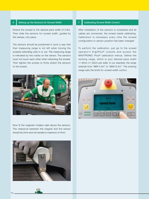
After installation of the sensors is completed and all<br />
cables are connected, the screed needs calibrating.<br />
Calibration is necessary every time the screed<br />
configuration or sensor position has been changed.<br />
To perform the calibration, just go to the screed<br />
operator’s ErgoPlus ® console and access the<br />
NAVITRONIC Plus ® calibration menue. Define the<br />
working range, which is your desired pave width<br />
+/-40cm (+/-20cm per side). In our example, the range<br />
extends from “MIN 5.4m” to “MAX 6.2m”. The working<br />
range sets the limits for screed width control.