42GR ATM Air Treatment Module - Carrier
42GR ATM Air Treatment Module - Carrier
42GR ATM Air Treatment Module - Carrier

Create successful ePaper yourself
Turn your PDF publications into a flip-book with our unique Google optimized e-Paper software.
5 - aIr treatMent ModuLe<br />
5.1 - Installation<br />
The <strong>Air</strong> <strong>Treatment</strong> <strong>Module</strong> (<strong>ATM</strong>) is generally the last<br />
component to be installed when all else is done. There are<br />
three reasons for this:<br />
• Avoidance of damage to the units while heavy work is<br />
still in progress<br />
• Releasing capital<br />
• Keeping work areas as free of clutter as possible.<br />
When the site is ready for the modules - casings are hooked<br />
onto the rails, air ducts are connected, water manifolds and<br />
shut-off valves are in place on their connection spigots,<br />
electrical installation is complete - only a few minutes are<br />
16<br />
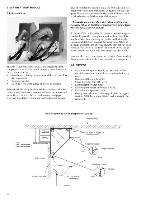
Side A<br />
Size 1: 334 mm min.<br />
Size 2: 416 mm min.<br />
False ceiling<br />
Machine room wall<br />
Supply<br />
Return<br />
Controller<br />
needed to install the module, make the hydraulic and electrical<br />
connections and connect the condensate drain. Adequate<br />
filter access and manoeuvring space will have been<br />
provided (refer to the dimensional drawings).<br />
WARNING: Do not use the water valves or pipes or the<br />
electrical cables as handles for manoeuvring the modules.<br />
They may suffer serious damage.<br />
To fix the <strong>ATM</strong> on its casing, first hook it onto the suspension<br />
hooks provided then push it against the casing. This<br />
has the effect of compressing the gasket and locking the<br />
suspension latch. Next connect the water pipes. When all<br />
modules are installed in this way open the shut-off valves on<br />
the manifolds, bleed all air from the circuits (bleed valves<br />
are on the coil water outlets) then pressurise the system.<br />
Now the electrical connections can be made. Do not switch<br />
the power on until the electrical installation is complete.<br />
5.2 - removal<br />
atM assembled on its suspension casing<br />
• Disconnect the power supply by switching off the<br />
circuit breaker which must have been installed at the<br />
outset.<br />
• Disconnect the supply cables.<br />
• Close the water shut-off valves.<br />
• Disconnect the water pipes.<br />
• Disconnect the fresh air supply if fitted.<br />
• Unlatch the suspension latch.<br />
• Gently lower the unit to disengage it from the upper<br />
section. Pull it back about 10 mm to disengage it, then<br />
remove it.<br />
Filter access<br />
door opened<br />
Concrete ceiling<br />
See details in chapter 2.7<br />
“Suspension rails”<br />
Suspension casing<br />
<strong>ATM</strong><br />
Suspension casing<br />
Latch<br />
Suspension hook<br />
Gasket