19XR (PIC II) Hermetic Centrifugal Liquid Chillers 50 Hz - Carrier
19XR (PIC II) Hermetic Centrifugal Liquid Chillers 50 Hz - Carrier
19XR (PIC II) Hermetic Centrifugal Liquid Chillers 50 Hz - Carrier

Create successful ePaper yourself
Turn your PDF publications into a flip-book with our unique Google optimized e-Paper software.
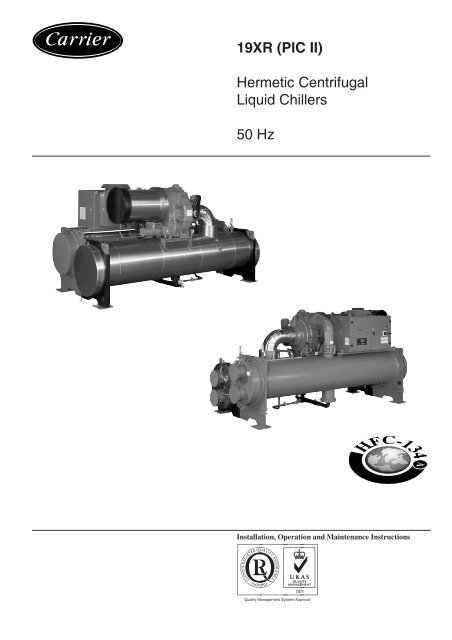
<strong>19XR</strong> (<strong>PIC</strong> <strong>II</strong>)<br />
<strong>Hermetic</strong> <strong>Centrifugal</strong><br />
<strong>Liquid</strong> <strong>Chillers</strong><br />
<strong>50</strong> <strong>Hz</strong><br />
Installation, Operation and Maintenance Instructions
The cover illustrations are for illustrative purposes only and is not part of any offer for sale or contract.<br />
2<br />
TABLE OF CONTENTS<br />
INITIAL START-UP CHECKLIST FOR <strong>19XR</strong> HERMETIC CENTRIFUGAL LIQUID CHILLERS .................................. 5<br />
1 - SAFETY CONSIDERATIONS ................................................................................................................................................... 9<br />
1.1 - Installation safety considerations ................................................................................................................................................ 9<br />
1.2 - Maintenance safety considerations ............................................................................................................................................. 9<br />
1.3 - Operating checks ......................................................................................................................................................................... 9<br />
1.4 - Equipment and components under pressure ............................................................................................................................. 10<br />
1.5 - Repair safety considerations ..................................................................................................................................................... 10<br />
2 - INTRODUCTION AND CHILLER FAMILIARIZATION................................................................................................... 11<br />
2.1 - C.E. Mark .................................................................................................................................................................................. 11<br />
2.2 - Abbreviations and explanations ................................................................................................................................................ 11<br />
2.3 - Chiller familiarization ............................................................................................................................................................... 12<br />
2.3.1 - Chiller information plate .................................................................................................................................................. 12<br />
2.3.2 - System Components ......................................................................................................................................................... 12<br />
2.3.3 - Cooler ............................................................................................................................................................................... 12<br />
2.3.4 - Condenser ......................................................................................................................................................................... 12<br />
2.3.5 - Motor-Compressor ........................................................................................................................................................... 12<br />
2.3.6 - Control Centre .................................................................................................................................................................. 12<br />
2.3.7 - Factory-Mounted Starter (Optional) ................................................................................................................................. 13<br />
2.3.8 - Storage Vessel (Optional) ................................................................................................................................................. 13<br />
2.4 - Refrigeration cycle .................................................................................................................................................................... 13<br />
2.5 - Motor/oil refrigeration cooling cycle ........................................................................................................................................ 14<br />
2.6 - Lubrication cycle....................................................................................................................................................................... 14<br />
2.6.1 - Summary .......................................................................................................................................................................... 14<br />
2.6.2 - Details ............................................................................................................................................................................... 14<br />
2.7 - Power equipment....................................................................................................................................................................... 15<br />
3 - INSTALLATION ........................................................................................................................................................................ 17<br />
3.1 - Introduction ............................................................................................................................................................................... 17<br />
3.2 - Receiving the machine .............................................................................................................................................................. 17<br />
3.2.1 - Inspect shipment ............................................................................................................................................................... 17<br />
3.2.2 - Provide machine protection .............................................................................................................................................. 17<br />
3.3 - Rigging the Machine ................................................................................................................................................................. 17<br />
3.3.1 - Rigging the complete machine ......................................................................................................................................... 17<br />
3.3.2 - Rig machine components ................................................................................................................................................. 18<br />
3.3.3 - Physical data ..................................................................................................................................................................... 19<br />
3.4 - Install machine supports............................................................................................................................................................ 25<br />
3.4.1 - Install standard isolation ................................................................................................................................................... 25<br />
3.4.2 - Installation of a levelling accessory (if necessary) ........................................................................................................... 25<br />
3.4.3 - Install spring isolation ...................................................................................................................................................... 26<br />
3.5 - Connection of water piping ....................................................................................................................................................... 26<br />
3.5.1 - Install water piping to heat exchanger.............................................................................................................................. 26<br />
3.5.2 - Install vent piping to relief devices .................................................................................................................................. 30<br />
3.6 - Make electrical connections ...................................................................................................................................................... 30<br />
3.6.1 - Installation standards and precautions.............................................................................................................................. 30<br />
3.6.2 - Electrical characteristics of the motors ............................................................................................................................ 31<br />
3.6.3 - Communication wiring ..................................................................................................................................................... 34<br />
3.6.4 - Make the necessary connections for the outgoing control signals ................................................................................... 35<br />
3.6.5 - Connect the starting cabinet ............................................................................................................................................. 35<br />
3.6.6 - Connect the starting cabinet to the control box ................................................................................................................ 37<br />
3.6.7 - <strong>Carrier</strong> Comfort Network interface (CCN) ...................................................................................................................... 37<br />
3.7 - Install Field Insulation .............................................................................................................................................................. 38
TABLE OF CONTENTS (cont'd)<br />
4 - BEFORE INITIAL START-UP................................................................................................................................................. 39<br />
4.1 - Necessary checks ...................................................................................................................................................................... 39<br />
4.1.1 - Job Data Required ............................................................................................................................................................ 39<br />
4.1.2 - Equipment Required ......................................................................................................................................................... 39<br />
4.1.3 - Using the Optional Storage Tank and Pumpout System .................................................................................................. 39<br />
4.1.4 - Remove Shipping Packaging ........................................................................................................................................... 39<br />
4.1.5 - Open Oil Circuit Valves.................................................................................................................................................... 39<br />
4.1.6 - Tighten All Gasketed Joints and Guide Vane Shaft Packing (torque depends on screw diameter) ................................. 39<br />
4.1.7 - Inspect Water Piping......................................................................................................................................................... 39<br />
4.1.8 - Check Relief Devices ....................................................................................................................................................... 40<br />
4.2 - Chiller Tightness ....................................................................................................................................................................... 40<br />
4.2.1 - Check chiller tightness ..................................................................................................................................................... 40<br />
4.2.2 - Refrigerant Tracer............................................................................................................................................................. 40<br />
4.2.3 - Leak Test Chiller .............................................................................................................................................................. 40<br />
4.3 - Standing Vacuum Test ............................................................................................................................................................... 41<br />
4.4 - Chiller Dehydration................................................................................................................................................................... 41<br />
4.5 - Inspect Wiring ........................................................................................................................................................................... 43<br />
4.6 - <strong>Carrier</strong> Comfort Network Interface (see Fig. 22) ..................................................................................................................... 43<br />
4.7 - Check Starter ............................................................................................................................................................................. 43<br />
4.8 - Oil Charge ................................................................................................................................................................................. 44<br />
4.9 - Power Up the Controls and Check the Oil Heater .................................................................................................................... 44<br />
4.10 - Check Optional Pumpout System Controls and Compressor ................................................................................................. 44<br />
4.11 - High Altitude Locations .......................................................................................................................................................... 44<br />
4.12 - Charge Refrigerant into Chiller............................................................................................................................................... 44<br />
4.13 - <strong>19XR</strong> chiller equalization without pumpout unit ................................................................................................................... 44<br />
4.14 - <strong>19XR</strong> chiller equalization with pumpout unit ......................................................................................................................... 45<br />
4.15 - Trimming refrigerant charge ................................................................................................................................................... 45<br />
5 - INITIAL START-UP .................................................................................................................................................................. 46<br />
5.1 - Preparation ................................................................................................................................................................................ 46<br />
5.2 - Dry Run to Test Start-Up Sequence .......................................................................................................................................... 46<br />
5.3 - Check Rotation .......................................................................................................................................................................... 46<br />
5.4 - Check Oil Pressure and Compressor Stop ................................................................................................................................ 46<br />
5.5 - To Prevent Accidental Start-Up ................................................................................................................................................ 46<br />
5.6 - Check Chiller Operating Condition .......................................................................................................................................... 47<br />
5.7 - Instruct the Customer Operator ................................................................................................................................................. 47<br />
6 - OPERATING INSTRUCTIONS .............................................................................................................................................. 47<br />
6.1 - Operator Duties ......................................................................................................................................................................... 47<br />
6.2 - To Start the Chiller .................................................................................................................................................................... 47<br />
6.3 - Check the Running System ....................................................................................................................................................... 47<br />
6.4 - To Stop the Chiller .................................................................................................................................................................... 48<br />
6.5 - After Limited Shutdown............................................................................................................................................................ 48<br />
6.6 - Extended Shutdown .................................................................................................................................................................. 48<br />
6.7 - After Extended Shutdown ......................................................................................................................................................... 48<br />
6.8 - Cold Weather Operation ............................................................................................................................................................ 48<br />
6.9 - Manual Guide Vane Operation .................................................................................................................................................. 48<br />
6.10 - Refrigeration Log .................................................................................................................................................................... 48<br />
7 - MAINTENANCE ....................................................................................................................................................................... <strong>50</strong><br />
7.1 - General maintenance ................................................................................................................................................................. <strong>50</strong><br />
7.2 - Soldering and welding .............................................................................................................................................................. <strong>50</strong><br />
7.1.2 - Refrigerant Properties....................................................................................................................................................... <strong>50</strong><br />
7.1.3 - Adding Refrigerant ........................................................................................................................................................... <strong>50</strong><br />
7.1.4 - Removing Refrigerant ...................................................................................................................................................... <strong>50</strong><br />
7.1.5 - Adjusting the Refrigerant Charge ..................................................................................................................................... <strong>50</strong><br />
7.1.6 - Refrigerant Leak Testing .................................................................................................................................................. <strong>50</strong><br />
7.1.7 - Checking Guide Vane Linkage ......................................................................................................................................... 51<br />
7.1.8 - Trim Refrigerant Charge .................................................................................................................................................. 51<br />
3
4<br />
TABLE OF CONTENTS (cont'd)<br />
7.2 - Weekly maintenance ................................................................................................................................................................. 51<br />
7.3 - Scheduled maintenance ............................................................................................................................................................. 52<br />
7.3.1 - Service Ontime ................................................................................................................................................................. 52<br />
7.3.2 - Inspect the Control Centre ................................................................................................................................................ 52<br />
7.3.3 - Changing Oil Filter ........................................................................................................................................................... 52<br />
7.3.4 - Oil Specification ............................................................................................................................................................... 52<br />
7.3.5 - Refrigerant Filter .............................................................................................................................................................. 53<br />
7.3.6 - Oil Reclaim Filter ............................................................................................................................................................. 53<br />
7.3.7 - Inspect Refrigerant Float System ..................................................................................................................................... 53<br />
7.3.8 - Inspect Relief Valves and Piping (see chapter 'Safety considerations') ........................................................................... 53<br />
7.3.9 - Verification of the pressure switch calibration ................................................................................................................. 53<br />
7.3.10 - Compressor Bearing and Gear Maintenance.................................................................................................................. 53<br />
7.3.11 - Inspect the Heat Exchanger Tubes ................................................................................................................................. 53<br />
7.3.12 - Water Leaks .................................................................................................................................................................... 54<br />
7.3.13 - Inspect the Starting Equipment ...................................................................................................................................... 54<br />
7.3.14 - Check Pressure Transducers ........................................................................................................................................... 54<br />
7.3.15 - Corrosion control ............................................................................................................................................................ 54<br />
LIST OF FIGURES<br />
Fig. 1 - Model number meaning ........................................................................................................................................................ 12<br />
Fig. 2 - <strong>19XR</strong> machine components .................................................................................................................................................. 12<br />
Fig. 3 - Refrigerant motor cooling and oil cooling cycles ................................................................................................................ 13<br />
Fig. 4 - Lubrication system................................................................................................................................................................ 15<br />
Fig. 5A - Starter cabinet - internal view with internal door closed ................................................................................................... 16<br />
Fig. 5B - Starter cabinet - internal view with internal door open...................................................................................................... 16<br />
Fig. 6 - Machine rigging guide .......................................................................................................................................................... 18<br />
Fig. 7 - Dimensional drawing ............................................................................................................................................................ 22<br />
Fig. 8 - Dimensional drawing - cooler, side view ............................................................................................................................. 23<br />
Fig. 9 - <strong>19XR</strong> chiller top view ........................................................................................................................................................... 23<br />
Fig. 10 - Compressor detail ............................................................................................................................................................... 24<br />
Fig. 11 - Unit rear view ..................................................................................................................................................................... 24<br />
Fig. 12 - Chiller footprint .................................................................................................................................................................. 25<br />
Fig. 13 - Standard isolation ............................................................................................................................................................... 26<br />
Fig. 14 - Accessory isolation ............................................................................................................................................................. 26<br />
Fig. 15 - <strong>19XR</strong> Accessory spring isolation........................................................................................................................................ 26<br />
Fig. 16 - Typical nozzle piping .......................................................................................................................................................... 27<br />
Fig. 17 - Nozzle arrangements - nozzle-in-head waterboxes ............................................................................................................ 28<br />
Fig. 18 - Optional pumpout system piping schematic with storage tank .......................................................................................... 29<br />
Fig. 19 - Pumpout system piping schematic with storage tank ......................................................................................................... 29<br />
Fig. 20 - Relief device locations ........................................................................................................................................................ 30<br />
Fig. 21 - COMM1 CCN communication wiring for multiple chillers (typical) ................................................................................ 34<br />
Fig. 22 - <strong>19XR</strong> with optional unit-mounted starter ........................................................................................................................... 35<br />
Fig. 23 - <strong>19XR</strong> with freestanding starter ........................................................................................................................................... 36<br />
Fig. 24 - Machine isolation................................................................................................................................................................ 38<br />
Fig. 25 - <strong>19XR</strong> leak detection procedure .......................................................................................................................................... 42<br />
Fig. 26 - Dehydration cold trap ......................................................................................................................................................... 43<br />
Fig. 27 - Rotation diagram ................................................................................................................................................................ 46<br />
Fig. 28 - Refrigeration log ................................................................................................................................................................. 48<br />
Fig. 29 - Guide vane actuator linkage ............................................................................................................................................... 51<br />
Fig. 30 - <strong>19XR</strong> float valve design ..................................................................................................................................................... 53<br />
Fig. 31 - Compressor fits and clearances .......................................................................................................................................... 55
INITIAL START-UP CHECKLIST FOR <strong>19XR</strong> HERMETIC CENTRIFUGAL LIQUID CHILLERS<br />
Name: _____________________________________________________________________________________________<br />
Address: ____________________________________________________________________________________________<br />
Town: ______________________________________________________________________________________________<br />
Country: ____________________________________________________________________________________________<br />
Post code: ___________________________________________________________________________________________<br />
Job No.: _____________________________________________________________________________________________<br />
Model: ______________________________________________________________________________________________<br />
Serial No.: ____________________________________________________________________________________________<br />
Design conditions:<br />
Evaporator<br />
Condenser<br />
Cooling Brine Flow Temperature Temperature Pressure Pass Suction Condensing<br />
capacity rate in out drop temperature temperature<br />
Compressor: Volts _______________________ RLA: _______________________ OLTA: __________________<br />
Starter: Mfg ________________________ Type: _______________________<br />
Oil pump: Volts _______________________ RLA: _______________________ OLTA: __________________<br />
Control/oil heater: 115 Volts ___________ 230 Volts ___________<br />
Refrigerant: Type _______________ Charge (kg) __________<br />
<strong>Carrier</strong> obligations:<br />
Assemble: Yes ________ No ________<br />
Leak test: Yes ________ No ________<br />
Dehydrate: Yes ________ No ________<br />
Charging: Yes ________ No ________<br />
Operating instructions: ____________ Hours<br />
START-UP TO BE PERFORMED IN ACCORDANCE WITH APPROPRIATE MACHINE START-UP INSTRUCTIONS<br />
Job data required:<br />
1. Machine installation instructions <strong>19XR</strong> Yes ________ No ________<br />
2. Machine assembly, wiring and piping diagrams Yes ________ No ________<br />
3. Starting equipment details and wiring diagrams Yes ________ No ________<br />
4. Applicable design data (see above) Yes ________ No ________<br />
5. Diagrams and instructions for special controls Yes ________ No ________<br />
Initial machine pressure: __________________<br />
Was machine tight? Yes ________ No ________<br />
If not, were leaks corrected? Yes ________ No ________<br />
Was machine dehydrated after repairs? Yes ________ No ________<br />
Check oil level and record:<br />
Add oil: Yes ________ No ________<br />
Amount: ___________________________<br />
_______ 3/4 _______ 3/4<br />
_______ 1/2 Top sight glass _______ 1/2 Bottom sight glass<br />
_______ 1/4 _______ 1/4<br />
Record pressure drops:<br />
Evaporator ________________ Condenser ________________<br />
Refrigerant charge:<br />
Initial charge _______________ Final charge after trim ______________<br />
5
INSPECT WIRING AND RECORD ELECTRICAL DATA:<br />
Ratings:<br />
Motor voltage: ________ Motor(s) amps: ________ Oil pump voltage: ________ Starter amps: ________<br />
Line voltages: Motor: _____________ Oil pump: _____________ Controls/oil heater: ____________<br />
Field-installed starters only:<br />
Check continuity T1 to T1, etc (motor to starter power wiring).<br />
Megger starter: Do not megger a motor connected to a solid-state starter, unless the leads to the motor are disconnected and<br />
meggered.<br />
Megger motor Phase to phase Phase to ground<br />
T1-T2 T1-T3 T2-T3 T1-G T2-G T3-G<br />
10-second readings<br />
60-second readings<br />
Polarization ratio<br />
Starter:<br />
Electro-mechanical __________ Electronic __________<br />
Motor load current transformer ratio _____ : _____ Signal resistor size ________ Ohms<br />
Transition timer time __________ seconds<br />
Check magnetic overloads: Add dash pot oil Yes _______ No _______<br />
Solid-state overloadsYes _______ No _______<br />
Solid-state starter: Initial voltage __________ Volts Ramp setting __________ seconds<br />
Controls: safety, operating, etc<br />
Perform controls test Yes _______ No _______<br />
CAUTION: Compressor motor and control centre must be properly and individually connected back to the earth ground in the<br />
starter (in accordance with certified drawings). Yes _______<br />
Run machine:<br />
Do these safeties shut down the machine?<br />
Condenser water flow switch: Yes ________ No ________<br />
Chilled water flow switch: Yes ________ No ________<br />
Pump interlocks: Yes ________ No ________<br />
Initial start:<br />
Line up all valves in accordance with instruction manual: _______ Start water pumps and establish water flow: ________<br />
Oil level and temperature correct: ________ Check oil pump rotation pressure ________<br />
Check compressor motor rotation (motor end sight glass) and record: Clockwise ________<br />
Restart compressor. Bring up to speed. Shut down. Any abnormal coastdown noise?: Yes* ________ No ________<br />
* If yes, determine cause<br />
Start machine and operate. Complete the following:<br />
A. Trim charge and record.<br />
B. Complete any remaining control calibration and record.<br />
C. Take at least 2 sets of operational log readings and record.<br />
D. After machine has been successfully run and set up, shut down and mark shutdown oil and refrigerant levels.<br />
E. Give operating instructions to owner's operating personnel. Hours given: ________ hrs<br />
F. Call your <strong>Carrier</strong> factory representative to report chiller start-up.<br />
Signature: ______________________________________ Date: _________<br />
(<strong>Carrier</strong> technician)<br />
Signature: ______________________________________ Date: _________<br />
(Customer representative)<br />
6
<strong>19XR</strong> HERMETIC CENTRIFUGAL LIQUID CHILLER CONFIGURATION SETTINGS LOG<br />
(Remove and use for job file)<br />
Controller name: Bus No.:<br />
Element No.<br />
Table description: Table name: SETPOINT<br />
Setpoint table configuration sheet <strong>19XR</strong><br />
Description Range Units Default Value<br />
Base demand limit 40 to 100 % 100<br />
LCW setpoint 12.2 to 48.9 °C <strong>50</strong><br />
ECW setpoint 12.2 to 48.9 °C 60<br />
Controller name: Bus No.:<br />
Element No.<br />
Table description: Table name: OCCP01S<br />
Local mode time schedule configuration sheet - <strong>19XR</strong> <strong>PIC</strong> <strong>II</strong> control - OCCP01S<br />
Day Occupied time Unoccupied time<br />
M T W T F Sa Su H<br />
Period 1<br />
Period 2<br />
Period 3<br />
Period 4<br />
Period 5<br />
Period 6<br />
Period 7<br />
Period 8<br />
Note: Default setting is occupied 24 hours/day<br />
Controller name: Bus No.:<br />
Element No.<br />
Table description: Table name: HOLIDEFS<br />
Holiday configuration sheet<br />
Description Range Units Value<br />
Holiday start month 1-12<br />
Holiday start day 1-31<br />
Duration 0-99 Days<br />
7
Table description: Table name: HOLIDEFS<br />
Holiday configuration sheet<br />
Description Range Units Value<br />
Holiday start month 1-12<br />
Holiday start day 1-31<br />
Duration 0-99 Days<br />
Table description: Table name: HOLIDEFS<br />
Holiday configuration sheet<br />
Description Range Units Value<br />
Holiday start month 1-12<br />
Holiday start day 1-31<br />
Duration 0-99 Days<br />
8
1 - SAFETY CONSIDERATIONS<br />
<strong>19XR</strong> liquid chillers are designed to provide safe and reliable<br />
service when operated within design specifications. When<br />
operating this equipment, use good judgment and safety<br />
precautions to avoid damage to equipment and property or<br />
injury to personnel.<br />
Be sure you understand and follow the procedures and safety<br />
precautions contained in the machine instructions as well as<br />
those listed in this guide.<br />
1.1 - Installation safety considerations<br />
In certain cases the safety stops are installed on ball valves.<br />
These valves are factory-supplied lead-sealed in the open<br />
position. This system permits isolating and removing the<br />
safety stop for checking and replacing. The safety stops are<br />
designed and installed to ensure protection against fire risk.<br />
Removing the safety stops is only permitted if the fire risk is<br />
fully controlled and the responsibility of the user.<br />
All factory-installed safety valves are lead-sealed to prevent<br />
any calibration change. If a safety stop is removed for<br />
checking or replacement please ensure that there is always an<br />
active safety stop on each of the reversing valves installed in<br />
the unit.<br />
The safety valves must be connected to discharge pipes. These<br />
pipes must be installed in a way that ensures that people and<br />
property are not exposed to refrigerant leaks. These fluids<br />
may be diffused in the air, but far away from any building air<br />
intake, or they must be discharged in a quantity that is<br />
appropriate for a suitably absorbing environment.<br />
Periodic check of the safety valves: See paragraph<br />
“Maintenance safety considerations”.<br />
DANGER:<br />
DO NOT VENT refrigerant relief valves within a building.<br />
Outlet from relief valve must be vented outdoors. The accumulation<br />
of refrigerant in an enclosed space can displace oxygen<br />
and cause asphyxiation.<br />
PROVIDE adequate ventilation, especially for enclosed and<br />
low overhead spaces. Inhalation of high concentrations of<br />
vapour is harmful and may cause heart irregularities, unconsciousness,<br />
or death. Misuse can be fatal. Vapour is heavier<br />
than air and reduces the amount of oxygen available for<br />
breathing. Product causes eye and skin irritation.<br />
Decomposition products are hazardous.<br />
DO NOT USE OXYGEN to purge lines or to pressurize a<br />
machine for any purpose. Oxygen gas reacts violently with oil,<br />
grease, and other common substances.<br />
NEVER EXCEED specified test pressures, VERIFY the allowable<br />
test pressure by checking the instruction literature and<br />
the design pressures on the equipment nameplate.<br />
DO NOT USE air for leak testing. Use only refrigerant or dry<br />
nitrogen.<br />
DO NOT VALVE OFF any safety device.<br />
BE SURE that all pressure relief devices are properly<br />
installed before operating any machine.<br />
1.2 - Maintenance safety considerations<br />
Engineers working on the electric or refrigeration components<br />
must be authorized, trained and fully qualified to do so.<br />
All refrigerant circuit repairs must be carried out by a trained<br />
person, fully qualified to work on these units. He must have<br />
been trained and be familiar with the equipment and the<br />
installation. All welding operations must be carried out by<br />
qualified specialists.<br />
Any manipulation (opening or closing) of a shut-off valve<br />
must be carried out by a qualified and authorised engineer.<br />
These procedures must be carried out with the unit shut-down.<br />
NOTE: The unit must never be left shut down with the liquid<br />
line valve closed, as liquid refrigerant can be trapped between<br />
this valve and the expansion device. (This valve is situated on<br />
the liquid line before the filter drier box.)<br />
During any handling, maintenance and service operations the<br />
engineers working on the unit must be equipped with safety<br />
gloves, glasses, shoes and protective clothing.<br />
WARNING:<br />
DO NOT WELD OR FLAMECUT any refrigerant line or<br />
vessel until all refrigerant (liquid and vapour) has been<br />
removed from chiller. Traces of vapour should be displaced<br />
with dry air nitrogen and the work area should be well<br />
ventilated. Refrigerant in contact with an open flame produces<br />
toxic gases.<br />
DO NOT work on high-voltage equipment unless you are a<br />
qualified electrician.<br />
DO NOT WORK ON electrical components, including control<br />
panels, switches, relays etc, until you are sure ALL POWER<br />
IS OFF; residual voltage can leak from capacitors or solid<br />
state components.<br />
LOCK OPEN AND TAG electrical circuits during servicing.<br />
IF WORK IS INTERRUPTED, confirm that all circuits are<br />
de-energized before resuming work.<br />
1.3 - Operating checks<br />
During the life-time of the system, inspection and tests must<br />
be carried out in accordance with national regulations.<br />
The information on operating inspections given in annex C of<br />
standard EN378-2 can be used if no similar criteria exist in<br />
the national regulations.<br />
Safety device checks (annex C6 – EN378-2): The safety<br />
devices must be checked on site once a year for safety devices<br />
(high-pressure switches), and every five years for external<br />
overpressure devices (safety globe valves).<br />
9
If the machine operates in a corrosive environment, inspect<br />
the protection devices more frequently.<br />
DO NOT ATTEMPT TO REPAIR OR RECONDITION any<br />
safety devices when corrosion or build-up of foreign material<br />
(rust, dirt, scale, etc.) is found within the valve body or<br />
mechanism. If necessary, replace the device.<br />
DO NOT install safety valves in series or backwards.<br />
PROVIDE A DRAIN connection in the vent line near each<br />
pressure relief device to prevent a build-up of condensate or<br />
rain water.<br />
1.4 - Equipment and components under pressure<br />
These products incorporate equipment or components under<br />
pressure, manufactured by <strong>Carrier</strong> or other manufacturers. We<br />
recommend that you consult your appropriate national trade<br />
association or the owner of the equipment or components under<br />
pressure (declaration, re-qualification, retesting, etc.). The<br />
characteristics of this equipment/these components are given<br />
on the nameplate or in the required documentation, supplied<br />
with the products.<br />
1.5 - Repair safety considerations<br />
All installation parts must be maintained by the personnel in<br />
charge, in order to avoid material deterioration and injuries to<br />
people. Faults and leaks must be repaired immediately. The<br />
authorized technician must have the responsibility to repair the<br />
fault immediately. Each time repairs have been carried out to<br />
the unit, the operation of the safety devices must be re-checked.<br />
If a leak occurs or if the refrigerant becomes polluted (e.g. by a<br />
short circuit in a motor) remove the complete charge using a<br />
recovery unit and store the refrigerant in mobile containers.<br />
Repair the leak detected and recharge the circuit with the total<br />
R134a charge, as indicated on the unit name plate.<br />
DO NOT siphon refrigerant.<br />
AVOID SPILLING liquid refrigerant on skin or getting it<br />
into the eyes. USE SAFETY GOGGLES AND SAFETY<br />
GLOVES. Wash any spills from the skin with soap and water.<br />
If liquid refrigerant enters the eyes, IMMEDIATELY FLUSH<br />
EYES with water and consult a physician.<br />
NEVER APPLY an open flame or live steam to refrigerant<br />
cylinder. Dangerous overpressure can result. If it is necessary<br />
to heat refrigerant, use only warm water.<br />
DO NOT REUSE disposable (non-returnable) cylinders or<br />
attempt to refill them. It is DANGEROUS AND ILLEGAL.<br />
When cylinders are emptied, evacuate remaining gas pressure,<br />
loosen the collar and unscrew and discard the valve stem. DO<br />
NOT INCINERATE.<br />
During refrigerant operations, CHECK THE REFRIGERANT<br />
TYPE before adding refrigerant to the machine. The introduction<br />
of the wrong refrigerant can cause damage or malfunction<br />
to this machine.<br />
10<br />
ATTENTION: No part of the unit must use feet, racks or<br />
supports during operation. Periodically monitor and repair or<br />
if necessary replace any component or piping that shows<br />
signs of damage.<br />
DO NOT climb over a machine. Use platform, or staging.<br />
USE MECHANICAL EQUIPMENT (crane, hoist, etc.) to lift<br />
or move heavy components. Even if components are light, use<br />
mechanical equipment when there is a risk of slipping or losing<br />
your balance.<br />
DO NOT USE eyelets to lift any part of the machine or the<br />
complete machine.<br />
BE AWARE that certain automatic start arrangements CAN<br />
ENGAGE TOWER FAN, OR PUMPS. Open the disconnect<br />
ahead of the tower fans, or pumps.<br />
USE only repair or replacement parts that meet the code<br />
requirements of the original equipment.<br />
DO NOT VENT OR DRAIN water boxes containing industrial<br />
brines, without the permission of your process control group.<br />
DO NOT LOOSEN water box bolts until the water box has<br />
been completely drained.<br />
DO NOT LOOSEN a packing gland nut before checking that<br />
the nut has a positive thread engagement.<br />
PERIODICALLY INSPECT all valves, fittings, and piping<br />
for corrosion, rust, leaks, or damage.<br />
During refrigerant removal and storage operations follow applicable<br />
regulations. These regulations, permitting conditioning and<br />
recovery of halogenated hydrocarbons under optimum quality<br />
conditions for the products and optimum safety conditions for<br />
people, property and the environment are described in standard<br />
NFE 29795.<br />
Any refrigerant transfer and recovery operations must be carried<br />
out using a transfer unit. A 3/8” SAE connector on the manual<br />
liquid line valve is supplied with all units for connection to the<br />
transfer station. The units must never be modified to add refrigerant<br />
and oil charging, removal and purging devices. All these<br />
devices are provided with the units. Please refer to the certified<br />
dimensional drawings for the units.
2 - INTRODUCTION AND CHILLER FAMILIARIZATION<br />
Prior to initial start-up of the <strong>19XR</strong> unit, those involved in the<br />
start-up, operation, and maintenance should be thoroughly<br />
familiar with these instructions and other necessary job data. This<br />
book is outlined so that you may become familiar with the control<br />
system before performing start-up procedures. Procedures<br />
in this manual are arranged in the sequence required for proper<br />
chiller start-up and operation.<br />
Maximum outside temperature:<br />
For transport and storage of the <strong>19XR</strong> units the minimum and<br />
maximum allowable temperatures are –20°C and +48°C.<br />
Unit operating range<br />
Evaporator <strong>19XR</strong> Minimum Maximum<br />
Evaporator entering water temperature* °C 6 17<br />
Evaporator leaving water temperature* °C 3.3 10<br />
Condenser (water-cooled) <strong>19XR</strong> Minimum Maximum<br />
Condenser entering water temperature* °C 16 35<br />
Condenser leaving water temperature* °C 13.3 44<br />
* For application requiring brine operation, contact <strong>Carrier</strong> s.a. for unit selection<br />
using the <strong>Carrier</strong> electronic catalog.<br />
WARNING: This unit uses a microprocessor control system.<br />
Do not short or jumper between terminations on circuit<br />
boards or modules; control or board failure may result.<br />
Be aware of electrostatic discharge (static electricity) when<br />
handling or making contact with circuit boards or module<br />
connections. Always touch a chassis (grounded) part to<br />
dissipate body electrostatic charge before working inside control<br />
centre.<br />
Use extreme care when handling tools near boards and when<br />
connecting or disconnecting terminal plugs. Circuit boards<br />
can easily be damaged. Always hold boards by the edges and<br />
avoid touching components and connections.<br />
This equipment uses, and can radiate, radio frequency energy.<br />
If not installed and used in accordance with the instruction<br />
manual, it may cause interference to radio communications. It<br />
has been tested and found to comply with European Directive<br />
89/336/EEC, on Electromagnetic Compatibility. Operation of<br />
this equipment in a residential area is likely to cause interference,<br />
in which case the user, at his own expense, will be<br />
required to take whatever measures may be required to correct<br />
the interference. Always store and transport replacement or<br />
defective boards in anti-static shipping bag.<br />
2.1 - C.E. Mark<br />
Compliance with European Directives<br />
All <strong>19XR</strong> machines carry the CE mark, which is mandatory for<br />
their sale within the EU. The declaration supplied with the<br />
machines specifies the regulations to which they are subject:<br />
73/23/EEC Low voltage<br />
89/336/EEC Electromagnetic compatibility (EMC)*<br />
and if the machine is supplied complete (with starter and relief<br />
valves): 89/392/EEC Machinery safety<br />
Therefore, units will be delivered with the following<br />
certificates:<br />
With starter Without starter or relief<br />
valve<br />
Low voltage Conformity Conformity<br />
EMC Conformity Conformity<br />
Machinery safety Conformity Incorporation<br />
* The generic standards enabling compliance with the requirements of the EMC<br />
directives for an industrial environment are as follows:<br />
EN <strong>50</strong>082-2 for immunity<br />
EN <strong>50</strong>081-2 for emissions<br />
2.2 - Abbreviations and explanations<br />
Frequently used abbreviations in this manual include:<br />
CCM - Chiller Control Module<br />
CCN - <strong>Carrier</strong> Comfort Network<br />
CCW - Counterclockwise<br />
CVC - Chiller Visual Control<br />
CW - Clockwise<br />
ECW - Entering Chilled Water<br />
ECDW - Entering Condenser Water<br />
EMS - Energy Management System<br />
HGBP - Hot Gas Bypass<br />
I/O - Input/Output<br />
ISM - Integrated Starter Module<br />
LCD - <strong>Liquid</strong> Crystal Display<br />
LCDW - Leaving Condenser Water<br />
LCW - Leaving Chilled Water<br />
LED - Light-Emitting Diode<br />
OLTA - Overload Trip Amps<br />
<strong>PIC</strong> <strong>II</strong> - Product Integrated Control <strong>II</strong><br />
RLA - Rated Load Amps<br />
SI - International System of Units<br />
TXV - Thermostatic Expansion Valve<br />
The CVC software version number of your <strong>19XR</strong> unit will be<br />
located on the CVC module.<br />
Information on the unit control is not included in this manual.<br />
Refer to separate control manual.<br />
11
2.3 - Chiller familiarization<br />
2.3.1 - Chiller information plate<br />
The information plate is located below the control box.<br />
12<br />
Chronological number<br />
<strong>19XR</strong> 41 43 CP 362 S EE<br />
Model description Exchanger code<br />
<strong>Hermetic</strong> centrifugal<br />
liquid chiller<br />
EE - SDM<br />
A - TUV<br />
B - ISPESL<br />
D - SA<br />
S: standard efficiency<br />
H: high efficiency<br />
Motor size<br />
Evaporator size Condenser size<br />
Compressor type<br />
Fig. 1 - Model number meaning<br />
2.3.2 - System Components<br />
The components include the cooler and condenser heat exchangers<br />
in separate vessels, motor-compressor, lubrication package,<br />
control centre, and motor starter. All connections from pressure<br />
vessels have external threads to enable each component to be<br />
pressure tested with a threaded pipe cap during factory assembly.<br />
14<br />
13 12<br />
11<br />
10<br />
3<br />
9<br />
1 2<br />
1. Guide vane actuator<br />
2. Suction elbow<br />
3. Compressor<br />
4. Cooler, auto reset relief valve*<br />
5. Cooler pressure transducer<br />
6. Condenser in/out temperature thermistors<br />
7. Cooler in/out temperature thermistors<br />
8. Machine identification nameplate (situated on the starter cabinet side) - see<br />
right-hand figure 'Rear view'<br />
9. Refrigerant charging valve<br />
10. Typical flange connections<br />
11. Oil drain valve<br />
12. Oil level sight glass<br />
13. Refrigerant oil cooler (hidden)<br />
14. Branch circuit control box<br />
* One relief valve is standard. Dual relief valves as an option<br />
4<br />
5<br />
7<br />
6<br />
Fig. 2 - <strong>19XR</strong> machine components<br />
2.3.3 - Cooler<br />
This vessel (also known as the evaporator) is located underneath<br />
the compressor. The cooler is maintained at lower temperature/<br />
pressure so that evaporating refrigerant can remove heat from<br />
water flowing through its internal tubes.<br />
2.3.4 - Condenser<br />
The condenser operates at a higher temperature/pressure than<br />
the cooler and has water flowing through its internal tubes in<br />
order to remove heat from the refrigerant.<br />
2.3.5 - Motor-Compressor<br />
This component maintains system temperature/pressure<br />
differences and moves the heat carrying refrigerant from the<br />
cooler to the condenser.<br />
2.3.6 - Control Centre<br />
The control centre is the user interface for controlling the<br />
chiller. It regulates the chiller’s capacity as required to maintain<br />
proper leaving chilled water temperature.<br />
Front view Rear view<br />
31<br />
32<br />
30<br />
15. Condenser auto reset relief valves*<br />
16. Circuit breaker<br />
17. CVC<br />
18. Unit-mounted starter (optional)<br />
19. Motor sight glass<br />
20. Cooler return-end waterbox cover<br />
21. Cooler nameplate<br />
22. Condenser nameplate<br />
23. Typical waterbox drain port<br />
24. Condenser return-end waterbox cover<br />
25. Refrigerant moisture/flow indicator<br />
26. Refrigerant filter/drier<br />
27. <strong>Liquid</strong> line isolation valve (optional)<br />
28. Linear float valve chamber<br />
29. Vessel take-apart connector<br />
30. Discharge isolation valve (optional)<br />
31. Pumpout valve<br />
32. Condenser pressure transducer<br />
15<br />
8<br />
18 19<br />
29 28 27 26 25 24 23 22<br />
17<br />
16<br />
20<br />
21
The control centre:<br />
registers cooler, condenser, and lubricating system pressures<br />
shows chiller operating condition and alarm shutdown<br />
conditions<br />
records the total chiller operating hours<br />
sequences chiller start, stop, and recycle under microprocessor<br />
control<br />
provides access to other CCN (<strong>Carrier</strong> Comfort Network)<br />
devices<br />
2.3.7 - Factory-Mounted Starter (Optional)<br />
The starter allows for the proper start and disconnect of electrical<br />
energy for the compressor-motor, oil pump, oil heater,<br />
and control panels.<br />
2.3.8 Storage Vessel (Optional)<br />
There are 2 sizes of storage vessels available. The vessels have<br />
relief valves, a drain valve and a male flare vapour connection<br />
for the pumpout unit.<br />
NOTE: If a storage vessel is not used at the jobsite, factoryinstalled<br />
isolation valves on the chiller may be used to isolate<br />
the chiller charge in either the cooler or condenser. An optional<br />
pump-out system is used to transfer refrigerant from vessel to<br />
vessel.<br />
1. FLASC chamber<br />
2. Condenser water<br />
3. Condenser<br />
4. Condenser isolation valve<br />
5. Transmission<br />
6. Diffuser<br />
7. Guide vane motor<br />
8. Motor<br />
9. Guide vanes<br />
10. Impeller<br />
11. Compressor<br />
12. Back pressure orifice<br />
13. Oil cooling<br />
14. Oil filter<br />
15. Oil pump<br />
16. Stator<br />
17. Rotor<br />
18. Refrigerant cooling isolation valve<br />
19. Float valve chamber<br />
20. Filter drier<br />
2.4 - Refrigeration cycle<br />
The compressor continuously draws refrigerant vapour from<br />
the cooler at a rate set by the amount of guide vane opening.<br />
As the compressor suction reduces the pressure in the cooler,<br />
the remain-ing refrigerant boils at a fairly low temperature<br />
(typically 3 to 6°C). The energy required for boiling is obtained<br />
from the water flowing through the cooler tubes. With heat<br />
energy removed, the water becomes cold enough for use in an<br />
air conditioning circuit or process liquid cooling.<br />
After taking heat from the water, the refrigerant vapour is compressed.<br />
Compression adds still more heat energy, and the refrigerant<br />
is quite warm (typically 37 to 40°C) when it is discharged<br />
from the compressor into the condenser.<br />
Relatively cool (typically 18 to 32°C) water flowing into the<br />
condenser tubes removes heat from the refrigerant and the<br />
vapour condenses to liquid.<br />
Fig. 3 - Refrigerant motor cooling and oil cooling cycles<br />
The liquid refrigerant passes through orifices into the FLASC<br />
(Flash Subcooler) chamber (Fig. 3). Since the FLASC chamber<br />
is at a lower pressure, part of the liquid refrigerant flashes to<br />
vapour, thereby cooling the remaining liquid. The FLASC vapour<br />
21. Orificed fitting<br />
22. Moisture/flow indicator<br />
23. Orificed fitting<br />
24. Thermostatic expansion valves (TXV)<br />
25. Distribution pipe<br />
26. Cooler isolation valve<br />
27. Evaporator<br />
28. Chilled water<br />
29. Refrigerant liquid<br />
30. Refrigerant vapour<br />
31. Refrigerant liquid/vapour<br />
13
is recondensed on the tubes which are cooled by entering condenser<br />
water. The liquid drains into a float chamber between the<br />
FLASC chamber and cooler. Here a float valve forms a liquid<br />
seal to keep FLASC chamber vapour from entering the cooler.<br />
When liquid refrigerant passes through the valve, some of it flashes<br />
to vapour in the reduced pressure on the cooler side. In flashing,<br />
it removes heat from the remaining liquid. The refrigerant is<br />
now at a temperature and pressure at which the cycle began.<br />
2.5 - Motor/oil refrigeration cooling cycle<br />
The motor and the lubricating oil are cooled by liquid refrigerant<br />
taken from the bottom of the condenser vessel (Fig. 3). Flow of<br />
refrigerant is maintained by the pressure differential that exists<br />
due to compressor operation. After the refrigerant flows past an<br />
isolation valve, an in-line filter, and a sight glass/moisture indicator,<br />
the flow is split between motor cooling and oil cooling<br />
systems.<br />
Flow to the motor flows through an orifice and into the motor.<br />
Once past the orifice, the refrigerant is directed over the motor<br />
by a spray nozzle. The refrigerant collects in the bottom of the<br />
motor casing and then is drained back into the cooler through<br />
the motor refrigerant drain line. A back pressure valve or an<br />
orifice in this line maintains a higher pressure in the motor<br />
shell than in the cooler/oil sump. The motor is protected by a<br />
temperature sensor imbedded in the stator windings. A further<br />
increase in motor winding temperature past the motor override<br />
set point will override the temperature capacity control to hold,<br />
and if the motor temperature rises 5.5 K above this set point,<br />
will close the inlet guide vanes. If the temperature rises above<br />
the safety limit, the compressor will shut down.<br />
Refrigerant that flows to the oil cooling system is regulated by<br />
thermostatic expansion valves (TXVs). The TXVs regulate flow<br />
into the oil/refrigerant plate and frame-type heat exchanger. The<br />
expansion valve bulbs control oil temperature to the bearings.<br />
The refrigerant leaving the heat exchanger then returns to the<br />
cooler.<br />
2.6 - Lubrication cycle<br />
2.6.1 - Summary<br />
The oil pump, oil filter, and oil cooler make up a package located<br />
partially in the transmission casting of the compressor-motor<br />
assembly. The oil is pumped into a filter assembly to remove<br />
foreign particles and is then forced into an oil cooler heat exchanger<br />
where the oil is cooled to proper operational temperatures.<br />
After the oil cooler, part of the flow is directed to the gears and<br />
the high speed shaft bearings; the remaining flow is directed to<br />
the motor shaft bearings. Oil drains into the transmission oil<br />
sump to com-plete the cycle (Fig. 4).<br />
2.6.2 - Details<br />
Oil is charged into the lubrication system through a hand valve.<br />
Two sight glasses in the oil reservoir permit oil level observation.<br />
Normal oil level is between the middle of the upper sight glass<br />
and the top of the lower sight glass when the compressor is<br />
shut down. The oil level should be visible in at least one of the<br />
2 sight glasses during operation.<br />
Oil sump temperature is displayed on the CVC default screen.<br />
Oil sump temperature ranges during compressor operation<br />
between 52 to 66°C.<br />
14<br />
The oil pump suction is fed from the oil reservoir. An oil pressure<br />
relief valve maintains 124 to 172 kPa differential pressure in<br />
the system at the pump discharge. This differential pressure<br />
can be read directly from the CVC default screen.<br />
The oil pump discharges oil to the oil filter assembly. This filter<br />
can be closed to permit removal of the filter without draining<br />
the entire oil system. The oil is then piped to the oil cooler.<br />
This heat exchanger uses refrigerant from the condenser as the<br />
coolant. The refrigerant cools the oil to a temperature between<br />
49 and 60°C.<br />
As the oil leaves the oil cooler, it passes the oil pressure transducer<br />
and the thermal bulb for the refrigerant expansion valve on the<br />
oil cooler. The oil is then divided, with a portion flowing to the<br />
thrust bearing, forward pinion bearing, and gear spray. The<br />
balance then lubricates the motor shaft bearings and the rear<br />
pinion bearing. The oil temperature is measured as the oil leaves<br />
the thrust and forward journal bearings within the bearing<br />
housing. The oil then drains into the oil reservoir at the base of<br />
the compressor. The <strong>PIC</strong> <strong>II</strong> (Product Integrated Control)<br />
measures the temperature of the oil in the sump and maintains<br />
the temperature during shut-down. This temperature is read on<br />
the CVC default screen.<br />
During the chiller start-up, the <strong>PIC</strong> <strong>II</strong> will energize the oil pump<br />
and provide 15 seconds of prelubrication to the bearings after<br />
pressure is verified before starting the compressor. During shut<br />
down, the oil pump will run for 60 seconds to post-lubricate<br />
after the compressor shuts down. The oil pump can also be<br />
energized for testing purposes in the Control Test.<br />
Ramp loading can slow the rate of guide vane opening to<br />
minimize oil foaming at start-up. If the guide vanes open quickly,<br />
the sudden drop in suction pressure can cause any refrigerant<br />
in the oil to flash. The resulting oil foam cannot be pumped<br />
efficiently; therefore, oil pressure falls off and lubrication is<br />
poor. If oil pressure falls below 103 kPa differential, the <strong>PIC</strong> <strong>II</strong><br />
will shut down the compressor.<br />
If the controls are subject to a power failure that lasts more than 3<br />
hours, the oil pump will be energized periodically when the<br />
power is restored. This helps to eliminate refrigerant that has<br />
migrated to the oil sump during the power failure. The controls<br />
will energize the pump for 60 seconds every 30 minutes until<br />
the chiller is started.<br />
Oil Reclaim System<br />
The oil reclaim system returns oil lost from the compressor<br />
housing back to the oil reservoir by recovering the oil from 2<br />
areas on the chiller. The guide vane housing is the primary area<br />
of recovery. Oil is also recovered by skimming it from the<br />
operating refrigerant level in the cooler vessel.<br />
Primary oil recovery mode<br />
Oil is normally recovered through the guide vane housing on<br />
the chiller. This is possible because oil is normally entrained<br />
with the refrigerant in the chiller. As the compressor pulls the<br />
refrigerant up from the cooler into the guide vane housing to<br />
be compressed, the oil normally drops out at this point and falls<br />
to the bottom of the guide vane housing where it accumulates.<br />
Using discharge gas pressure to power an eductor, the oil is<br />
drawn from the housing and is discharged into the oil reservoir.
1. Rear motor bearing<br />
2. Forward motor bearing<br />
3. Labyrinth gas line<br />
4. Oil supply to forward high speed bearing<br />
5. Isolation valve<br />
6. Filter<br />
7. Sight glass<br />
8. Isolation valve<br />
9. Check valve<br />
10. Filter<br />
11. Eductor<br />
12. Oil heater<br />
Secondary oil recovery method<br />
The secondary method of oil recovery is significant under light<br />
load conditions, when the refrigerant going up to the compressor<br />
suction does not have enough velocity to bring oil along with it.<br />
Under these conditions, oil normally collects in a greater concentration<br />
at the top level of the refrigerant in the cooler. This<br />
oil and refrigerant mixture is skimmed from the side of the<br />
cooler and is then drawn up to the guide vane housing. There is<br />
a filter in this line. Because the guide vane housing pressure is<br />
much lower than the cooler pressure, the refrigerant boils off,<br />
leaving the oil behind to be collected by the primary oil recovery<br />
method.<br />
Fig. 4 - Lubrication system<br />
2.7 - Power equipment<br />
13. Oil pump<br />
14. Oil motor<br />
15. Oil cooler<br />
16. Isolation valve<br />
17. Pressure transducer<br />
18. TXV bulb<br />
19. Motor cooling line<br />
The <strong>19XR</strong> requires a starter cabinet to control a hermetic<br />
turbo-compressor motor, the oil pump and various auxiliary<br />
units. This cabinet serves as a user interface. Only one type of<br />
cabinet is currently available from <strong>Carrier</strong> SA: electronic starting<br />
(see specification Z375 and EE038 for specific requirements<br />
for the starter cabinet). All cabinets must comply with these<br />
specifications with the aim of achieving correct compressor<br />
starting and satisfying the mechanical safety requirements.<br />
The cabinets may be supplied separately from the units, and<br />
either function on a remote basis or are mounted directly on the<br />
unit (optional for low voltages only).<br />
15
Factory-mounted electronic starter (optional) - see Figures<br />
5A and 5B<br />
NOTE: The main circuit breaker QF101* on the front of the<br />
starter disconnects all circuits.<br />
Circuit breaker QF66* supplies power to the control centre, the<br />
oil heater and the compressor starter control circuit. Circuit<br />
breaker QF4* supplies power to the oil pump. Circuit breaker<br />
QF11* supplies power to the control circuit. All three circuit<br />
breakers are connected downstream of QF101* so that they do<br />
not remain energized if the QF101* disconnect is in the “off”<br />
position.<br />
16<br />
4<br />
7<br />
1<br />
8 3<br />
7<br />
6<br />
5<br />
Fig. 5A - Starter cabinet - internal view with internal<br />
door closed<br />
1. ISM module<br />
2. Circuit breaker<br />
3. CCM module<br />
4. CVC module<br />
5. Electronic starter<br />
6. Contactor<br />
7. Door closed (Fig. 5A above) or open (Fig. 5B opposite)<br />
8. Conductor for field connection<br />
4<br />
The starter cabinet includes:<br />
The electronic starter that provides on/off phase control as its<br />
primary function, also reduces starting torque and motor inrush<br />
current, thus reducing mechanical stress and increasing the<br />
useful life of the motor.<br />
The ISM module controls the motor start-up, the control<br />
section and the <strong>PIC</strong> <strong>II</strong> control.<br />
* For more details refer to the wiring diagram supplied with<br />
the unit.<br />
2<br />
8<br />
Fig. 5B - Starter cabinet - internal view with internal<br />
door open<br />
2
3 - INSTALLATION<br />
3.1 - Introduction<br />
The <strong>19XR</strong> machine is factory assembled, wired, leak tested<br />
and electrically tested. Installation (not by <strong>Carrier</strong>) consists<br />
primarily of establishing water and electrical services to the<br />
machine. The rigging, installation, field wiring, field piping,<br />
and insulation of waterbox covers are the responsibilty of the<br />
contractor and/or customer. <strong>Carrier</strong> has no installation<br />
responsibilities for the equipment.<br />
3.2 - Receiving the machine<br />
3.2.1 - Inspect shipment<br />
CAUTION: Do not open any valves or loosen any connections.<br />
The standard <strong>19XR</strong> machine is shipped with a full refrigerant<br />
charge. Some machines may be shipped with a nitrogen holding<br />
charge as an option.<br />
Inspect for shipping damage while machine is still on<br />
shipping conveyance. If machine appears to be damaged or has<br />
been torn loose from its anchorage, have it examined by<br />
transportation inspectors before removal. Forward claim<br />
papers directly to transportation company. Manufacturer is<br />
not responsible for any damage incurred in transit.<br />
Confirm that the unit received is the one ordered. Compare<br />
the name plate data with the order.<br />
The unit name plate must include the following<br />
information:<br />
- Version number<br />
- Model number<br />
- CE marking<br />
- Serial number<br />
- Year of manufacture and test date<br />
- Refrigerant used and refrigerant class<br />
- Refrigerant charge per circuit<br />
- Containment fluid to be used<br />
- PS: Min./max. allowable pressure (high and low<br />
pressure side)<br />
- TS: Min./max. allowable temperature (high and low<br />
pressure side)<br />
- Globe valve cut-out pressure<br />
- Pressure switch cut-out pressure<br />
- Unit leak test pressure<br />
- Voltage, frequency, number of phases<br />
- Maximum current drawn<br />
- Maximum power input<br />
- Unit net weight<br />
High pressure Low pressure<br />
Min. Max. Min. Max.<br />
PS (bar) -0.9 12.5 -0.9 12.5<br />
TS (°C) -20 48 -20 48<br />
Pressure switch cut-out pressure (bar) 11 -<br />
Valve cut-out pressure (bar) 12.5 12.5<br />
Test pressure, unit leak test (bar) 10<br />
Check all items against shipping list. Immediately notify the<br />
nearest <strong>Carrier</strong> representative if any item is missing.<br />
To prevent loss or damage (standard EN 378-2 11.22 k, annex<br />
A and B), leave all parts in original packages until beginning<br />
installation. All openings are closed with covers or plugs to<br />
prevent dirt and debris from entering machine components<br />
during shipping. A full operating oil charge is placed in the<br />
oil sump before shipment.<br />
3.2.2 - Provide machine protection<br />
Protect machine and starter from construction dirt and moisture.<br />
Keep protective shipping covers in place until machine is ready<br />
for installation.<br />
Do not keep the <strong>19XR</strong> units outside where they are exposed to<br />
the weather, as the sensitive control mechanism and the<br />
electronic modules may be damaged.<br />
The unit must be checked periodically during its whole<br />
operating life to ensure that no shocks (handling accessories,<br />
tools etc.) have damaged it. If necessary, the damaged parts<br />
must be repaired or replaced. See also chapter “Maintenance”.<br />
If machine is exposed to freezing temperatures after water<br />
circuits have been installed, open waterbox drains and remove<br />
all water from cooler and condenser. Leave drains open until<br />
system is filled.<br />
3.3 - Rigging the Machine<br />
The <strong>19XR</strong> machine can be rigged as an entire assembly. It also<br />
has flanged connections that allow the compressor, cooler, and<br />
condenser sections to be separated and rigged individually.<br />
3.3.1 - Rigging the complete machine<br />
See rigging instructions on label attached to machine. Also refer<br />
to physical data and Tables 1-7 (chapter 3.3.3). Lift machine<br />
only from the points indicated in the instructions supplied and<br />
in the machine rigging drawings. Each lifting cable or chain<br />
must be capable of supporting the entire weight of the machine.<br />
WARNING: Lifting machine from points other than those<br />
specified may result in serious damage to the unit and personal<br />
injury. Rigging equipment and procedures must be adequate<br />
for machine weight. See Tables 1-7 (chapter 3.3.3) for<br />
machine weights.<br />
NOTE: These weights are broken down into component<br />
sections for use when installing the unit in sections. For the<br />
complete machine weight, add all component sections and<br />
refrigerant charge together. See Tables 1-7 (chapter 3.3.3) for<br />
machine component weights.<br />
IMPORTANT: Make sure that rigging cable is over the rigging<br />
bar before lifting.<br />
17
3.3.2 - Rig machine components<br />
Refer to instructions below, Fig. 8-11, and <strong>Carrier</strong> Certified<br />
Prints for machine component disassembly.<br />
IMPORTANT: Only a qualified service technician should<br />
perform this operation.<br />
WARNING: Do not attempt to disconnect flanges while the<br />
machine is under pressure. Failure to relieve pressure can<br />
result in personal injury or damage to the unit.<br />
CAUTION: Before rigging the compressor, disconnect all wires<br />
entering the control box.<br />
NOTE: If the cooler and condenser vessels must be<br />
separated, the heat exchangers should be kept level by<br />
placing a support plate under the tube sheets. The support<br />
plate will also help to keep the vessels level and aligned when<br />
the vessels are bolted back together.<br />
NOTE: Wiring must also be disconnected. Label each wire<br />
before removal (see <strong>Carrier</strong> Certified Prints). In order to disconnect<br />
the starter from the machine, remove wiring for the<br />
oil pump, oil heater, control wiring at the control box, and the<br />
main motor leads at the starter lugs.<br />
Remove all transducer and sensor wires at the sensor. Clip all<br />
wire ties necessary to pull heat exchangers apart.<br />
18<br />
1<br />
2<br />
3<br />
762<br />
"A"<br />
1. Optional mounted starter<br />
2. Chain must run over to motor side of bolt<br />
3. Chain B (see note 2)<br />
4. Chain C (see note 2)<br />
5. Chain D (see note 2)<br />
6. Minimum height above floor<br />
Notes:<br />
1. Each chain must be capable of supporting the entire weight of the chiller. The<br />
maximum weight of each chiller is listed in the table below.<br />
2. Chain lengths shown are typical for 4570 mm lifting height. Some minor<br />
adjustment may be required.<br />
Machine Compressor Machine Length Dim. Chain length<br />
code size weight A B C D<br />
30-32 2 & 3 9526 12' 1766 4115 4013 4038<br />
35-37 2 & 3 10206 14' 2236 4318 4064 4064<br />
1066<br />
Fig. 6 - Machine rigging guide<br />
4<br />
4570<br />
5<br />
6
3.3.3 - Physical data<br />
Table 1<br />
Motor weight (standard and high efficiency motors)<br />
Motor size Stator weight* Motor weight Casing<br />
kg kg kg<br />
<strong>50</strong> <strong>Hz</strong> <strong>50</strong> <strong>Hz</strong><br />
Compressor <strong>19XR</strong>2*, low voltage motor<br />
BD 467 109 84<br />
BE 485 113 84<br />
BF <strong>50</strong>8 120 84<br />
BG 533 132 84<br />
BH 533 132 84<br />
Compressor <strong>19XR</strong>3*, low and medium voltage motor<br />
CD 616 142 125<br />
CE 624 145 125<br />
CL 651 151 125<br />
CM 660 154 125<br />
CN 665 155 125<br />
CP 671 156 125<br />
CQ 671 156 125<br />
Compressor <strong>19XR</strong>4*, low and medium voltage motor**<br />
DB 762 177 107<br />
DC 786 183 107<br />
DD 800 186 107<br />
DE 832 195 107<br />
DF 854 201 107<br />
DG 872 207 107<br />
DH 1001 261 107<br />
DJ 1045 266 107<br />
Compressor <strong>19XR</strong>5*, low and medium voltage motor***<br />
EH 1415 341 188<br />
EJ 1415 341 188<br />
EK 1474 341 188<br />
EL 1529 363 188<br />
EM 1529 363 188<br />
EN 1597 386 188<br />
EP 1597 386 188<br />
* Stator weight includes stator and shell.<br />
** The rotor weight includes the weights of the rotor, the shaft and the lubrication<br />
systems.<br />
Note: For each motor size the weight given is that of the nearest motor (based on<br />
voltage).<br />
Table 2<br />
Compressor weight<br />
Components Frame 2** Frame 3** Frame 4** Frame 5**<br />
Compressor* Compressor* Compressor* Compressor*<br />
kg kg kg kg<br />
Suction elbow<br />
Discharge<br />
23 24 79 95<br />
elbow 27 21 71 63<br />
Transmission*<br />
Suction<br />
145 331 298 454<br />
housing<br />
Impeller<br />
136 159 202 544<br />
shroud 16 36 57 113<br />
Crankcase 571 476 721 1676<br />
Diffuser 16 32 59 136<br />
Oil pump 57 68 68 84<br />
Miscellaneous 45 61 65 100<br />
Total weight*** 1043 1207 1684 3107<br />
* The transmission weight does not include the weight of the rotor, nor that of<br />
the shaft, and that of the lubrication system (see table above).<br />
** The first figure of the 'compressor type' (Fig. 1) is the compressor size.<br />
*** ±15% (less motor and elbows)<br />
Table 3<br />
Miscellaneous additional weights (kg)<br />
Compressor size 2/3 4/5<br />
Control box 34 34<br />
Factory-mounted starter box 275 3<strong>50</strong><br />
Isolation valve (optional) 52 52<br />
Table 4<br />
<strong>19XR</strong> Heat exchanger weight<br />
Code No. of tubes Rigging Machine charge<br />
weight Refr. weight Water weight<br />
kg kg kg<br />
Evap. Cond. Evap. Cond. Evap. Cond. Evap. Cond.<br />
30 200 218 1876 1675 159 118 210 210<br />
31 240 267 1958 1768 190 118 241 246<br />
32 280 315 2046 1859 222 118 273 282<br />
35 200 218 2000 2089 181 141 232 233<br />
36 240 267 2094 2195 218 141 266 273<br />
37 280 315 2193 2300 249 141 303 314<br />
40 324 370 2675 2745 254 127 338 362<br />
41 364 417 2757 2839 286 127 368 398<br />
42 400 463 2832 2932 313 127 396 434<br />
45 324 370 2881 3001 290 1<strong>50</strong> 372 399<br />
46 364 417 2976 3107 327 1<strong>50</strong> 407 440<br />
47 400 463 3060 3213 358 1<strong>50</strong> 438 481<br />
<strong>50</strong> 431 <strong>50</strong>9 3181 3304 340 181 435 482<br />
51 485 556 3293 3397 381 181 477 518<br />
52 519 602 3364 3484 408 181 <strong>50</strong>2 552<br />
55 431 <strong>50</strong>9 3428 3619 395 222 481 534<br />
56 485 556 3555 3725 426 222 527 575<br />
57 519 602 3635 3825 444 222 557 613<br />
60 557 648 3751 3758 426 190 546 601<br />
61 599 695 3838 3847 444 190 578 636<br />
62 633 741 3908 3935 462 190 604 669<br />
65 557 648 4056 4174 462 231 605 668<br />
66 599 695 4155 4276 481 231 641 707<br />
67 633 741 4235 4376 494 231 671 745<br />
70 644 781 5621 5959 453 354 846 790<br />
71 726 870 5814 6153 531 354 917 865<br />
72 790 956 5965 6335 589 334 972 936<br />
75 644 781 6028 6445 <strong>50</strong>6 420 926 883<br />
76 726 870 6259 6667 592 420 1007 969<br />
77 790 956 6421 6875 660 420 1070 10<strong>50</strong><br />
80 829 990 7326 7141 653 327 1078 998<br />
81 901 1080 7496 7336 716 327 1141 1073<br />
82 976 1170 7673 7531 785 327 1205 1148<br />
85 829 990 7844 7710 730 390 1181 1116<br />
86 901 1080 8037 7933 798 390 1252 1202<br />
87 976 1170 8240 8156 880 390 1326 1288<br />
Notes regarding cooler data:<br />
Based on a cooler with standard wall tubing (TB3 0.025 in), 2-pass, nozzle-in-head<br />
waterbox with victaulic grooves. Weight includes suction elbow, control panel, and<br />
distribution piping. Weight does not include compressor.<br />
Notes regarding condenser data:<br />
Based on a condenser with standard wall tubing (SPK2 0.025 in), 2-pass, nozzlein-head<br />
waterbox with victaulic grooves. Weight includes the float valve, discharge<br />
elbow, and distribution piping. Weight does not include unit-mounted starter,<br />
isolation valves, and pumpout unit.<br />
Table 5<br />
Marine water box additional weight*<br />
Heat exchanger passes and frame<br />
kPa Rigging weight Water volume<br />
kg l<br />
Frame 3, passes 1 and 2 1034 331 317<br />
Frame 3, pass 2 1034 166 159<br />
Frame 4, passes 1 and 3 1034 481 465<br />
Frame 4, pass 2 1034 240 231<br />
Frame 5, passes 1 and 3 1034 562 526<br />
Frame 5, pass 2 1034 281 263<br />
Frame 6, passes 1 and 3 1034 680 612<br />
Frame 6, pass 2 1034 340 306<br />
Frame 7, passes 1 and 3 1034 912 1234<br />
Frame 7, pass 2 1034 336 617<br />
Frame 8, passes 1 and 3 1034 841 1537<br />
Frame 8, pass 2 1034 265 768<br />
Frame 3, passes 1 and 3 2068 390 317<br />
Frame 3, pass 2 2068 195 159<br />
Frame 4, passes 1 and 3 2068 549 465<br />
Frame 4, pass 2 2068 272 231<br />
Frame 5, passes 1 and 3 2068 626 526<br />
Frame 5, pass 2 2068 313 263<br />
Frame 6, passes 1 and 3 2068 748 612<br />
Frame 6, pass 2 2068 374 306<br />
Frame 7, passes 1 and 3 2068 1406 1234<br />
Frame 7, pass 2 2068 830 617<br />
Frame 8, passes 1 and 3 2068 1245 1533<br />
Frame 8, pass 2 2068 739 768<br />
* Add to base heat exchanger data for total weights or volumes.<br />
Note: The additional weights are the same for coolers and condensers of the same<br />
frame size.<br />
19
Table 6<br />
<strong>19XR</strong> water box casing weight<br />
Heat exchanger Water box type Frame 3 Frame 4<br />
Standard Flanged Standard Flanged<br />
connections connections connectiions connections<br />
Evaporator/condenser NIH, perforated end cover, 1 pass, 1034 kPa 145 159 220 236<br />
NIH, perforated end cover, 2 passes, 10343 kPa 145 159 221 245<br />
NIH, perforated end cover, 3 passes, 1034 kPa 141 154 229 236<br />
NIH/NWB, plain end cover, 1034 kPa 136 136 172 172<br />
NIH, perforated end cover, 1 pass, 2068 kPa 186 220 269 303<br />
NIH, perforated end cover, 2 passes, 2068 kPa 186 235 269 318<br />
NIH, perforated end cover, 3 passes, 2068 kPa 196 212 282 298<br />
NIH/NWB, plain end cover, 2068 kPa 181 181 258 258<br />
Heat exchanger Water box type Frame 5 Frame 6<br />
Standard Flanged Standard Flanged<br />
connections connections connectiions connections<br />
Evaporator/condenser NIH, perforated end cover, 1 pass, 1034 kPa 279 296 364 380<br />
NIH, perforated end cover, 2 passes, 10343 kPa 268 301 349 382<br />
NIH, perforated end cover, 3 passes, 1034 kPa 285 297 371 382<br />
NIH/NWB, plain end cover, 1034 kPa 194 194 264 265<br />
NIH, perforated end cover, 1 pass, 2068 kPa 347 381 399 434<br />
NIH, perforated end cover, 2 passes, 2068 kPa 345 398 383 451<br />
NIH, perforated end cover, 3 passes, 2068 kPa 361 380 409 432<br />
NIH/NWB, plain end cover, 2068 kPa 323 323 378 378<br />
Heat exchanger Water box type Frame 7 - evaporator Frame 7 - condenser<br />
Standard Flanged Standard Flanged<br />
connections connections connectiions connections<br />
Evaporator/condenser NIH, perforated end cover, 1 pass, 1034 kPa 631 666 547 581<br />
NIH, perforated end cover, 2 passes, 10343 kPa 610 663 528 580<br />
NIH, perforated end cover, 3 passes, 1034 kPa 6<strong>50</strong> 667 554 580<br />
NIH/NWB, plain end cover, 1034 kPa 464 464 417 417<br />
NIH, perforated end cover, 1 pass, 2068 kPa 900 975 767 839<br />
NIH, perforated end cover, 2 passes, 2068 kPa 877 986 738 845<br />
NIH, perforated end cover, 3 passes, 2068 kPa 911 948 777 831<br />
NIH/NWB, plain end cover, 2068 kPa 711 711 653 653<br />
Heat exchanger Water box type Frame 8 - evaporator Frame 8 - condenser<br />
Standard Flanged Standard Flanged<br />
connections connections connectiions connections<br />
Evaporator/condenser NIH, perforated end cover, 1 pass, 1034 kPa 830 866 763 798<br />
NIH, perforated end cover, 2 passes, 10343 kPa 789 859 721 791<br />
NIH, perforated end cover, 3 passes, 1034 kPa 840 866 772 799<br />
NIH/NWB, plain end cover, 1034 kPa 671 671 557 557<br />
NIH, perforated end cover, 1 pass, 2068 kPa 1220 1295 1085 1156<br />
NIH, perforated end cover, 2 passes, 2068 kPa 1177 1326 1029 1169<br />
NIH, perforated end cover, 3 passes, 2068 kPa 1224 1298 1096 1147<br />
Notes:<br />
NIH Nozzle-in-head water box<br />
NWB Marine water box<br />
NIH/NWB, plain end cover, 2068 kPa 872 872 802 802<br />
Note: The weight of nozzle-in-head water boxes, 2 passes, 1034 kPa is included in the heat exchanger weights (see table 4).<br />
Table 7<br />
Standard machine operating weights<br />
Compressor with starter cabinet without starter cabinet<br />
Points A B C D A B C D<br />
Frame 30-32 2426 1304 2358 1667 2426 1304 2358 1440<br />
35-37 2562 1576 2494 1939 2562 1576 2494 1712<br />
Frame 3 30-32 2653 1338 2517 1927 2653 1338 2517 1701<br />
35-37 2789 1610 2653 2200 2789 1610 2653 1973<br />
40-42 3175 1973 3038 2562 3175 1973 3038 2336<br />
45-47 3356 2177 3220 2766 3356 2177 3220 2540<br />
<strong>50</strong>-52 3583 2358 3447 2948 3583 2358 3447 2721<br />
55-57 3788 2608 3651 3197 3788 2608 3651 2970<br />
Frame 4 40-42 3583 1973 3447 2562 3583 1973 3447 2336<br />
45-47 3764 2177 3628 2766 3764 2177 3628 2540<br />
<strong>50</strong>-52 3991 2358 3855 2948 3991 2358 3855 2721<br />
55-57 4195 2608 4059 3197 4195 2608 4059 2970<br />
60-62 4354 2698 4218 3288 4354 2698 4218 3061<br />
65-67 4603 2971 4467 3560 4603 2971 4467 3333<br />
70-72 - - - - 5715 4172 5578 4535<br />
Frame 5 70-72 - - - - 6395 4218 7256 4127<br />
75-77 - - - - 6757 4626 7619 4535<br />
80-82 - - - - 7483 4989 8345 4898<br />
85-87 - - - - 7891 5420 8753 5329<br />
Note: The weights are approximate. They include the weight of refrigerant, water, NIH water boxes and the thickest tubes.<br />
* Looking at the control panel<br />
A = Right-hand foot evaporator<br />
B = Rear right-hand foot condenser<br />
C = Left-hand foot evaporator<br />
D = Rear left-hand foot condenser<br />
See illustration on page 22.<br />
20
Maximum and minimum heat exchanger flow rates (l/s)*<br />
Evaporator 1 pass 2 passes 3 passes Condenser 1 pass 2 passes 3 passes<br />
Model Size Min. Max. Min. Max. Min. Max. Model Size Min. Max. Min. Max. Min. Max.<br />
1 10 27 108 13 54 9 36 1 10 34 135 17 67 11 45<br />
11 31 123 15 62 10 41 11 37 149 19 75 12 <strong>50</strong><br />
12 35 139 17 69 12 46 12 42 168 21 84 14 56<br />
15 27 108 13 54 9 36 15 34 135 17 67 11 45<br />
16 31 123 15 62 10 41 16 37 149 19 75 12 <strong>50</strong><br />
17 35 139 17 69 12 46 17 42 168 21 84 14 56<br />
2 20 39 154 19 77 13 51 2 20 41 163 20 81 14 54<br />
21 46 185 23 93 15 62 21 <strong>50</strong> 200 25 100 17 67<br />
22 54 217 27 109 18 72 22 59 235 29 118 20 78<br />
3 30 38 154 19 77 13 51 3 30 41 163 20 81 14 54<br />
31 46 185 23 92 15 62 31 <strong>50</strong> 199 25 100 17 67<br />
32 54 215 27 108 18 72 32 59 235 29 118 20 79<br />
35 38 154 19 77 13 51 35 41 163 20 81 14 54<br />
36 46 185 23 92 15 62 36 <strong>50</strong> 199 25 100 17 67<br />
37 54 215 27 108 18 72 37 59 235 29 118 20 79<br />
4 40 62 249 31 125 21 83 4 40 69 277 35 138 23 92<br />
41 70 281 35 140 23 93 41 78 312 39 156 26 104<br />
42 77 307 38 154 26 112 42 86 346 43 173 29 115<br />
45 62 249 31 125 21 93 45 69 277 35 138 23 92<br />
46 70 281 35 140 23 93 46 78 312 39 156 26 104<br />
47 77 307 38 154 26 112 47 86 346 43 173 29 115<br />
5 <strong>50</strong> 83 332 42 166 28 111 5 <strong>50</strong> 95 380 48 190 32 127<br />
51 93 374 47 187 31 125 51 104 416 52 208 35 138<br />
52 100 400 <strong>50</strong> 200 33 133 52 112 4<strong>50</strong> 56 225 37 1<strong>50</strong><br />
55 83 332 42 166 28 111 55 95 380 48 190 32 127<br />
56 93 374 47 187 31 125 56 104 416 52 208 35 138<br />
57 100 400 <strong>50</strong> 200 33 133 57 112 4<strong>50</strong> 56 225 37 1<strong>50</strong><br />
6 60 107 429 54 215 36 143 6 60 121 484 61 242 40 161<br />
61 115 462 58 231 38 154 61 130 519 65 260 43 173<br />
62 122 488 61 244 41 163 62 138 554 69 277 46 185<br />
65 107 429 54 215 36 143 65 121 484 61 242 40 161<br />
66 115 462 58 231 38 154 66 130 519 65 260 43 173<br />
67 122 488 61 244 41 163 67 138 554 69 277 46 185<br />
7 70 124 496 62 248 41 165 7 70 146 583 73 291 49 194<br />
71 140 560 70 280 47 187 71 163 6<strong>50</strong> 81 325 54 217<br />
72 152 609 76 305 51 203 72 178 713 89 356 59 238<br />
75 124 596 62 248 41 165 75 146 583 73 291 49 194<br />
76 140 560 70 280 47 187 76 163 6<strong>50</strong> 81 325 54 217<br />
77 152 609 76 305 51 203 77 178 713 89 356 69 238<br />
8 80 140 562 70 281 47 187 8 80 185 740 92 370 62 247<br />
81 174 695 87 347 58 232 81 202 807 101 404 67 269<br />
82 188 752 94 376 63 251 82 219 874 109 437 73 291<br />
85 160 639 80 320 53 213 85 185 740 92 370 62 247<br />
86 174 695 87 347 58 232 86 202 807 101 404 67 269<br />
87 188 752 94 376 63 251 87 219 874 109 437 73 291<br />
* Flow rates based on standard tubes in the cooler and condenser. Minimum flow based on tube velocity of 0,91 m/s; maximum flow based on tube velocity of 3.66 m/s.<br />
21
22<br />
1<br />
Heat A B C D<br />
exchanger (length with nozzle (width) (height) (tube<br />
in-head water box) removal<br />
2-pass* 1- or 3-pass** space)<br />
mm mm mm mm mm<br />
30-32 4172 43<strong>50</strong> 1670 2073 3747<br />
35-37 4693 4870 1670 2073 4343<br />
40-42 4242 4426 1880 2153 3747<br />
45-47 4763 4947 1880 2153 4343<br />
<strong>50</strong>-52 4248 4439 1994 2207 3747<br />
55-57 4769 4959 1994 2207 4343<br />
60-62 4261 4451 2096 2257 3747<br />
65-67 4782 4972 2096 2257 4343<br />
70-72 4978 5194 2426 2985 4267<br />
75-77 5588 5804 2426 2985 4877<br />
80-82 4997 5220 2711 3029 4267<br />
85-87 5607 5829 2711 3029 4877<br />
6<br />
Starter cabinet (optional)<br />
Identification drawing for table 7<br />
2 3<br />
A<br />
Fig. 7 - Dimensional drawing<br />
5<br />
B<br />
1. Tube removal space compressor end and motor end (see column D)<br />
2. Motor service space (1219 mm)<br />
3. Recommended clearance above the machine (915 mm)<br />
4. 362 mm<br />
5. 610 mm<br />
C<br />
4
1. Hot gas bypass (cut)<br />
2. Compressor suction elbow (unbolt)<br />
3. Oil reclaim line<br />
4. Starter connector (unbolt)<br />
5. Heat exchanger assembly (unbolt)<br />
1. Guide vane motor<br />
2. Branch circuit control box<br />
6. Tube sheet<br />
7. Refrigerant motor cooling line (cut)<br />
8. Motor drain<br />
9. Compressor mounting (unbolt)<br />
10. Cooler liquid feed line<br />
Fig. 8 - Dimensional drawing - cooler, side view<br />
Fig. 9 - <strong>19XR</strong> chiller top view<br />
3. Compressor discharge elbow joints<br />
4. Condenser transducer cable<br />
A Condenser<br />
B Cooler<br />
C Compressor<br />
23
1. Motor temperature sensor cable<br />
2. Bearing temperature sensor cable connection (inside box)<br />
3. Compressor oil sump pressure cable<br />
1. Guide vane motor cable<br />
2. Diffuser motor (only XR5 compressor)<br />
3. Condenser leaving water pressure cable<br />
4. Condenser leaving water temperature cable<br />
5. Condenser entering water temperature cable<br />
6. Condenser entering water pressure cable<br />
24<br />
10<br />
9<br />
8<br />
Fig. 10 - Compressor detail<br />
12 1 2<br />
4. Compressor oil sump temperature sensor cable<br />
5. Compressor oil discharge pressure cable<br />
6. Discharge temperature sensor cable<br />
7. Connection for high pressurestat (DBK/SDBK)<br />
7 6<br />
Fig. 11 - Unit rear view<br />
7. Evaporator entering water temperature cable<br />
8. Evaporator entering water pressure cable<br />
9. Evaporator leaving water temperature cable<br />
10. Evaporator leaving water pressure cable<br />
11. Chiller Visual Control (CVC)<br />
12. Guide vane motor<br />
11<br />
3<br />
4<br />
5
3.4 - Install machine supports<br />
Typical applications of these units are in refrigeration<br />
systems, and they do not require earthquake resistance.<br />
Earthquake resistance has not been verified.<br />
3.4.1 - Install standard isolation<br />
Figs. 12 and 13 show the position of support plates and shear<br />
flex pads which together form the standard machine support<br />
system.<br />
3.4.2 - Installation of a levelling accessory (if necessary)<br />
Where a floor surface is irregular or uneven, it may prove<br />
necessary to use accessory spring isolators (supplied by <strong>Carrier</strong><br />
for field installation) and levelling pads (see Figs. 13 and 15).<br />
Place the unit levelly, using the spring isolator jacking screws.<br />
Use a level at least 600 mm long.<br />
1<br />
In order to provide adequate, long-lasting support for the unit,<br />
it is essential to choose the right grout and to apply it properly.<br />
<strong>Carrier</strong> advise using an epoxy-type, pre-mixed, non-shrinking<br />
grout only. Follow the manufacturer’s instructions for applying<br />
the grout.<br />
Check the unit layout plans to determine the required<br />
grout thickness.<br />
Apply wax to the jacking screws to facilitate subsequent<br />
removal from the grout.<br />
The grout must be applied up to the top of the base of the<br />
spring isolator, and there must be no gap in the grout<br />
below the spring isolators.<br />
Allow the grout to dry and set in accordance with the<br />
manufacturer’s instructions before starting up the unit.<br />
Remove the jacking screws from the soleplates once the<br />
grout has set.<br />
1. Soleplate detail<br />
2.<br />
3.<br />
Condenser<br />
Evaporator Heat exchanger size<br />
Evaporator/condenser A B<br />
mm mm<br />
30-32 4001 1670<br />
35-37 4525 1670<br />
40-42 4001 1880<br />
45-47 4525 1880<br />
<strong>50</strong>-52 4001 1994<br />
55-57 4525 1994<br />
60-62 4001 2096<br />
65-67 4525 2096<br />
70-72 4620 2426<br />
75-77 5229 2426<br />
80-82 4620 2711<br />
85-87 5229 2711<br />
Fig. 12 - Chiller footprint<br />
2<br />
3<br />
25
1. Support plate<br />
2. Tube sheet<br />
Note: The isolation package includes 4 shear flex pads.<br />
26<br />
Fig. 13 - Standard isolation<br />
3.4.3 - Install spring isolation<br />
Spring isolation may be purchased as an accessory from <strong>Carrier</strong><br />
for field installation. It may also be field supplied and installed.<br />
Spring isolators may be placed directly under machine support<br />
plates or located under machine soleplates. See Fig. 15.<br />
Obtain specific details on spring mounting and machine weight<br />
distribution from job data. Also, check job data for methods to<br />
support and isolate pipes that are attached to spring isolated<br />
machines.<br />
1. See notes<br />
3. Support plate<br />
4. Tube sheet<br />
5. Jacking screw (see note 3)<br />
3. Level base line<br />
4. Shear flex pad<br />
6. Level base line<br />
7. 35 mm<br />
8. Levelling pad<br />
Notes:<br />
1. Dimensions are in mm.<br />
2. Accessory (<strong>Carrier</strong> supplied, field-installed) soleplate package includes 4<br />
soleplates, 16 jacking screws and levelling pads.<br />
3. Jacking screws to be removed after grout has set.<br />
4. Thickness of grout will vary, depending on the amount necessary to level<br />
chiller. Use only pre-mixed non-shrinking grout. Celcote HT-648 or Master<br />
Builders 636, 38.1 to 57 mm thick.<br />
Fig. 14 - Accessory isolation<br />
1. Accessory spring isolator<br />
2. Soleplate (accessory) attaches securely to isolator<br />
3. Level foundation<br />
4. Resilient shear flex pad, bonded to top and bottom of spring mount<br />
5. Support plate - attach securely to soleplate<br />
Fig. 15 - <strong>19XR</strong> Accessory spring isolation<br />
3.5 - Connection of water piping<br />
For size and position of the heat exchanger water inlet and<br />
outlet connections refer to the certified dimensional drawings<br />
supplied with the unit.<br />
The water pipes must not transmit any radial or axial force to<br />
the heat exchangers nor any vibration.<br />
The water supply must be analysed and appropriate filtering,<br />
treatment, control devices, isolation and bleed valves and<br />
circuits built in, to prevent corrosion, fouling and deterioration<br />
of the pump fittings. Consult either a water treatment specialist<br />
or appropriate literature on the subject.<br />
3.5.1 - Install water piping to heat exchanger<br />
Install piping using job data, piping drawings, and procedures<br />
outlined below. A typical piping installation is shown in Fig. 16.<br />
CAUTION: Factory-supplied insulation is not flammable but<br />
can be damaged by welding sparks and open flame. Protect<br />
insulation with a wet canvas cover.<br />
CAUTION: Remove chilled and condenser water sensors and<br />
probes before welding connecting piping to the connections.<br />
Refer to Fig. 11. Replace sensors and probes after welding is<br />
complete.<br />
1. Offset pipe flanges to permit removal of waterbox cover<br />
for maintenance and to provide clearance for pipe cleaning.<br />
No flanges are necessary with marine waterbox option;<br />
however, water piping should not cross in front of the<br />
waterbox or access will be blocked.<br />
2. Provide openings in water piping for required pressure<br />
gauges and thermometers. For thorough mixing and temperature<br />
stabilization, wells in the leaving water pipe should<br />
extend inside pipe at least <strong>50</strong> mm.<br />
3. Install air vents at all high points in piping to remove air<br />
and prevent water hammer.<br />
4. Install pipe hangers where needed. Make sure no weight<br />
or stress is placed on waterbox nozzles or flanges.<br />
5. Use flexible connections to reduce the transmission of<br />
vibrations.<br />
6. Water flow direction must be as specified in Fig. 16.<br />
NOTE: Entering water is always the lower of the 2 nozzles.<br />
Leaving water is always the upper nozzle for cooler or<br />
condenser.<br />
7. Water flow switches must be of vapour-tight construction<br />
and must be installed on top of pipe in a horizontal run<br />
and at least 5 pipe diameters from any bend.<br />
8. Install waterbox vent and drain piping in accordance with<br />
individual job data. All connections are 3/4 -in. FPT.<br />
9. Install waterbox drain plugs in the unused waterbox drains<br />
and vent openings.<br />
10. Install optional pumpout system or pumpout system and<br />
storage tank.
1. Air vent<br />
2. Leaving condenser water<br />
3. Entering condenser water<br />
4. Isolation valve<br />
5. Pressure gauges<br />
6. Thermometer openings (optional)<br />
7. Pipe hangers<br />
8. Entering chilled water<br />
9. Leaving chilled water<br />
10. Water drain<br />
Fig. 16 - Typical nozzle piping<br />
27
Frames 3 - 4 - 5 - 6 (see table below)<br />
W - Drive end<br />
X - Compressor end<br />
Y - Condenser<br />
Z - Evaporator<br />
Frames 7 - 8 (see table below)<br />
28<br />
Nozzle arrangement codes for all <strong>19XR</strong> nozzle-in-head waterboxes<br />
Pass Evaporator waterbox Condenser waterbox<br />
Inlet Outlet Arrangement code* Inlet Outlet Arrangement code*<br />
1 8 5 A 11 2 P<br />
5 8 B 2 11 Q<br />
2 7 9 C 10 12 R<br />
4 6 D 1 3 S<br />
3 7 6 E 10 3 T<br />
4 9 F 1 12 U<br />
* Refer to certified drawings<br />
Fig. 17 - Nozzle arrangements - nozzle-in-head waterboxes
1a. Safety valve on machine<br />
1b. Safety valve on machine<br />
2. Service valve on pumpout unit<br />
3. Service valve on pumpout unit<br />
4. Service valve on pumpout unit<br />
5. Service valve on pumpout unit<br />
6. Storage tank vent<br />
7. Machine charging valve<br />
8. Compressor discharge valve<br />
10. Refrigerant charging valve<br />
1a. Service valve on machine<br />
1b. Service valve on machine<br />
2. Service valve on pumpout unit<br />
3. Service valve on pumpout unit<br />
4. Service valve on pumpout unit<br />
5. Service valve on pumpout unit<br />
7. Machine charging valve<br />
8. Compressor discharge valve<br />
11. Cooler isolation valve<br />
12. Condenser isolation valve<br />
13. Refrigerant cooling valve<br />
14. Optional hot gas isolation valve<br />
15. Hot gas bypass solenoid valve<br />
16. Linear float<br />
17. Condenser<br />
18. Cooler<br />
19. Storage tank<br />
20. Tee for charging<br />
Fig. 18 - Optional pumpout system piping schematic with storage tank<br />
11. Cooler isolation valve<br />
12. Condenser isolation valve<br />
13. Refrigerant cooling valve<br />
14. Optional hot gas isolation valve<br />
15. Hot gas bypass solenoid valve<br />
16. Linear float<br />
17. Condenser<br />
18. Evaporator<br />
Fig. 19 - Pumpout system piping schematic with storage tank<br />
21. Compressor discharge valve<br />
22. Compressor suction valve<br />
23. Pumpout compressor<br />
24. Oil separator<br />
25. Condenser water supply and return<br />
26. Pumpout condenser<br />
A Service valve on pumpout unit<br />
B Service valve on machine<br />
C Maintain at least 610 mm clearance around storage tank<br />
for service and operation work<br />
19. Compressor discharge valve<br />
20. Compressor suction valve<br />
21. Pumpout compressor<br />
22. Oil separator<br />
23. Condenser water supply and return<br />
24. Pumpout condenser<br />
A Service valve on pumpout unit<br />
B Service valve on machine<br />
29
3.5.2 - Install vent piping to relief devices<br />
The <strong>19XR</strong> chiller is factory equipped with relief devices on the<br />
cooler and condenser shells. Refer to Fig. 20 for size and<br />
location of relief devices.<br />
The safety valves are installed on ball valves, that are leadsealed<br />
in the open position.<br />
These valves permit isolating and removing the safety valve<br />
for calibration and replacement.<br />
If a safety valve is replaced, do not leave the machine without<br />
safety valves. Only remove the safety valve, if the risk of fire<br />
is completely controlled and under the responsibility of the<br />
user. Half the safety valves are enough to protect against fire.<br />
The other half can be removed for replacement (see "Safety<br />
considerations".<br />
Vent relief devices to the outdoors in accordance with the<br />
applicable national standard (for example, NFE 35400 in<br />
France and EN 378 when applicable) for the safety of chilling<br />
devices as well as any other applicable codes.<br />
DANGER: Refrigerant discharged into confined spaces can<br />
displace oxygen and cause asphyxiation.<br />
1. If relief devices are manifolded, the cross-sectional area<br />
of the relief pipe must at least equal the sum of the areas<br />
required for individual relief pipes.<br />
2. Provide a pipe plug near outlet side of each relief device<br />
for leak testing. Provide pipe fittings that allow vent piping<br />
to be disconnected periodically for inspection of<br />
valve mechanism.<br />
3. Piping to relief devices must not apply stress to the device.<br />
Adequately support piping. A length of flexible tubing or<br />
piping near the device is essential on spring-isolated<br />
machines.<br />
4. Cover the outdoor vent with a rain cap and place a<br />
condensation drain at the low point in the vent piping to<br />
prevent water build-up on the atmospheric side of the<br />
relief device.<br />
5. Equip the piping with connections allowing disconnection<br />
for the inspection of the piping.<br />
30<br />
Fig. 20 - Relief device locations<br />
3.6 - Make electrical connections<br />
Field wiring must be installed in accordance with job wiring<br />
diagrams and all applicable electrical local regulations.<br />
Wiring diagrams in this publication (Fig. 21-23) are for reference<br />
only and are not intended for use during actual installation;<br />
follow job specific wiring diagrams.<br />
NOTE: Wires are generally of the 05VK or 07VK type, nontinned<br />
copper core, withstanding a constant 105ºC on the core.<br />
Cross sections are not smaller than those specified in standard<br />
EN 60204-1.<br />
The thicknesses and quality of the insulation are, wherever<br />
necessary, adapted to the constraints of the placing and preparation<br />
of the wiring, terminal spade tagging, the fitting of<br />
specific connectors, etc.<br />
The wire colours are generally as follows: red, black and<br />
white for the 3 bus wires, red for all the common 24, 115, 230<br />
VAC wires, orange for all the wires of the excluded circuits,<br />
blue for the DC circuits, brown for all the other wires.<br />
The wires are marked all along their length, one mark approx.<br />
every 40 mm, according to an equipotential system. The reference<br />
mark numbers are those of the <strong>Carrier</strong> wiring diagram.<br />
The wires are attached by a clip around the components and<br />
are routed in a self-extinguishing PVC chute! The connectors<br />
terminate the bus strand in conformity with <strong>Carrier</strong> drawings.<br />
CAUTION: Do not run low voltage wiring into the control<br />
cabinet. The control cabinet should only be used for<br />
additional extra-low voltage wiring (<strong>50</strong> V maximum).<br />
WARNING: Do not attempt to start compressor or oil pump<br />
(even for a rotation check) or apply test voltage of any kind<br />
while machine is under dehydration vacuum. Motor insulation<br />
breakdown and serious damage may result.<br />
Connect control inputs<br />
Wiring may be specified for a spare safety switch, and a<br />
remote start/stop contact can be wired to the starter terminal<br />
strip. Additional spare sensors and <strong>Carrier</strong> Comfort Network<br />
modules may be specified as well. These are wired to the<br />
machine control panel as indicated in Fig. 21.<br />
3.6.1 Installation standards and precautions<br />
The units have just one power connection point.<br />
The starter cabinet (optional) includes:<br />
the starting-up equipment (standard)<br />
the motor protection (standard)<br />
the Integrated Starter Module ISM<br />
the Chiller Control Module CCM<br />
the Chiller Visual Control CVC
The control cabinet (standard unit) includes mainly:<br />
the control circuit transformer<br />
the oil pump control and the oil heater control<br />
the Chiller Control Module CCM<br />
the Chiller Visual Control CVC<br />
Connection on the jobsite:<br />
All connections to the network and the power wiring must be<br />
carried out in accordance with the applicable codes at the place<br />
of installation *.<br />
In France, for example, the requirements of standard<br />
NFC 15 100, among others, must be complied with.<br />
<strong>Carrier</strong> <strong>19XR</strong> units are designed for easy compliance with these<br />
codes *, with European standard EN 60204-1* (machinery safety<br />
- electrical equipment of the machines - Part I: general rules)<br />
being taken into account to design the electrical equipment of<br />
the machine.<br />
NOTE: Standard EN 60204-1 is a good means of responding<br />
to the requirements of the machinery directive and 1.5.1.<br />
In general, nominal recommendation IEC 364 is recognized<br />
for responding to the requirements of the installation directives.<br />
Annexe B of standard EN 60204-1 enables the machine electrical<br />
equipment characteristics to be taken into account. See<br />
Part 3.6.2 for the electrical characteristics of the <strong>19XR</strong> units.<br />
The operating environment for <strong>19XR</strong>s is specified below:<br />
Ambient temperature range: +5 to 40ºC**<br />
(Non-condensable) humidity range:<br />
- 90% RH at 20ºC<br />
- <strong>50</strong>% RH at 40ºC. (If installation conditions so<br />
require, advocate the tropicalization option.)<br />
Altitude: 2000 m.<br />
Installation inside premises<br />
Presence of water: category AD2** (possibility of falling<br />
water droplets)<br />
Presence of solid bodies: category AE2** (presence of<br />
non-significant dust)<br />
Personnel qualifications:<br />
Must be a qualified refrigeration technician who has<br />
undergone specific training on a <strong>19XR</strong>-type product<br />
Category BA4** (qualified personnel according to IEC<br />
364) up to 1000 V.<br />
Presence of corrosive and polluting substances: category<br />
AF1 (negligible)<br />
Vibrations, shocks: AG2**, AH2**<br />
Frequency variations: ± 2 <strong>Hz</strong>.<br />
** The level of protection required with regard to these codes is IP21B (according<br />
to reference document IEC 529).<br />
All <strong>19XR</strong> units, as they meet IP23B, fulfil this protection condition.<br />
If installation conditions so require, select the reinforced IP option.<br />
Protection of power leads against overcurrents is not supplied<br />
with the unit.<br />
The heating circuit, oil pump power and starter control are not<br />
disconnected by the main isolating switch (orange wire).<br />
NOTE: If particular aspects of an installation require<br />
different characteristics from those listed above (or not<br />
mentioned), contact the factory.<br />
3.6.2 - Electrical characteristics of the motors<br />
NOTE: For 60 <strong>Hz</strong> units contact <strong>Carrier</strong>.<br />
<strong>50</strong><strong>Hz</strong> - Standard efficiency motors<br />
Size B<br />
Low voltage<br />
Motor Motor electrical Max. IkW Low voltage<br />
size data 230 V 346 V 400 V<br />
BDS RLA per IkW 100 2.85 1.87 1.62<br />
LRA Star 546 339 300<br />
LRA Delta 1763 1093 966<br />
BES RLA per IkW 135 2.80 1.86 1.61<br />
LRA Star 655 438 372<br />
LRA Delta 2114 1414 1200<br />
BFS RLA per IkW 170 2.78 1.85 1.60<br />
LRA Star 801 534 475<br />
LRA Delta 2585 1723 1533<br />
BGS RLA per IkW 204 2.79 1.84 1.59<br />
LRA Star 1033 615 532<br />
LRA Delta 3333 1983 1715<br />
BHS RLA per IkW 247 2.72 1.81 1.56<br />
LRA Star 1192 784 627<br />
LRA Delta 4133 2729 2191<br />
<strong>50</strong><strong>Hz</strong> - Standard efficiency motors<br />
Size C<br />
Low and medium voltage<br />
Motor Motor electrical Max. IkW Low voltage Medium voltage<br />
size data 230 V 346 V 400 V 3000 V 3300 V<br />
CDS RLA per IkW 199 2.92 1.95 1.63 0.22 0.20<br />
LRA Star 1432 959 653 - -<br />
LRA Delta 4495 3008 2055 194 194<br />
CES RLA per IkW 219 2.86 1.86 1.62 0.22 0.2<br />
LRA Star 1523 921 653 - -<br />
LRA Delta 4784 2904 2055 214 212<br />
CLS RLA per IkW 243 2.93 1.92 1.65 0.21 0.2<br />
LRA Star 1727 1082 825 - -<br />
LRA Delta 5404 3394 2591 241 236<br />
CMS RLA per IkW 267 2.79 1.83 1.60 0.22 0.2<br />
LRA Star 1542 833 730 - -<br />
LRA Delta 4820 2603 2281 258 254<br />
CNS RLA per IkW 295 2.79 1.83 1.68 0.22 0.19<br />
LRA Star 1446 2670 896 - -<br />
LRA Delta 4518 854 2800 291 285<br />
CPS RLA per IkW 323 2.76 1.83 1.62 0.21 0.2<br />
LRA Star 1534 1020 952 - -<br />
LRA Delta 4795 3187 2973 325 292<br />
CQS RLA per IkW 360 2.76 1.94 1.6 0.21 0.19<br />
LRA Star 1542 1303 952 - -<br />
LRA Delta 4820 4072 2973 346 343<br />
See legend on page 33<br />
31
Electrical characteristics of the motors (cont'd)<br />
<strong>50</strong> <strong>Hz</strong> - Standard efficiency motors*<br />
Size D<br />
Low, medium and high voltage<br />
Motor Motor Low voltage Medium voltage High voltage<br />
size electrical Max. Max. Max.<br />
data IkW 230 V 346 V 400 V IkW 3000 V 3300 V IkW 6300 V<br />
DBS RLA per IkW 340 2.70 1.79 1.55 339 0.218 0.197 - -<br />
LRA Star 1679 1160 963 - - - -<br />
LRA Delta 5468 3776 3142 332 301 - -<br />
DCS RLA per IkW 366 2.70 1.79 1.55 370 0.216 0.197 - -<br />
LRA Star 1681 1163 965 - - - -<br />
LRA Delta 5483 3794 3147 373 344 - -<br />
DDS RLA per IkW 394 2.70 1.79 1.55 395 0.217 0.197 391 0.103<br />
LRA Star 1821 1184 1025 - - -<br />
LRA Delta 5926 3865 2248 439 378 252<br />
DES RLA per IkW 416 2.68 1.78 1.54 419 0.217 0.197 415 0.103<br />
LRA Star 2185 1418 1260 - - -<br />
LRA Delta 7083 4609 4096 439 378 256<br />
DFS RLA per IkW 449 2.68 1.78 1.54 453 0.216 0.196 447 0.103<br />
LRA Star 2189 1421 1262 - - -<br />
LRA Delta 7110 4626 4108 419 427 256<br />
DGS RLA per IkW 485 2.68 1.78 1.54 499 0.215 0.196 492 0.103<br />
LRA Star 2644 1581 1402 - - -<br />
LRA Delta 8593 51<strong>50</strong> 4563 480 422 312<br />
DHS RLA per IkW 528 2.74 1.78 1.54 525 0.213 0.192 527 0.103<br />
LRA Star 2397 1837 1561 - - -<br />
LRA Delta 7490 5972 <strong>50</strong>75 513 563 309<br />
DJS RLA per IkW 597 - 1.78 1.54 565 0.214 0.193 563 0.103<br />
LRA Star - 1727 1437 - - -<br />
LRA Delta - 5640 4692 513 565 313<br />
<strong>50</strong> <strong>Hz</strong> - Standard efficiency motors*<br />
Size E<br />
Low and medium voltage<br />
Motor Motor Low voltage Medium voltage<br />
size electrical data Max. IkW 400 V Max. IkW 3000 V 3300 V<br />
EHS RLA per IkW 603 1.62 607 0.214 0.194<br />
LRA Star 1.988 - -<br />
LRA Delta 6.308 675 578<br />
EJS RLA per IkW 646 1.62 648 0.213 0.192<br />
LRA Star 2.289 - -<br />
LRA Delta 7.266 753 631<br />
EKS RLA per IkW 692 1.58 701 0.211 0.192<br />
LRA Star 2.192 - -<br />
LRA Delta 6.984 767 749<br />
ELS RLA per IkW 746 1.60 756 0.210 0.191<br />
LRA Star 2.493 - -<br />
LRA Delta 7.927 940 838<br />
EMS RLA per IkW 809 1.59 819 0.210 0.191<br />
LRA Star 2.493 - -<br />
LRA Delta 7.927 937 841<br />
ENS RLA per IkW 876 1.64 886 0.209 0.190<br />
LRA Star 3.394 - -<br />
LRA Delta 10.498 1058 963<br />
EPS RLA per IkW 931 1.62 943 0.210 0.191<br />
LRA Star 3.466 - -<br />
LRA Delta 11.004 1061 965<br />
<strong>50</strong> <strong>Hz</strong> - High efficiency motors<br />
Size B*<br />
Low voltage<br />
Motor Motor Low voltage<br />
size electrical data Max. IkW 230 V 346 V 400 V<br />
BDH RLA per IkW 99 2.87 1.91 1.67<br />
LRA Star 801 534 475<br />
LRA Delta 2585 1723 1533<br />
BEH RLA per IkW 134 2.87 1.86 1.61<br />
LRA Star 1033 615 532<br />
LRA Delta 3333 1983 1715<br />
BFH RLA per IkW 171 2.72 1.83 1.58<br />
LRA Star 1040 791 656<br />
LRA Delta 3598 2739 2282<br />
BGH RLA per IkW 206 2.75 1.80 1.58<br />
LRA Star 1455 787 821<br />
LRA Delta <strong>50</strong>23 2742 2842<br />
BHH RLA per IkW 241 2.73 1.79 1.56<br />
LRA Star 1453 786 819<br />
LRA Delta <strong>50</strong>47 2745 2846<br />
32<br />
<strong>50</strong> <strong>Hz</strong> - High efficiency motors<br />
Size C<br />
Low and medium voltage<br />
Motor Motor electrical Max. IkW Low voltage Medium voltage<br />
size data 230 V 346 V 400 V 3000 V 3300 V<br />
CDH RLA per IkW 196 2.86 1.90 1.64 0.22 0.20<br />
LRA Star 1586 1061 902 - -<br />
LRA Delta <strong>50</strong>02 3345 2848 236 229<br />
CEH RLA per IkW 214 2.77 1.88 1.63 0.22 0.20<br />
LRA Star 1577 1142 1013 - -<br />
LRA Delta <strong>50</strong>87 3685 3266 288 242<br />
CLH RLA per IkW 239 2.76 1.83 1.59 0.22 0.20<br />
LRA Star 1768 1165 1032 - -<br />
LRA Delta 5703 3758 3328 331 287<br />
CMH RLA per IkW 263 2.92 1.93 1.63 0.22 0.20<br />
LRA Star 1959 1253 928 - -<br />
LRA Delta 6765 4343 3227 333 291<br />
CNH RLA per IkW 292 2.87 1.90 1.70 0.22 0.20<br />
LRA Star 1922 1233 1278 - -<br />
LRA Delta 6663 4278 4417 393 364<br />
CPH RLA per IkW 320 2.83 1.91 1.67 0.22 0.20<br />
LRA Star 1897 1385 1263 - -<br />
LRA Delta 6592 4801 4370 395 369<br />
CQH RLA per IkW 358 2.88 1.89 1.65 0.22 0.20<br />
LRA Star 2243 1384 1263 - -<br />
LRA Delta 7751 4812 4389 460 389<br />
<strong>50</strong> <strong>Hz</strong> - High efficiency motors<br />
Size D*<br />
Low, medium and high voltage<br />
Motor Motor Low voltage Medium voltage High voltage<br />
size electrical Max. Max. Max.<br />
data IkW 230 V 346 V 400 V IkW 3000 V 3300 V IkW 6300 V<br />
DBH RLA per IkW 337 2.68 1.78 1.54 333 0.218 0.197<br />
LRA Star 1831 1228 1027 - - - -<br />
LRA Delta 5966 4008 33<strong>50</strong> 440 395<br />
DCH RLA per IkW 361 2.69 1.78 1.54 365 0.216 0.197<br />
LRA Star 2064 1297 1097 - - - -<br />
LRA Delta 6707 4230 3574 468 423<br />
DDH RLA per IkW 390 2.68 1.78 1.54 391 0.217 0.197 391 0.103<br />
LRA Star 2016 1401 1161 - - -<br />
LRA Delta 6567 4561 3790 <strong>50</strong>6 4<strong>50</strong> 278<br />
DEH RLA per IkW 413 2.68 1.78 1.55 414 0.216 0.197 414 0.104<br />
LRA Star 2017 1399 1240 - - -<br />
LRA Delta 6564 4570 4038 546 523 304<br />
DFH RLA per IkW 438 2.69 1.78 1.54 442 0.215 0.195 446 0.103<br />
LRA Star 2544 1648 1292 - - -<br />
LRA Delta 8288 5366 4217 580 510 302<br />
DGH RLA per IkW 480 - 1.78 1.54 488 0.215 0.197 489 0.102<br />
LRA Star - 1740 1478 - - -<br />
LRA Delta - 5673 4817 624 615 321<br />
DHH RLA per IkW 513 - 1.78 1.54 516 0.213 0.193 523 0.103<br />
LRA Star - 1740 1478 - - -<br />
LRA Delta - 5679 4823 894 832 367<br />
DJH RLA per IkW 552 - 1.78 1.54 5<strong>50</strong> 0.21 0.194 556 0.103<br />
LRA Star - 1741 1480 - - -<br />
LRA Delta - 5689 4837 851 928 403<br />
See legend on page 33
Electrical characteristics of the motors (cont'd)<br />
<strong>50</strong> <strong>Hz</strong> - High efficiency motors<br />
Size E<br />
Low, medium and high voltage<br />
Motor Motor<br />
voltage<br />
Low voltage Medium voltage High<br />
size electrical data Max. Max. Max.<br />
IkW 400 V IkW 3000 V 3300 V IkW 6300 V<br />
EHH RLA per IkW 602 1.60 604 0.210 0.193 608 0.100<br />
LRA Star 2.075 - - -<br />
LRA Delta 6.600 672 697 338<br />
EJH RLA per IkW 645 1.58 646 0.210 0.190 651 0.100<br />
LRA Star 2.192 - - -<br />
LRA Delta 6.984 807 707 397<br />
EKH RLA per IkW 689 1.57 692 0.210 0.192 696 0.100<br />
LRA Star 2.347 - - -<br />
LRA Delta 7.<strong>50</strong>5 872 827 426<br />
ELH RLA per IkW 744 1.57 7<strong>50</strong> 0.210 0.191 754 0.100<br />
LRA Star 2.347 - - -<br />
LRA Delta 7.<strong>50</strong>5 1055 901 467<br />
EMH RLA per IkW 808 1.58 811 0.210 0.191 817 0.100<br />
LRA Star 2.738 - - -<br />
LRA Delta 8.720 1047 901 465<br />
ENH RLA per IkW 875 1.61 879 0.210 0.191 883 0.100<br />
LRA Star 3.541 - - -<br />
LRA Delta 11.257 1154 1137 586<br />
EPH RLA per IkW 930 1.60 937 0.210 0.191 941 0.100<br />
LRA Star 3.499 - - -<br />
LRA Delta 11.124 1151 1130 586<br />
Legend:<br />
IkW - Compressor power input kW<br />
LRA Star - Locked rotor amps - star configuration<br />
LRA Delta - Locked rotor amps - delta configuration<br />
OLTA - Overcurrent (= RLA x 1.08)<br />
RLA - Rated load amps<br />
* <strong>19XR</strong> only<br />
Notes:<br />
1. Standard voltages:<br />
<strong>50</strong><strong>Hz</strong><br />
Nominal voltage Range<br />
230 220-240 V<br />
346 320-360 V<br />
400 380-415 V<br />
3000 2900-3100 V<br />
3300 3200-3400 V<br />
6300 600-6600 V<br />
Motor nameplates can be stamped for any voltage within the listed supply/<br />
coltage range. <strong>Chillers</strong> shall not be selected at voltages above or below the<br />
listed supply voltage range.<br />
2. To establish electrical data for your selected voltage, if other than listed<br />
voltage, use the following formula:<br />
RLA = listed RLA x<br />
OLTA = listed OLTA x<br />
LRA = listed RLA x<br />
Listed voltage<br />
Selected voltage<br />
Listed voltage<br />
Selected voltage<br />
Listed voltage<br />
Selected voltage<br />
Example: Find the rated load amperage for a motor listed at 1.14 amps per kW<br />
input and 5<strong>50</strong> volts.<br />
575<br />
RLA = 1.14 x = 1.19<br />
5<strong>50</strong><br />
Electrical data for electric components<br />
(3 phase, <strong>50</strong>/60 <strong>Hz</strong>)<br />
Item Average Nom. power Min./Max. Inrush Sealed<br />
supply motor<br />
kW V-ph-<strong>Hz</strong> voltage kVA kVA<br />
Oil pump 1.35 220-3-60 200/240 9.34 1.65<br />
1.<strong>50</strong> 230-3-<strong>50</strong> 220/240 11.15 1.93<br />
393-3-<strong>50</strong> 346/440 8.30 1.76<br />
Note:<br />
FLA (full load amps) = sealed kVA x 1000/( 3 x volts)<br />
LRA (locked rotor amps) = inrush kVA x 1000/( 3 x volts)<br />
Electrical data for electric components<br />
(115/230 Volt, 1 phase, <strong>50</strong>/60 <strong>Hz</strong>)<br />
Item Power Sealed kVA Average (Watts)<br />
Control 24 V AC 0.16 160<br />
Crankcase 115-230/1/<strong>50</strong>-60 - 1<strong>50</strong>0<br />
heater (frame 2 compressors)<br />
1800<br />
(frame 3,4 compressors)<br />
2200<br />
(frame 5 compressors)<br />
Notes:<br />
1. The crankcase heater only operates when the compressor is off.<br />
2. Power to the crankcase heater control must be on circuits that can provide<br />
continuous service when the compressor is disconnected.<br />
33
3.6.3 - Communication wiring<br />
The CCN may easily be converted to JBUS mode.<br />
Cable type: LIYCY<br />
0. Alarm<br />
1. Ground wire<br />
2. Ground<br />
3. Black<br />
34<br />
J7<br />
J1<br />
J6<br />
J6<br />
}<br />
G<br />
+<br />
SERVICE<br />
0<br />
24 VAC<br />
-<br />
R<br />
CVC<br />
J7<br />
J1<br />
J6<br />
J6<br />
}<br />
SERVICE<br />
24 VAC<br />
-<br />
G<br />
+<br />
4. White<br />
5. Red<br />
6. Terminal strip<br />
7. Chassis ground<br />
0<br />
R<br />
Fig. 21 - COMM1 CCN communication wiring for multiple chillers (typical)<br />
CVC<br />
J7<br />
J1<br />
J6<br />
J6<br />
}<br />
24 VAC<br />
-<br />
G<br />
+<br />
SERVICE<br />
0<br />
R<br />
CVC<br />
8. Chiller Visual Control CVC<br />
9. <strong>19XR</strong> chillers<br />
10. Factory-wiring<br />
11. Field-wiring
3.6.4 - Make the necessary connections for the outgoing<br />
control signals<br />
Connect the auxiliary equipment, the chilled water pumps and<br />
the condenser water pumps, as well as the additional alarms, as<br />
indicated in the job wiring diagrams.<br />
3.6.5 - Connect the starting cabinet<br />
The <strong>19XR</strong> is available either with a unit-mounted, factoryinstalled<br />
starter cabinet (optional), or with a freestanding, fieldinstalled<br />
starter (Figs. 22 and 23).<br />
17<br />
18<br />
19<br />
1. Disconnect<br />
2. Unit mounted starter with control (factory-installed)<br />
3. Guide vane motor<br />
4. Oil pump terminal box<br />
5. Vents<br />
6. Pressure gauges<br />
7. Chilled water pump<br />
8. Condenser water pump<br />
9. Chilled water pump starter<br />
10. Condenser water pump starter<br />
11. Cooling tower fan starter<br />
12. To cooling tower<br />
13. From cooling tower<br />
14. To load<br />
15. From load<br />
16. Drain<br />
17. Piping<br />
18. Control wiring<br />
19. Power wiring<br />
8<br />
7<br />
13<br />
18<br />
12<br />
15<br />
14<br />
Fig. 22 - <strong>19XR</strong> with optional unit-mounted starter<br />
3.6.5.1 - Unit-mounted factory-installed starter cabinet<br />
Connect the power leads of the auxiliary equipment, chilled<br />
and condenser water pump as well as the associated alarms,<br />
using the conductor provided (see Fig. 22).<br />
NOTE:<br />
Connection of power leads:<br />
When the section switch is chosen as a main circuitbreaker<br />
device, it is necessary to install a protection<br />
against short circuits upstream of the cabinet.<br />
16<br />
IMPORTANT: Ensure correct phasing is followed for proper<br />
motor rotation.<br />
NOTES:<br />
1. Wiring and piping shown are for general point-ofconnection<br />
only and are not intended to show details for a<br />
specific installation. Certified field wiring and dimensional<br />
diagrams are available on request.<br />
2. All wiring must comply with applicable codes.<br />
3. Refer to <strong>Carrier</strong> System Design Manual for details<br />
regarding piping techniques.<br />
4. Wiring not shown for optional devices such as:<br />
remote start-stop<br />
remote alarm<br />
optional safety device<br />
4 to 20 mA resets<br />
optional remote sensors<br />
3<br />
35
3.6.5.2 - Freestanding, Field-Installed Starter<br />
The starters must be designed and manufactured in accordance<br />
with <strong>Carrier</strong> instruction EE38 for the <strong>19XR</strong>. Assemble and<br />
install compressor terminal box in desired orientation, and cut<br />
necessary conduit openings in conduit support plates (see Fig.<br />
23). Attach power leads to compressor terminals in accordance<br />
with job wiring drawings, observing caution label in terminal<br />
box. Use only copper conductors.<br />
36<br />
20<br />
21<br />
22<br />
16<br />
1. Disconnect<br />
2. Freestanding compressor motor starter<br />
3. Compressor motor terminal box<br />
4. Oil pump terminal box<br />
5. Control cabinet<br />
6. Vents<br />
7. Pressure gauges<br />
8. Chilled water pump<br />
9. Condenser water pump<br />
10. Chilled water pump starter<br />
11. Condensing water pump starter<br />
12. Cooling tower fan starter<br />
13. Disconnect<br />
14. Oil pump disconnect (see Note 5)<br />
15. To cooling tower<br />
16. From cooling tower<br />
17. To load<br />
18. From load<br />
19. Drain<br />
20. Piping<br />
21. Control wiring<br />
22. Power wiring<br />
15<br />
18<br />
17<br />
Fig. 23 - <strong>19XR</strong> with freestanding starter<br />
The motor must be earthed in accordance with applicable codes,<br />
local regulations and the project wiring diagrams.<br />
Installer is responsible for any damage caused by improper<br />
wiring between starter and compressor motor.<br />
IMPORTANT: Do not insulate terminals until wiring arrangement<br />
has been checked and approved by <strong>Carrier</strong> start-up<br />
personnel. Also, make sure correct phasing is followed for<br />
proper motor rotation (clockwise).<br />
19<br />
NOTES:<br />
1. Wiring and piping shown are for general point-ofconnection<br />
only and are not intended to show details for<br />
a specific installation. Certified field wiring and dimensional<br />
diagrams are available on request.<br />
2. All wiring must comply with applicable codes.<br />
3. Refer to <strong>Carrier</strong> System Design Manual for details<br />
regarding piping techniques.<br />
4. Wiring not shown for optional devices such as:<br />
remote start-stop<br />
remote alarm<br />
optional safety device<br />
4 to 20 mA resets<br />
optional remote sensors<br />
5. Oil pump disconnect may be located within the enclosure<br />
of item 2 - freestanding compressor motor starter<br />
cabinet.
Insulate Motor Terminals and Lead Wire Ends<br />
Insulate compressor motor terminals, lead wire ends, and<br />
electrical wires to prevent moisture condensation and electrical<br />
arcing. For low-voltage units (up to 600 V), obtain insulation<br />
material from machine shipping package consisting of 3 rolls<br />
of insulation putty and one roll of vinyl tape.<br />
Insulate each terminal by wrapping with one layer of<br />
insulation putty.<br />
Overwrap putty with 4 layers of vinyl tape.<br />
High-voltage units<br />
High-voltage units require special terminal preparation. Follow<br />
electrical codes for high-voltage installation. Vinyl tape is not<br />
acceptable; a high voltage terminal method must be used.<br />
CAUTION: A cable conduit is provided in the bottom of the<br />
control box for field wiring connections.<br />
General remarks on Fig. 23<br />
All field-supplied conductors, devices, field-installation<br />
wiring, and termination of conductors and devices must be<br />
in compliance with all applicable codes and job specifications.<br />
The routing of field-installed conduit and conductors and<br />
the location of field-installed devices must not interfere with<br />
equipment access or the reading, adjusting, or servicing of<br />
any component.<br />
Equipment, installation, and all starting and control devices<br />
must comply with details in equipment submittal drawings<br />
and literature.<br />
Contacts and switches are shown in the position they would<br />
assume with the circuit deenergized and the chiller shut down.<br />
Installer is responsible for any damage caused by improper<br />
wiring between starter and machine.<br />
Electrical connection of the starter<br />
The compressor motor and the regulating part must be earthed<br />
to the starter cabinet.<br />
Control wiring<br />
Do not use the regulating transformer to supply the pilot relays.<br />
The wiring running between starter and regulation must be<br />
shielded and connected on both sides (600 V/ 80ºC cables min.).<br />
If the oil pump disconnect is not included in the starter, it must<br />
be installed in view of the unit with appropriate wiring.<br />
Wiring between the starter and the compressor motor<br />
Low voltage (600 V or less) compressors have six terminal studs.<br />
Between 3 and 6 leads must be run to the starter, depending on<br />
the type of starter employed. If only 3 are used, jumper the<br />
terminals as follows: 1 to 6, 2 to 4 and 3 to 5. Centre-to-centre<br />
distance between terminals is 82/125 mm (frame 3 compressor/<br />
frame 4 compressor). The starter must have a nameplate stamped<br />
as conforming with the requirements of <strong>Carrier</strong> Technical<br />
Specifications EE038.<br />
The terminal studs must not take the weight of the leads: if<br />
necessary, use intermediate supports. Use a torque spanner to<br />
tighten the terminal nuts to 200 N maximum, maintaining the<br />
terminal with an additional spanner.<br />
Compressor Diameter Distance between terminals (from centre line)<br />
3 15.9 82<br />
4 15.9 82<br />
5 22.2 125<br />
3.6.6 - Connect the starting cabinet to the control box<br />
See Fig. 24 - Connect the starter cabinet to the unit control box.<br />
In addition, connect the communication cable (SIO) directly<br />
from the control box to the starter cabinet. All regulating cables<br />
must be shielded. Connect the communication cable (shielded<br />
cable, type LIYCY).<br />
Consult the job wiring diagrams for cable type and number.<br />
Ensure that the control circuit is properly earthed in accordance<br />
with electrical standards and with the instructions on the machine<br />
control wiring label.<br />
3.6.7 - <strong>Carrier</strong> Comfort Network interface (CCN)<br />
The <strong>Carrier</strong> Comfort Network (CCN) communication bus wiring<br />
is supplied and installed by the electrical contractor. It consists<br />
of shielded, 3-conductor cable with metallic braiding.<br />
The system elements are connected to the communication bus<br />
in a daisy chain arrangement. The positive pin of each system<br />
element communication connector must be wired to the positive<br />
pins of the system element on either side of it. The negative pins<br />
must be wired to the negative pins. The signal ground pins<br />
must be wired to the signal ground pins (see Fig. 21 for location<br />
of the CCN network connector on the CVC (J1) module.<br />
When connecting the CCN communication bus to a system element,<br />
a color code system for the entire network is recommended<br />
to simplify installation and checkout. The following color code<br />
is recommended:<br />
Signal CVC connector CCN Bus conductor<br />
type* insulation colour<br />
+ 1 Red<br />
Ground 2 White<br />
- 3 Black<br />
* Cable type to be used: shielded cable LIYCY<br />
If a cable with a different color scheme is selected, a similar<br />
color code should be adopted for the entire network.<br />
At each system element, the shields of its communication bus<br />
cables must be tied together. If the communication bus is<br />
entirely within one building, the resulting continuous shield must<br />
be connected to ground at only one single point (see Fig. 21).<br />
If the communication bus cable exits from one building and<br />
enters another, the shields must be connected to ground at the<br />
lightening suppressor in each building where the cable enters<br />
or exits the building (one point only).<br />
To connect the <strong>19XR</strong> chiller to the network, proceed as follows<br />
(Fig. 21):<br />
1. Cut power to the <strong>PIC</strong> <strong>II</strong> control panel.<br />
2. Find connector J1 on the CVC.<br />
37
3. Cut a CCN wire and strip the ends of the RED, WHITE,<br />
and BLACK conductors (Molex type strippable<br />
connectors - supplier ref. No. 08-<strong>50</strong>-0189).<br />
4. Using a wirenut, connect the drain wires together.<br />
5. Insert and secure the RED wire to Terminal 1 of the J1<br />
connector.<br />
6. Insert and secure the WHITE wire to Terminal 2 of the J1<br />
connector.<br />
7. Insert and secure the BLACK wire to Terminal 3 of the J1<br />
connector.<br />
8. Mount a terminal strip in a convenient location.<br />
9. Connect the opposite ends of each conductor to separate<br />
terminals on the terminal strip.<br />
10. Cut another CCN wire and strip the ends of the<br />
conductors.<br />
11. Connect the RED wire to the matching location on the<br />
terminal strip.<br />
12. Connect the WHITE wire to the matching location on the<br />
terminal strip.<br />
13. Connect the BLACK wire to the matching location on the<br />
terminal strip.<br />
38<br />
A<br />
B C<br />
Fig. 24 - Machine isolation<br />
3.7 - Install Field Insulation<br />
CAUTION: Protect insulation from weld heat damage and<br />
weld splatter. Cover with wet canvas cover during water<br />
piping installation.<br />
When installing insulation at the job site, insulate the following<br />
components:<br />
compressor motor<br />
cooler shell<br />
cooler tube sheets<br />
suction piping<br />
motor cooling drain<br />
oil reclaim piping<br />
oil cooler refrigerant side tubing<br />
refrigerant liquid line to cooler<br />
waterbox covers<br />
A. Top view<br />
B. Front view<br />
C. End view
4 - BEFORE INITIAL START-UP<br />
4.1 - Necessary checks<br />
4.1.1 - Job Data Required<br />
Checks before system start-up<br />
Before the start-up of the refrigeration system, the complete<br />
installation, including the refrigeration system must be verified<br />
against the installation drawings, dimensional drawings, system<br />
piping and instrumentation diagrams and the wiring diagrams.<br />
During the installation test national regulations must be<br />
followed. If no national regulation exists, paragraph 9-5 of<br />
standard EN 378-2 can be used as a guide.<br />
External visual installation checks:<br />
Compare the complete installation with the refrigeration<br />
system and power circuit diagrams.<br />
Check that all components comply with the design<br />
specifications.<br />
Check that all safety documents and equipments that are<br />
required by current European standards are present.<br />
Verify that all safety and environmental protection<br />
devices and arrangements are in place and comply with<br />
the current European standard.<br />
Verify that all document for pressure containers,<br />
certificates, name plates, files, instruction manuals that are<br />
required documents required by the current European<br />
standards are present.<br />
Verify the free passage of access and safety routes.<br />
Check that ventilation in the plant room is adequate.<br />
Check that refrigerant detectors are present.<br />
Verify the instructions and directives to prevent the<br />
deliberate removal of refrigerant gases that are harmful to<br />
the environment.<br />
Verify the installation of connections.<br />
Verify the supports and fixing elements (materials,<br />
routing and connection).<br />
Verify the quality of welds and other joints.<br />
Check the protection against mechanical damage.<br />
Check the protection against heat.<br />
Check the protection of moving parts.<br />
Verify the accessibility for maintenance or repair and to<br />
check the piping.<br />
Verify the status of the valves.<br />
Verify the quality of the thermal insulation and of the<br />
vapour barriers.<br />
4.1.2 - Equipment Required<br />
mechanic’s tools (refrigeration)<br />
digital volt-ohmmeter (DVM)<br />
clamp-on ammeter<br />
electronic leak detector<br />
absolute pressure manometer or wet-bulb vacuum<br />
indicator<br />
<strong>50</strong>0-V insulation tester (megohmmeter) for compressor<br />
motors with nameplate voltage of 600 V or less, or a <strong>50</strong>00-V<br />
insulation tester for compressor motor rated above 600 V.<br />
4.1.3 - Using the Optional Storage Tank and Pumpout<br />
System<br />
Refer to Pumpout and Refrigerant Transfer Procedures section,<br />
for: pumpout system preparation, refrigerant transfer, and<br />
chiller evacuation.<br />
4.1.4 - Remove Shipping Packaging<br />
Remove any packaging material from the control centre,<br />
control box, guide vane actuator, motor cooling and oil reclaim<br />
solenoids, motor and bearing temperature sensor covers, and<br />
the factory-mounted starter.<br />
4.1.5 - Open Oil Circuit Valves<br />
Check that the oil filter isolation valves (Fig. 4) are open by<br />
removing the valve cap and checking the valve stem.<br />
4.1.6 - Tighten All Gasketed Joints and Guide Vane Shaft<br />
Packing (torque depends on screw diameter)<br />
Gaskets and packing normally relax by the time the chiller<br />
arrives at the jobsite. Tighten all gasketed joints and the guide<br />
vane shaft packing to ensure a leak tight chiller.<br />
4.1.7 - Inspect Water Piping<br />
Refer to piping diagrams provided in the certified drawings, and<br />
the piping instructions in the <strong>19XR</strong> Installation Instructions<br />
manual. Inspect the piping to the cooler and condenser. Be sure<br />
that flow directions are correct and that all piping specifications<br />
have been met.<br />
Do not introduce any significant static or dynamic pressure<br />
into the heat exchange circuit (with regard to the design<br />
operating pressures).<br />
Before any start-up verify that the heat exchange fluid is<br />
compatible with the materials and the water circuit coating.<br />
In case additives or other fluids than those recommended by<br />
<strong>Carrier</strong> s.a are used, ensure that the fluids are not considered as<br />
a gas, and that they belong to class 2, as defined in directive<br />
97/23/EC.<br />
<strong>Carrier</strong> s.a. recommendations on heat exchange fluids:<br />
1. No NH4+ ammonium ions in the water, they are very<br />
detrimental for copper. This is one of the most important<br />
factors for the operating life of copper piping. A content<br />
of several tenths of mg/l will badly corrode the copper<br />
over time.<br />
2. Cl- Chloride ions are detrimental for copper with a risk of<br />
perforations by corrosion by puncture. If possible keep<br />
below 10 mg/l.<br />
2- 3. SO sulphate ions can cause perforating corrosion, if<br />
4<br />
their content is above 30 mg/l.<br />
4. No fluoride ions (2.8 K. Values between 10 and 25<br />
can be recommended. This will facilitate scale deposit that<br />
can limit corrosion of copper. TH values that are too high<br />
can cause piping blockage over time. A total alkalimetric<br />
titre (TAC) below 100 is desirable.<br />
39
8. Dissolved oxygen: Any sudden change in water oxygenation<br />
conditions must be avoided. It is as detrimental to<br />
deoxygenate the water by mixing it with inert gas as it is<br />
to over-oxygenate it by mixing it with pure oxygen. The<br />
disturbance of the oxygenation conditions encourages<br />
destabilisation of copper hydroxides and enlargement of<br />
particles.<br />
9. Specific resistance – electric conductivity: the higher the<br />
specific resistance, the slower the corrosion tendency.<br />
Values above 3000 Ohm/cm are desirable. A neutral<br />
environment favours maximum specific resistance values.<br />
For electric conductivity values in the order of 200-6000<br />
S/cm can be recommended.<br />
10. pH: Ideal case pH neutral at 20-25°C<br />
7 < pH < 8<br />
If the water circuit must be emptied for longer than one month,<br />
the complete circuit must be placed under nitrogen charge to<br />
avoid any risk of corrosion by differential aeration.<br />
Charging and removing heat exchange fluids should be done<br />
with devices that must be included on the water circuit by the<br />
installer. Never use the unit heat exchangers to add heat<br />
exchange fluid.<br />
Piping systems must be properly vented, with no stress on<br />
waterbox nozzles and covers. Use flexible connections to<br />
reduce the transmission of vibrations. Water flows through the<br />
cooler and condenser must meet job requirements. Measure the<br />
pressure drop across cooler and across condenser and compare<br />
this with the nominal values (see selection document).<br />
If the optional pumpout storage tank and/or pumpout system<br />
are installed, check to ensure the pumpout condenser water has<br />
been piped in. Check for field-supplied shutoff valves and<br />
controls as specified in the job data. Check for refrigerant leaks<br />
on field-installed piping. See Fig. 19 and 20.<br />
4.1.8 Check Relief Devices<br />
Be sure that relief devices have been piped to the outdoors in<br />
compliance with standard EN 378-2. Piping connections must<br />
allow for access to the valve mechanism for periodic inspection<br />
and leak testing. <strong>19XR</strong> relief valves are set to relieve at 1275 kPa<br />
chiller heat exchanger design pressure.<br />
4.2 - Chiller Tightness<br />
4.2.1 - Check chiller tightness<br />
Figure 25 outlines the proper sequence and procedures for leak<br />
testing.<br />
<strong>19XR</strong> chillers are shipped with the refrigerant contained in the<br />
condenser shell and the oil charge shipped in the compressor.<br />
The cooler will have a 225 kPa refrigerant charge. Units may<br />
be ordered with the refrigerant shipped separately, along with a<br />
225 kPa nitrogen-holding charge in each vessel. To determine if<br />
there are any leaks, the chiller should be charged with refrigerant.<br />
Use an electronic leak detector to check all flanges and solder<br />
joints after the chiller is pressurized. If any leaks are detected,<br />
follow the leak test procedure.<br />
40<br />
If the chiller is spring isolated, keep all springs blocked in both<br />
directions in order to prevent possible piping stress and damage<br />
during the transfer of refrigerant from vessel to vessel during the<br />
leak test process, or any time refrigerant is transferred. Adjust<br />
the springs when the refrigerant is in operating condition, and<br />
when the water circuits are full.<br />
4.2.2 - Refrigerant Tracer<br />
<strong>Carrier</strong> recommends the use of an environmentally acceptable<br />
refrigerant tracer for leak testing with an electronic detector.<br />
Ultrasonic leak detectors also can be used if the chiller is under<br />
pressure.<br />
WARNING: Do not use air or oxygen as a means of pressurizing<br />
the chiller. Mixtures of HFC-134a and air can undergo<br />
combustion.<br />
4.2.3 - Leak Test Chiller<br />
Due to regulations regarding refrigerant emissions and the difficulties<br />
associated with separating contaminants from refrigerant,<br />
<strong>Carrier</strong> recommends the following leak test procedures. See<br />
Fig. 25 for an outline of the leak test procedures.<br />
1. If the pressure readings are normal for chiller condition:<br />
a. Evacuate the holding charge from the vessels, if<br />
present.<br />
b. Raise the chiller pressure, if necessary, by adding<br />
refrigerant until pressure is at equivalent saturated<br />
pressure for the surrounding temperature. Follow the<br />
pumpout procedures in the Transfer Refrigerant from<br />
Pumpout Storage Tank to Chiller section, Steps 1a - e.<br />
WARNING: Never charge liquid refrigerant into the<br />
chiller if the pressure in the chiller is less than 241 kPa<br />
for HFC-134a. Charge as a gas only, with the cooler and<br />
condenser pumps running, until this pressure is reached,<br />
using PUMP-DOWN LOCKOUT and TERMINATE<br />
LOCKOUT mode on the <strong>PIC</strong> <strong>II</strong>. Flashing of liquid<br />
refrigerant at low pressures can cause tube freeze-up<br />
and considerable damage.<br />
c. Leak test chiller as outlined in Steps 3 -9.<br />
2. If the pressure readings are abnormal for chiller<br />
condition:<br />
a. Prepare to leak test chillers shipped with refrigerant<br />
(Step 2h).<br />
b. Check for large leaks by connecting a nitrogen bottle<br />
and raising the pressure to 207 kPa. Soap test all joints.<br />
If the test pressure holds for 30 minutes, prepare the<br />
test for small leaks (Steps 2g - h).<br />
c. Plainly mark any leaks which are found.<br />
d. Release the pressure in the system.<br />
e. Repair all leaks.<br />
f. Retest the joints that were repaired.<br />
g. After successfully completing the test for large leaks,<br />
remove as much nitrogen, air, and moisture as possible,<br />
given the fact that small leaks may be present in the<br />
system. This can be accomplished by following the<br />
dehydration procedure, outlined in the Chiller Dehydration<br />
section below.
h. Slowly raise the system pressure to a maximum of<br />
1103 kPa but no less than 241 kPa for HFC-134a by<br />
adding refrigerant. Proceed with the test for small<br />
leaks (Steps 3-9).<br />
3. Check the chiller carefully with an electronic leak<br />
detector, or soap bubble solution.<br />
4. Leak Determination - If an electronic leak detector indicates<br />
a leak, use a soap bubble solution, if possible, to<br />
confirm. Total all leak rates for the entire chiller.<br />
Leakage at rates greater than 0.45 kg/year for the<br />
entire chiller must be repaired. Note total chiller leak<br />
rate on the start-up report.<br />
5. If no leak is found during initial start-up procedures,<br />
complete the transfer of refrigerant gas from the<br />
pumpout storage tank to the chiller (see Pumpout and<br />
Refrigerant Transfer Procedures, <strong>Chillers</strong> with<br />
Pumpout Storage Tanks section (option).<br />
6. If no leak is found after a retest:<br />
a. Transfer the refrigerant to the pumpout storage tank<br />
and perform a standing vacuum test as outlined in the<br />
Standing Vacuum Test section, this page.<br />
b. If the chiller fails this test, check for large leaks (Step<br />
2b).<br />
c. Dehydrate the chiller if it passes the standing vacuum<br />
test. Follow the procedure in the Chiller Dehydration<br />
section. Charge chiller with refrigerant (see Pumpout<br />
and Refrigerant Transfer Procedures, <strong>Chillers</strong><br />
with Pumpout Storage Tanks section, Steps 1a-e).<br />
7. If a leak is found, pump the refrigerant back into the<br />
pumpout storage tank, or if isolation valves are present,<br />
pump into the non-leaking vessel (see Pumpout and<br />
Refrigerant Transfer procedures section).<br />
8. Transfer the refrigerant until chiller pressure is at 40<br />
kPa absolute.<br />
9. Repair the leak and repeat the procedure, beginning<br />
from Step 2h to ensure a leaktight repair. (If chiller is<br />
opened to the atmosphere for an extended period,<br />
evacuate it before repeating leak test.)<br />
10. The circuit openings must be plugged during repair, if<br />
this does not take longer than one day. If it takes<br />
longer, the circuits must be charged with nitrogen.<br />
4.3 - Standing Vacuum Test<br />
When performing the standing vacuum test or chiller dehydration,<br />
use a manometer or a wet bulb indicator. Dial gauges<br />
cannot indicate the small amount of acceptable leakage during<br />
a short period of time.<br />
1. Attach an absolute pressure manometer or wet bulb indicator<br />
to the chiller.<br />
2. Evacuate the vessel (see Pumpout and Refrigerant Transfer<br />
Procedures section) to at least 41 kPa, using a vacuum<br />
pump or the pumpout unit.<br />
3. Valve off the pump to hold the vacuum and record the<br />
manometer or indicator reading.<br />
4. a. If the leakage rate is less than 0.17 kPa in 24 hours,<br />
the chiller is sufficiently tight.<br />
b. If the leakage rate exceeds 0.17 kPa in 24 hours,<br />
repressurize the vessel and test for leaks. If refrigerant<br />
is available in the other vessel, pressurize by following<br />
Steps 2-10 of Return Refrigerant To Normal Operating<br />
Conditions section. If not, use nitrogen and a refrigerant<br />
tracer. Raise the vessel pressure in increments until<br />
the leak is detected. If refrigerant is used, the maximum<br />
gas pressure is approximately 483 kPa for HFC-134a<br />
at normal ambient temperature. If nitrogen is used,<br />
limit the leak test pressure to 1103 kPa maximum.<br />
5. Repair leak, retest, and proceed with dehydration.<br />
4.4 - Chiller Dehydration<br />
Dehydration is recommended if the chiller has been open for a<br />
considerable period of time, if the chiller is known to contain<br />
moisture, or if there has been a complete loss of chiller holding<br />
charge or refrigerant pressure.<br />
WARNING: Do not start or megohm-test the compressor motor<br />
or oil pump motor, even for a rotation check, if the chiller is<br />
under dehydration vacuum. Insulation breakdown and severe<br />
damage may result.<br />
Dehydration is readily accomplished at room temperatures.<br />
Use of a cold trap (Fig. 26) may substantially reduce the time<br />
required to complete the dehydration. The higher the room<br />
temperature, the faster dehydration takes place. At low room<br />
temperatures, a very deep vacuum is required for boiling off any<br />
moisture. If low ambient temperatures are involved, contact a<br />
qualified service representative for the dehydration techniques<br />
required.<br />
Perform dehydration as follows:<br />
1. Connect a high capacity vacuum pump (0.002 m 3 /s or<br />
larger is recommended) to the refrigerant charging valve<br />
(Fig. 2). Tubing from the pump to the chiller should be as<br />
short and as large a diameter as possible to provide least<br />
resistance to gas flow.<br />
2. Use an absolute pressure manometer or a wet bulb<br />
vacuum indicator to measure the vacuum. Open the<br />
shutoff valve to the vacuum indicator only when taking a<br />
reading. Leave the valve open for 3 minutes to allow the<br />
indicator vacuum to equalize with the chiller vacuum.<br />
3. Open all isolation valves (if present), if the entire chiller is<br />
to be dehydrated.<br />
4. With the chiller ambient temperature at 15.6°C or higher,<br />
operate the vacuum pump until the manometer reads<br />
-100.61 kPa or a vacuum indicator reads 1.7°C. Operate<br />
the pump an additional 2 hours.<br />
5. Do not apply greater vacuum than 100.96 kPa or go below<br />
0.56°C on the wet bulb vacuum indicator. At this<br />
tempera-ture/pressure, isolated pockets of moisture can turn<br />
into ice. The slow rate of evaporation (sublimination) of<br />
ice at these low temperatures/ pressures greatly increases<br />
dehydration time.<br />
41
42<br />
Pressure on condenser vessel is at refrigerant<br />
saturated conditions (see refrigerant pressuretemperature<br />
tables 5A and 5D)<br />
Cooler pressure reading is 103 kPa or higher<br />
Record pressures<br />
Power up controls to ensure oil heater<br />
is on and oil is hot. Equalizer pressure<br />
between cooler and condenser<br />
No leaks found<br />
Perform leak test<br />
Leaks found<br />
Machines with refrigerant charge<br />
Leak test of <strong>19XR</strong><br />
1 - Attach compound gauge -101-0-3000 kPa to each vessel<br />
2 - Note ambient temperature gauge readings<br />
Pressure on condenser vessel is less than<br />
saturated refrigerant pressure (see refrigerant<br />
pressure-temperature tables 5A and 5D)<br />
Cooler pressure reading is below 103 kPa<br />
Leak suspected<br />
Record pressures<br />
Is either vessel at 0 kPa?<br />
Power up controls to ensure oil heater<br />
is on and oil is hot. Equalizer pressure<br />
between cooler and condenser<br />
Add refrigerant until pressure is<br />
above 241 kPa<br />
Leaks found<br />
Locate and mark<br />
all leak sources<br />
Recover<br />
refrigerant from<br />
vessel<br />
Repair all leaks<br />
No<br />
Perform leak test<br />
No leaks found<br />
Recover<br />
refrigerant from<br />
vessel<br />
Perform standing<br />
vacuum test<br />
Pass<br />
Fail<br />
Yes<br />
Dehydrate vessel if vessel was at<br />
atmospheric pressure or lower<br />
Fig. 25 - <strong>19XR</strong> leak detection procedure<br />
Machines with nitrogen holding charge<br />
Pressure reading is less than 103 kPa but<br />
greater than 0 kPa<br />
Leak suspected<br />
Raise pressure to 483 kPa with<br />
nitrogen (if using electronic detector,<br />
add tracer gas now)<br />
Perform leak test using soap bubble<br />
solution, ultrasonics or electronic<br />
detector<br />
No leaks<br />
found<br />
Evacuate vessel<br />
Complete charging machine<br />
Leaks found<br />
Locate and mark<br />
all leak sources<br />
Release the pressure in the vessel<br />
Repair all leaks<br />
Retest only those joints that were<br />
repaired<br />
Pressure is at 103 kPa (factory charge)<br />
Release nitrogen and evacuate<br />
holding charge from vessels<br />
Add refrigerant until pressure is<br />
above 241 kPa<br />
Perform leak test<br />
Leaks found No leaks<br />
found
6. Valve off the vacuum pump, stop the pump, and record<br />
the instrument reading.<br />
7. After a 2-hour wait, take another instrument reading. If<br />
the reading has not changed, dehydration is complete. If<br />
the reading indicates vacuum loss, repeat Steps 4 and 5.<br />
8. If the reading continues to change after several attempts,<br />
perform a leak test up to the maximum 1103 kPa pressure.<br />
Locate and repair the leak, and repeat dehydration.<br />
1. To vacuum pump<br />
2. Mixture of dry ice and methyl alcohol<br />
3. Moisture condenses on cold surface<br />
4. From system<br />
4.5 - Inspect Wiring<br />
Fig. 26 - Dehydration cold trap<br />
WARNING: Do not check voltage supply without proper<br />
equipment and precautions. Serious injury may result. Follow<br />
power company recommendations.<br />
CAUTION: Do not apply any kind of test voltage, even for a<br />
rotation check, if the chiller is under a dehydration vacuum.<br />
Insulation breakdown and serious damage may result.<br />
1. Examine wiring for conformance to job wiring diagrams<br />
and to all applicable electrical codes.<br />
2. On low-voltage compressors (600 V or less) connect voltmeter<br />
across the power wires to the compressor starter and<br />
measure the voltage. Compare this reading with the voltage<br />
rating on the compressor and starter nameplates.<br />
3. Compare the ampere rating on the starter nameplate with<br />
the compressor nameplate. The overload trip amps must<br />
not be more than 108% of the rated load amps.<br />
4. The starter for a centrifugal compressor motor must contain<br />
the components and terminals required for <strong>PIC</strong> <strong>II</strong> refrigeration<br />
control. Check certified drawings.<br />
5. Check the voltage to the following components and compare<br />
to the nameplate values: oil pump contact, pumpout<br />
compressor starter, and control box.<br />
6. Be sure that disconnects have been supplied for the oil<br />
pump, control box, and pumpout unit.<br />
7. Check that all electrical equipment and controls are properly<br />
grounded in accordance with job drawings, certified drawings,<br />
and all applicable electrical codes.<br />
8. Make sure that the customer’s contractor has verified<br />
proper operation of the pumps, cooling tower fans, and<br />
associated auxiliary equipment. This includes ensuring<br />
that motors are properly lubricated and have proper electrical<br />
supply and proper rotation.<br />
9. For field-installed starters only, test the chiller compressor<br />
motor and its power lead insulation resistance with a<br />
<strong>50</strong>0-V insulation tester such as a megohmmeter. (Use a<br />
<strong>50</strong>00-V tester for motors rated over 600 V.) Factorymounted<br />
starters do not require a megohm test.<br />
a. Open the starter main disconnect switch and follow<br />
lockout/tagout rules.<br />
b. With the tester connected to the motor leads, take 10second<br />
and 60-second megohm readings as follows:<br />
6-Lead Motor -Tie all 6 leads together and test between the<br />
lead group and ground. Next tie leads in pairs, 1 and 4, 2<br />
and 5, and 3 and 6. Test between each pair while grounding<br />
the third pair.<br />
3-Lead Motor - Tie terminals 1, 2, and 3 together and test<br />
between the group and ground.<br />
- Divide the 60-second resistance reading by the 10second<br />
reading. The ratio, or polarization index, must<br />
be one or higher. Both the 10- and 60-second<br />
readings must be at least <strong>50</strong> megohms.<br />
- If the readings on a field-installed starter are unsatisfactory,<br />
repeat the test at the motor with the power<br />
leads disconnected. Satisfactory readings in this second<br />
test indicate the fault is in the power leads.<br />
NOTE: Unit-mounted starters do not have to be megohm<br />
tested.<br />
10. Tighten up all wiring connections to the plugs on the ISM,<br />
8-input, and CCM modules.<br />
11. Ensure that the voltage selector switch inside the control<br />
box is switched to the incoming voltage rating.<br />
12. On chillers with free-standing starters, inspect the control<br />
box to ensure that the contractor has fed the wires into the<br />
bottom of the panel. Wiring into the top of the panel can<br />
cause debris to fall into the contactors. Clean and inspect<br />
the contactors if this has occurred.<br />
4.6 - <strong>Carrier</strong> Comfort Network Interface (see Fig. 21)<br />
The <strong>Carrier</strong> Comfort Network (CCN) communication bus<br />
wiring is supplied and installed by the electrical contractor. It<br />
consists of shielded, 3-conductor cable with metallic braiding.<br />
The system elements are connected to the communication bus<br />
in a daisy chain arrangement. The positive pin of each system<br />
element communication connector must be wired to the positive<br />
pins of the system element on either side of it; the negative<br />
pins must be wired to the negative pins; the signal ground pins<br />
must be wired to signal ground pins.<br />
To attach the CCN communication bus wiring, refer to the<br />
certified drawings and wiring diagrams. The wire is inserted<br />
into the CCN communications plug (J1) on the CVC module.<br />
4.7 - Check Starter<br />
CAUTION: BE AWARE that certain automatic start<br />
arrange-ments can engage the starter. Open the disconnect<br />
ahead of the starter in addition to shutting off the chiller or<br />
pump.<br />
Use the instruction and service manual supplied by the starter<br />
manufacturer to verify that the starter has been installed<br />
correctly, to set up and calibrate the starter, and for complete<br />
troubleshooting information.<br />
43
CAUTION: The main disconnect on the starter front panel<br />
may not deenergize all internal circuits. Open all internal and<br />
remote disconnects before servicing the starter.<br />
Whenever a starter safety trip device activates, wait at least 30<br />
seconds before resetting the safety. The microprocessor maintains<br />
its output for 10 seconds to determine the fault mode of failure.<br />
Electronic starters<br />
Check all field wiring connections for tightness, clearance<br />
from moving parts, and correct connection.<br />
The starter is factory-programmed and supplied with a notice<br />
SIEMENS 3ZX 1012-ORW22---. The disconnect is type QF101.<br />
4.8 - Oil Charge<br />
The <strong>19XR</strong> compressor holds approximately 18.9 l of oil for<br />
Frame 2 compressors; 30 l of oil for Frame 3 compressors; 38 l of<br />
oil for Frame 4 compressors and 67.8 l for Frame 5 compressors.<br />
The chiller will be shipped with oil in the compressor. When<br />
the sump is full, the oil level should be no higher than the middle<br />
of the upper sight glass, and minimum level is the bottom of the<br />
lower sight glass (Fig. 2). If oil is added, it must meet <strong>Carrier</strong>’s<br />
specification for centrifugal compressor usage as described in the<br />
Oil Specification section. Charge the oil through the oil charging<br />
valve, located near the bottom of the transmission housing<br />
(Fig. 2). The oil must be pumped from the oil container through<br />
the charging valve due to higher refrigerant pressure. The<br />
pumping device must be able to lift from 0 to 1380 kPa or<br />
above unit pressure. Oil should only be charged or removed<br />
when the chiller is shut down.<br />
The oil cylinder must not be opened until charging begins.<br />
Only use new oil cylinders.<br />
4.9 - Power Up the Controls and Check the Oil Heater<br />
Ensure that an oil level is visible in the compressor before<br />
energizing controls. A circuit breaker in the starter energizes the<br />
oil heater and the control circuit. When first powered, the CVC<br />
should display the default screen within a short period of time.<br />
The oil heater is energized by powering the control circuit. This<br />
should be done several hours before start-up to minimize oilrefrigerant<br />
migration. The oil heater is controlled by the <strong>PIC</strong> <strong>II</strong><br />
and is powered through a contactor in the control box. Starters<br />
contain a separate circuit breaker to power the heater and the<br />
control circuit.<br />
This set up allows the heater to energize when the main motor<br />
circuit breaker is off for service work or extended shutdowns.<br />
The oil heater relay status can be viewed on the Status02 table<br />
on the CVC. Oil sump temperature can be viewed on the CVC<br />
default screen.<br />
4.10 - Check Optional Pumpout System Controls and<br />
Compressor<br />
Controls include an on/off switch, the compressor overloads, an<br />
internal thermostat, a compressor contactor, and a refrigerant<br />
high pressure cutout. The high pressure cutout is factory set to<br />
open at a pressure which depends on the approval code. Check<br />
44<br />
that the water-cooled condenser has been connected. Loosen the<br />
compressor holddown bolts to allow free spring travel. Open<br />
the compressor suction and discharge service valves. Check that<br />
oil is visible in the compressor sight glass. Add oil if necessary.<br />
See Pumpout and Refrigerant Transfer Procedures and Optional<br />
Pumpout System Maintenance sections, for details on transfer<br />
of refrigerant, oil specifications, etc.<br />
4.11 - High Altitude Locations<br />
Recalibration of the pressure transducers will be necessary,<br />
because the chiller was initially calibrated at sea level.<br />
4.12 - Charge Refrigerant into Chiller<br />
CAUTION: The transfer, addition, or removal of refrigerant<br />
in spring isolated chillers may place severe stress on external<br />
piping if springs have not been blocked in both up and down<br />
directions.<br />
The standard <strong>19XR</strong> chiller will have the refrigerant already<br />
charged in the vessels. The <strong>19XR</strong> may be ordered with a<br />
nitrogen holding charge. Evacuate the entire chiller, and charge<br />
chiller from refrigerant cylinders.<br />
4.13 - <strong>19XR</strong> chiller equalization without pumpout unit<br />
WARNING: When equalizing refrigerant pressure on the<br />
<strong>19XR</strong> chiller after service work or during the initial chiller<br />
start-up, do not use the discharge isolation valve to equalize.<br />
Either the motor cooling isolation valve or charging hose<br />
(connected between pumpout valves on top of cooler and<br />
condenser) is to be used as the equalization valve.<br />
For safety reasons this valve is supplied locked from the<br />
factory. To manipulate the other valves a special tool (key<br />
type) is required.<br />
Manipulation of the valves must always be done by a<br />
qualified person.<br />
To equalize the pressure differential on a refrigerant isolated<br />
19XL chiller, use the TERMINATE LOCKOUT function of the<br />
Control Test in the SERVICE menu. This will help to turn on<br />
pumps and advise the proper procedure. The following procedure<br />
describes how to equalize refrigerant pressure on an isolated<br />
<strong>19XR</strong> chiller without a pumpout unit:<br />
1. Access TERMINATE LOCKOUT function on the Control<br />
Test.<br />
2. Turn on the chilled water and condenser water pumps to<br />
ensure against freezing.<br />
3. Slowly open the refrigerant cooling isolation valve. The<br />
chiller cooler and condenser pressures will gradually<br />
equalize. This process will take approximately 15 minutes.<br />
4. Once the pressures have equalized, the cooler isolation<br />
valve, the condenser isolation valve, and the hot gas isolation<br />
valve may now be opened.<br />
WARNING: Whenever turning the discharge isolation valve,<br />
be sure to re-attach the valve locking device. This will prevent<br />
the valve from opening or closing during service work or<br />
during chiller operation.
The valve is opened counter-clockwise, and closed clockwise.<br />
4.14 - <strong>19XR</strong> chiller equalization with pumpout unit<br />
The following procedure describes how to equalize refrigerant<br />
pressure on an isolated <strong>19XR</strong> chiller using the pumpout unit:<br />
1. Access the TERMINATE LOCKOUT mode in the<br />
Control Test.<br />
2. Turn on the chilled water and condenser water pumps to<br />
prevent possible freezing.<br />
3. Open valve 4 on the pumpout unit and open valves 1a and<br />
1b on the chiller cooler and condenser, Fig. 18 and 19.<br />
Slowly open valve 2 on the pumpout unit to equalize the<br />
pressure. This process will take approximately 15 minutes.<br />
4. Once the pressures have equalized, the discharge isolation<br />
valve, cooler isolation valve, optional hot gas bypass isolation<br />
valve, and the refrigerant isolation valve can be opened.<br />
Close valves 1a and 1b, and all pumpout unit valves.<br />
The full refrigerant charge on the <strong>19XR</strong> will vary with chiller<br />
components and design conditions, indicated on the job data<br />
specifications. An approximate charge may be found by adding<br />
the condenser charge to the cooler charge listed in Table 7.<br />
Always operate the condenser and chilled water pumps during<br />
charging operations to prevent freeze-ups. Use the Control Test<br />
Terminate Lockout to monitor conditions and start the pumps.<br />
If the chiller has been shipped with a holding charge, the<br />
refrigerant will be added through the refrigerant charging valve<br />
(Fig. 18 and 19, valve 7) or to the pumpout charging connection.<br />
First evacuate the nitrogen holding charge from the chiller<br />
vessels. Charge the refrigerant as a gas until the system pressure<br />
exceeds 141 kPa for HFC-134a. After the chiller is beyond this<br />
pressure the refrigerant should be charged as a liquid until all<br />
the recommended refrigerant charge has been added.<br />
4.15 Trimming refrigerant charge<br />
The <strong>19XR</strong> is shipped with the correct charge for the design duty<br />
of the chiller. Trimming the charge can best be accomplished<br />
when design load is available. To trim, check the temperature<br />
difference between leaving chilled water temperature and<br />
cooler refrigerant temperature at full load design conditions. If<br />
necessary, add or remove refrigerant to bring the temperature<br />
difference to design conditions or minimum differential. If the<br />
unit incorporates a sight glass (option) and has a full charge,<br />
bubbling must take place in the upper level of the vessel.<br />
Evaporator size Refrigerant charge (kg)<br />
30 277<br />
31 308<br />
32 340<br />
35 322<br />
36 359<br />
37 391<br />
40 381<br />
41 413<br />
42 440<br />
45 440<br />
46 477<br />
47 <strong>50</strong>8<br />
<strong>50</strong> 520<br />
51 560<br />
52 589<br />
55 617<br />
56 648<br />
57 667<br />
60 616<br />
61 635<br />
62 653<br />
65 694<br />
66 712<br />
67 725<br />
70 907<br />
71 962<br />
72 1007<br />
75 1039<br />
76 1103<br />
77 1157<br />
80 1007<br />
81 1062<br />
82 1112<br />
85 1156<br />
86 1215<br />
87 1270<br />
45
5 - INITIAL START-UP<br />
5.1 - Preparation<br />
Before starting the chiller, check that the:<br />
1. Power is on to the main starter, oil pump relay, tower fan<br />
starter, oil heater relay, and the chiller control centre.<br />
2. Cooling tower water is at proper level and at or below<br />
design entering temperature.<br />
3. Chiller is charged with refrigerant and all refrigerant and<br />
oil valves are in their proper operating position.<br />
4. Oil is at the proper level in the reservoir sight glasses.<br />
5. Oil reservoir temperature is above 60°C or refrigerant<br />
temperature plus 28°C.<br />
6. Valves in the evaporator and condenser water circuits are<br />
open. NOTE: If pumps are not automatic, make sure water<br />
is circulating properly.<br />
NOTE: If the pumps are not automatic, check that the water<br />
is circulating correctly.<br />
WARNING: Do not permit water or brine that is warmer than<br />
52°C to flow through the cooler or condenser. Refrigerant<br />
overpressure may discharge through the relief devices and<br />
result in the loss of refrigerant charge.<br />
7. 'Control test' screen access<br />
At the control screen press the scroll keys to access the<br />
start-up menu option (Terminate lockout option).<br />
46<br />
Press the selection that permits chiller start-up and answer<br />
'YES' to restart it in operating mode. The unit is locked at<br />
the factory to prevent accidental start-up.<br />
5.2 - Dry Run to Test Start-Up Sequence<br />
1. Disengage the main motor disconnect (QF101 for the<br />
factory-mounted starter) on the starter front panel. This<br />
should only disconnect the motor power. Power to the<br />
controls, oil pump, and starter control circuit should still<br />
be energized.<br />
2. Look at the default screen on the local interface: the Status<br />
message in the upper left-hand corner will read, “Manually<br />
Stopped’’. Press CCN or Local to start. If the chiller controls<br />
do not go into a start mode, go to the Schedule screen and<br />
override the schedule or change the occupied time. Press the<br />
LOCAL softkey to begin the start-up sequences.<br />
3. Check that chilled water and condenser water pumps<br />
energize.<br />
4. Check that the oil pump starts and pressurizes the lubrication<br />
system. After the oil pump has run about 45 seconds,<br />
the starter will be energized and go through its start-up<br />
sequence.<br />
5. Check the main contactor for proper operation.<br />
6. The <strong>PIC</strong> <strong>II</strong> will eventually show an alarm for motor amps<br />
not sensed. Reset this alarm and continue with the initial<br />
start-up.<br />
5.3 - Check Rotation<br />
1. Engage the main motor disconnect on the front of the<br />
starter panel. The motor is now ready for rotation check.<br />
2. After the default screen Status message states “Ready for<br />
Start’’ press the LOCAL softkey; start-up checks will be<br />
made by the control.<br />
3. When the starter is energized and the motor begins to<br />
turn, check for clockwise rotation (Fig. 27).<br />
IF ROTATION IS PROPER, allow the compressor to come<br />
up to speed.<br />
IF THE MOTOR ROTATION IS NOT CLOCKWISE (as<br />
viewed through the sight glass), reverse any 2 of the 3 incoming<br />
power leads to the starter and recheck rotation.<br />
CAUTION: Do not check motor rotation during coastdown.<br />
Rotation may have reversed during equalization of vessel<br />
pressures.<br />
ROTATION<br />
Fig. 27 - Rotation diagram<br />
Correct motor rotation is clockwise when viewed through<br />
turbine sight glass.<br />
To check rotation, energize compressor motor momentarily.<br />
Do not let machine develop condenser pressure. Check rotation<br />
immediately.<br />
Allowing condenser pressure to build or checking rotation<br />
while machine coasts down may give a false indication due to<br />
gas pressure equalizing through compressor.<br />
5.4 - Check Oil Pressure and Compressor Stop<br />
1. When the motor is up to full speed, note the differential<br />
oil pressure reading on the CVC default screen. It should<br />
be between 124 to 206 kPa.<br />
2. Press the Stop button and listen for any unusual sounds<br />
from the compressor as it coasts to a stop.<br />
5.5 - To Prevent Accidental Start-Up<br />
A chiller STOP override setting may be entered to prevent accidental<br />
start-up during service or whenever necessary. Access<br />
the MAINSTAT screen and using the NEXT or PREVIOUS<br />
softkeys, highlight the CHILLER START/STOP parameter.<br />
Override the current START value by pressing the SELECT<br />
softkey. Press the STOP softkey followed by the ENTER softkey.<br />
The word SUPVSR! displays on the CVC indicating the<br />
override is in place.<br />
To restart the chiller the STOP override setting must be removed.<br />
Access the MAINSTAT screen and using NEXT or PREVIOUS<br />
softkeys highlight CHILLER START/STOP. The 3 softkeys<br />
that appear represent 3 choices:<br />
START - forces the chiller ON<br />
STOP - forces the chiller OFF<br />
RELEASE - puts the chiller under remote or schedule<br />
control.
To return the chiller to normal control, press the RELEASE<br />
softkey followed by the ENTER softkey. For more information,<br />
see the chapters relating to start-up.<br />
The default screen message line indicates which command is in<br />
effect. Open the disconnects or the high-voltage circuit breakers.<br />
5.6 - Check Chiller Operating Condition<br />
Check to be sure that chiller temperatures, pressures, water<br />
flows, and oil and refrigerant levels indicate that the system is<br />
functioning properly.<br />
5.7 - Instruct the Customer Operator<br />
Check to be sure that the operator(s) understand all operating<br />
and maintenance procedures. Point out the various chiller parts<br />
and explain their function as part of the complete system.<br />
Cooler-Condenser<br />
Float chamber, relief devices, refrigerant charging valve,<br />
temperature sensor locations, pressure transducer locations,<br />
Schrader fittings, waterboxes and tubes, and vents and drains.<br />
Optional pumpout storage tank and pumpout system<br />
Transfer valves and pumpout system, refrigerant charging and<br />
pumpdown procedure, and relief devices.<br />
Motor compressor assembly<br />
Guide vane actuator, transmission, motor cooling system, oil<br />
cooling system, temperature and pressure sensors, oil sight<br />
glasses, integral oil pump, isolatable oil filter, extra oil and motor<br />
temperature sensors, synthetic oil, and compressor serviceability.<br />
Motor compressor lubrication system<br />
Oil pump, cooler filter, oil heater, oil charge and specification,<br />
operating and shutdown oil level, temperature and pressure,<br />
and oil charging connections.<br />
Control system<br />
CCN and CVC start, reset, menu, softkey functions, local<br />
interface operation, occupancy schedule, set points, safety<br />
controls, and auxiliary and optional controls.<br />
Auxiliary equipment<br />
Starters and disconnects, separate electrical sources, pumps,<br />
and cooling tower.<br />
Describe chiller cycles<br />
Refrigerant, motor cooling, lubrication, and oil reclaim.<br />
Review maintenance<br />
Scheduled, routine, and extended shutdowns, importance of a<br />
log sheet, importance of water treatment and tube cleaning, and<br />
importance of maintaining a leak-free chiller.<br />
Safety devices and procedures<br />
Electrical disconnects, relief device inspection, and handling<br />
refrigerant.<br />
Check operator knowledge<br />
Start, stop, and shut-down procedures, safety and operating<br />
controls, refrigerant and oil charging, and job safety.<br />
6 - OPERATING INSTRUCTIONS<br />
6.1 - Operator Duties<br />
1. Become familiar with refrigeration chiller and related<br />
equipment before operating the chiller.<br />
2. Prepare the system for start-up, start and stop the chiller,<br />
and place the system in a shutdown condition.<br />
3. Maintain a log of operating conditions and document any<br />
abnormal readings.<br />
4. Inspect the equipment, make routine adjustments, and<br />
perform a Control Test. Maintain the proper oil and<br />
refrigerant levels.<br />
5. Protect the system from damage during shutdown periods.<br />
6. Maintain the set point, time schedules, and other <strong>PIC</strong> <strong>II</strong><br />
functions.<br />
Prepare the Chiller for Start-Up<br />
Follow the steps described in the Initial Start-Up section.<br />
6.2 - To Start the Chiller<br />
1. Start the water pumps, if they are not automatic.<br />
2. On the CVC default screen, press the LOCAL or CCN<br />
softkey to start the system. If the chiller is in the<br />
OCCUPIED mode and the start timers have expired, the<br />
start sequence will start. Follow the procedure described<br />
in the Start-Up/Shutdown/Recycle section.<br />
6.3 - Check the Running System<br />
After the compressor starts, the operator should monitor the<br />
CVC display and observe the parameters for normal operating<br />
conditions:<br />
1. The oil reservoir temperature should be above 49°C during<br />
shutdown, and above 52°C during compressor operation.<br />
2. The bearing oil temperature accessed on the 'COM-PRESS'<br />
status screen should be 49 to 74°C. If the bearing temperature<br />
reads more than 83°C with the oil pump running, stop<br />
the chiller and determine the cause of the high temperature.<br />
Do not restart the chiller until corrected.<br />
3. The oil level should be visible anywhere in one of the two<br />
sight glasses. Foaming oil is acceptable as long as the oil<br />
pressure and temperature are within limits.<br />
4. The oil pressure should be between 124 to 207 kPa differential,<br />
as seen on the CVC default screen. Typically the<br />
reading will be 124 to 172 kPa at initial start-up.<br />
5. The moisture indicator sight glass on the refrigerant motor<br />
cooling line should indicate refrigerant flow and a dry<br />
condition.<br />
6. The condenser pressure and temperature varies with the<br />
chiller design conditions. Typically the temperature range<br />
will be 15 to 41°C. The condenser entering water temperature<br />
should be controlled below the specified design<br />
entering water temperature to save on compressor kilowatt<br />
requirements.<br />
7. Cooler pressure and temperature also will vary with the<br />
design conditions. Typically the temperature range will be<br />
1 to 8°C.<br />
47
8. The compressor may operate at full capacity for a short<br />
time after the pulldown ramping has ended, even though<br />
the building load is small. The active electrical demand<br />
setting can be overridden to limit the compressor IkW, or<br />
the pulldown rate can be decreased to avoid a high demand<br />
charge for the short period of high demand operation. Pulldown<br />
rate can be based on power output or temperature rate.<br />
It is accessed on the equipment service screen 'RAMP DEM'.<br />
6.4 - To Stop the Chiller<br />
1. The occupancy schedule will start and stop the chiller<br />
automatically once the time schedule is set up.<br />
2. By pressing the STOP button for one second, the alarm<br />
light will blink once to confirm that the button has been<br />
pressed. Then, the compressor will follow the normal shutdown<br />
sequence as described in the Controls section. The<br />
chiller will not restart until the CCN or LOCAL softkey is<br />
pressed. The chiller is now in the 'Off control' mode.<br />
Do not attempt to stop the chiller by opening an isolating switch.<br />
High-intensity arcing may occur. Do not restart the chiller<br />
until the problem is diagnosed and corrected.<br />
6.5 - After Limited Shutdown<br />
No special preparations should be necessary. Follow the regular<br />
preliminary checks and starting procedures.<br />
6.6 - Extended Shutdown<br />
The refrigerant should be transferred into the pumpout storage<br />
tank (if supplied; see Pumpout and Refrigerant Transfer Procedures)<br />
in order to reduce chiller pressure and the possibility of<br />
leaks. Maintain a holding charge of 2.27 to 4.5 kg of refrigerant<br />
or nitrogen to prevent air from leaking into the chiller.<br />
If freezing temperatures are likely to occur in the chiller area,<br />
drain the chilled water, condenser water, and the pumpout<br />
condenser water circuits to avoid freeze-up. Keep the waterbox<br />
drains open.<br />
Leave the oil charge in the chiller with the oil heater and controls<br />
energized to maintain the minimum oil reservoir temperature.<br />
6.7 - After Extended Shutdown<br />
Be sure that the water system drains are closed. It may be<br />
advisable to flush the water circuits to remove any soft rust<br />
which may have formed. This is a good time to clean the tube<br />
vessel and inspect the probe pressure taps and change them, if<br />
necessary.<br />
Check the cooler pressure on the CVC default screen, and compare<br />
to the original holding charge that was left in the chiller. If<br />
(after adjusting for ambient temperature changes) any loss in<br />
pressure is indicated, check for refrigerant leaks. See Check<br />
Chiller Tightness section.<br />
Recharge the chiller by transferring refrigerant from the pumpout<br />
storage tank (if supplied). Follow the Pumpout and Refrigerant<br />
Transfer Procedures section. Observe freeze-up precautions.<br />
48<br />
Carefully make all regular preliminary and running system<br />
checks. Perform a Control Test before start-up. If the compressor<br />
oil level appears abnormally high, the oil may have absorbed<br />
refrigerant. Make sure that the oil temperature is above 60°C or<br />
cooler refrigerant temperature 27°C.<br />
6.8 - Cold Weather Operation<br />
When the entering condenser water drops very low, the<br />
operator should automatically cycle the cooling tower fans off<br />
to keep the temperature up. The <strong>PIC</strong> <strong>II</strong> controls have a tower<br />
fan output (terminals 11 and 12 of the ISM).<br />
6.9 - Manual Guide Vane Operation<br />
Manual operation of the guide vanes in order to check control<br />
operation or control of the guide vanes in an emergency operation<br />
is possible by overriding the target guide vane position.<br />
Access the 'COMPRESS' screen on the interface, and highlight<br />
TARGET GUIDE VANE POSITION. To control the position,<br />
enter a percentage of guide vane opening that is desired. Zero<br />
percent is fully closed, 100% is fully open. To release the guide<br />
vanes to AUTOMATIC mode, press the RELEASE softkey.<br />
NOTE: Manual control will increase the guide vanes and<br />
override the pulldown rate during start-up. Motor current<br />
above the electrical demand setting, capacity overrides, and<br />
chilled water below control point will override the manual<br />
target and close the guide vanes. For descriptions of capacity<br />
overrides and set points, see the Capacity Override section<br />
(Controls IOM).<br />
6.10 - Refrigeration Log<br />
A refrigeration log, such as the one shown in Fig. 28, provides<br />
a convenient checklist for routine inspection and maintenance<br />
and provides a continuous record of chiller performance. It is<br />
an aid in scheduling routine maintenance and in diagnosing<br />
chiller problems.<br />
Keep a record of the chiller pressures, temperatures, and liquid<br />
levels on a sheet similar to that shown. Automatic recording of<br />
<strong>PIC</strong> <strong>II</strong> data is possible through the use of CCN devices such as<br />
the Data Collection module and a Building Supervisor. Contact<br />
your <strong>Carrier</strong> representative for more information.
49<br />
Date: ___________________________<br />
Installation site: __________________________ Model No.: _________________ Series No.: __________________ Refrigerant type: __________________<br />
Date - Evaporator Condenser Compressor Operator’s Notes<br />
Time Refrigerant Water Refrigerant Water Bearing temperature initials<br />
Pressure Temperature Pressure Temperature Pressure Temperature Pressure Temperature Oil Motor<br />
(inlet/outlet l/s) (inlet/outlet) (inlet/outlet l/s) (inlet/outlet) Pressure Temperature Level (FLA - current*)<br />
change<br />
* or angle of guide vanes<br />
Notes: Indicate shutdowns on safety controls, repairs made, oil or refrigerant added or removed, air exhausted and water drained from dehydrator. Include amounts.<br />
Fig. 28 - Refrigeration log
7 - MAINTENANCE<br />
7.1 - General maintenance<br />
During the unit operating life the service checks and tests must<br />
be carried out in accordance with applicable national regulations.<br />
If there are no similar criteria in local regulations, the information<br />
on checks during operation in annex C of standard EN 378-2<br />
can be used.<br />
External visual checks: annex A and B of standard EN 378-2.<br />
Corrosion checks: annex D of standard EN 378-2.<br />
These controls must be carried out:<br />
- After an intervention that is likely to affect the resistance<br />
or a change in use or change of high-pressure refrigerant,<br />
or after a shut down of more than two years. Components<br />
that do not comply, must be changed. Test pressures<br />
above the respective component design pressure must not<br />
be applied (annex B and D).<br />
- After repair or significant modifications or significant<br />
system or component extension (annex B)<br />
- After re-installation at another site (annexes A, B and D)<br />
- After repair following a refrigerant leak (annex D). The<br />
frequency of refrigerant leak detection can vary from once<br />
per year for systems with less than 1% leak rate per year<br />
to once a day for systems with a leak rate of 35% per year<br />
or more. The frequency is in proportion with the leak rate.<br />
NOTE 1: High leak rates are not acceptable. The necessary<br />
steps must be taken to eliminate any leak detected.<br />
NOTE 2: Fixed refrigerant detectors are not leak detectors,<br />
as they cannot locate the leak.<br />
7.1.1 - Soldering and welding<br />
Component, piping and connection soldering and welding<br />
operations must be carried out using the correct procedures and<br />
by qualified operators. Pressurised containers must not be<br />
subjected to shocks, nor to large temperature variations during<br />
maintenance and repair operations.<br />
7.1.2 - Refrigerant Properties<br />
HFC-134a is the standard refrigerant for the <strong>19XR</strong> chiller. At<br />
normal atmospheric pressure, HFC-134a will boil at -25°C) and<br />
must, therefore, be kept in pressurized containers or storage<br />
tanks. The refrigerant is practically odorless when mixed with air<br />
and is non-combustible at atmospheric pressure. Read standard<br />
EN 378-2 to learn more about safe handling of this refrigerant.<br />
DANGER: HFC-134a will dissolve oil and some non-metallic<br />
materials, dry the skin, and, in heavy concentrations, may displace<br />
enough oxygen to cause asphyxiation. When handling<br />
this refrigerant, protect the hands and eyes and avoid breathing<br />
fumes.<br />
All refrigerant removal and draining operations must be<br />
carried out by a qualified technician and with the correct<br />
material for the unit. Any inappropriate handling can lead to<br />
uncontrolled fluid or pressure leaks.<br />
<strong>50</strong><br />
7.1.3 - Adding Refrigerant<br />
Follow the procedures described in Trimming Refrigerant<br />
Charge section.<br />
WARNING: Always use the compressor Pumpdown function<br />
in the Control Test table to turn on the evaporator pump and<br />
lock out the compressor when transferring refrigerant. <strong>Liquid</strong><br />
refrigerant may flash into a gas and cause possible freeze-up<br />
when the chiller pressure is below 207 kPa for HFC-134a. Do<br />
not use used refrigerant.<br />
7.1.4 - Removing Refrigerant<br />
If the optional pumpout system is used, the <strong>19XR</strong> refrigerant<br />
charge may be transferred to a pumpout storage tank or to the<br />
chiller condenser or cooler vessels. Follow procedures in the<br />
Pumpout and Refrigerant Transfer Procedures section when<br />
removing refrigerant from the storage tank to a chiller vessel.<br />
A valve under the condenser permits refrigerant removal<br />
during the liquid phase.<br />
7.1.5 - Adjusting the Refrigerant Charge<br />
If the addition or removal of refrigerant is required for improved<br />
chiller performance, follow the procedures given under the<br />
Trim Refrigerant Charge section.<br />
7.1.6 - Refrigerant Leak Testing<br />
Because HFC-134a is above atmospheric pressure at room<br />
temperature, leak testing can be performed with refrigerant in<br />
the chiller. Use an electronic leak detector, soap bubble solution,<br />
or ultrasonic leak detector. Be sure that the room is well<br />
ventilated and free from concentration of refrigerant to keep false<br />
readings to a minimum. Before making any necessary repairs<br />
to a leak, transfer all refrigerant from the leaking vessel.<br />
Leak rate<br />
Recommendations are that chillers should be immediately taken<br />
off-line and repaired if the refrigerant leak rate for the entire<br />
chiller is more than 10% of the operating refrigerant charge per<br />
year.<br />
In addition, <strong>Carrier</strong> recommends that leaks totalling less than the<br />
above rate but more than a rate of 0.5 kg per year should be<br />
repaired during annual maintenance or whenever the refrigerant<br />
is pumped over for other service work.<br />
NOTE: Test after service, repair or major leak<br />
If all refrigerant has been lost or if the chiller has been opened<br />
for service, the chiller or the affected vessels must be pressured<br />
and leak tested. Refer to the Leak Test Chiller section to perform<br />
a leak test.<br />
WARNING: HFC-134a should not be mixed with air or oxygen<br />
and pressurized for leak testing. In general, this refrigerant<br />
should not be present with high concentrations of air or oxygen<br />
above atmospheric pressures, because the mixture can undergo<br />
combustion.<br />
Refrigerant tracer<br />
Use an environmentally acceptable refrigerant as a tracer for<br />
leak test procedures.
To pressurize with dry nitrogen<br />
Another method of leak testing is to pressurize with nitrogen<br />
only and to use a soap bubble solution or an ultrasonic leak<br />
detector to determine if leaks are present. This should only be<br />
done if all refrigerant has been evacuated from the vessel.<br />
1. Connect a copper tube from the pressure regulator on the<br />
cylinder to the refrigerant charging valve.<br />
2. Never apply full cylinder pressure to the pressurizing line.<br />
Follow the listed sequence.<br />
3. Open the charging valve fully.<br />
4. Slowly open the cylinder regulating valve.<br />
5. Observe the pressure gauge on the chiller and close the<br />
regulating valve when the pressure reaches test level. Do<br />
not exceed 965 kPa.<br />
6. Close the charging valve on the chiller. Remove the<br />
copper tube if no longer required.<br />
Repair the leak, retest and apply standing vacuum test<br />
After pressurizing the chiller, test for leaks with an electronic<br />
leak detector, soap bubble solution, or an ultrasonic leak<br />
detector. Bring the chiller back to atmospheric pressure, repair<br />
any leaks found, and retest.<br />
After retesting and finding no leaks, apply a standing vacuum<br />
test, and then dehydrate the chiller. Refer to the Standing<br />
Vacuum Test and Chiller Dehydration in the Before Initial<br />
Start-Up section.<br />
7.1.7 - Checking Guide Vane Linkage<br />
When the chiller is off, the guide vanes are closed and the<br />
actuator mechanism is in the position shown in Fig. 29. If slack<br />
develops in the drive chain, backlash can be eliminated as<br />
follows:<br />
1. With the chiller shut down and the actuator fully closed,<br />
remove the chain guard and loosen the actuator bracket<br />
holddown bolts.<br />
2. Loosen guide vane sprocket adjusting bolts.<br />
3. Pry bracket upwards to remove slack, then retighten the<br />
bracket holddown bolts.<br />
4. Retighten the guide vane sprocket adjusting bolts. Make<br />
sure that the guide vane shaft is rotated fully in the<br />
clockwise direction in order for it to be fully closed.<br />
7.1.8 - Trim Refrigerant Charge<br />
If, to obtain optimal chiller performance, it becomes necessary<br />
to adjust the refrigerant charge, operate the chiller at design load<br />
and then add or remove refrigerant slowly until the difference<br />
between leaving chilled water temperature and the cooler refrigerant<br />
temperature reaches design conditions or becomes a<br />
minimum. Do not overcharge.<br />
Refrigerant may be added either through the storage tank or<br />
directly into the chiller as described in the Charge Refrigerant<br />
into Chiller section.<br />
To remove any excess refrigerant, follow the procedure in<br />
Transfer Refrigerant from Chiller to Pumpout Storage Tank<br />
section, Steps 1a and b.<br />
1. Actuator sprocket<br />
2. Chain guard<br />
3. Guide vane shaft<br />
4. Electronic vane actuator<br />
5. Drive chain<br />
6. Actuator bracket hold-down bolts<br />
7. Guide vane sprocket<br />
8. Guide vane sprocket adjusting bolts<br />
Fig. 29 - Guide vane actuator linkage<br />
7.2 - Weekly maintenance<br />
Check the Lubrication System<br />
Mark the oil level on the reservoir sight glass, and observe the<br />
level each week while the chiller is shut down.<br />
If the level goes below the lower sight glass, check the oil reclaim<br />
system for proper operation. If additional oil is required, add it<br />
through the oil drain charging valve (Fig. 4). A pump is required<br />
for adding oil against refrigerant pressure. The oil charge is<br />
approximately:<br />
Compressor size Oil charge (l)<br />
2 19<br />
3 30<br />
4 38<br />
5 68<br />
The added oil must meet <strong>Carrier</strong> specifications for the <strong>19XR</strong>.<br />
Refer to Changing Oil Filter and Oil Changes section on this<br />
and the next page. Any additional oil that is added should be<br />
logged by noting the amount and date. Any oil that is added<br />
due to oil loss that is not related to service will eventually<br />
return to the sump. It must be removed when the level is high.<br />
51
A 1800-Watt oil heater is controlled by the <strong>PIC</strong> <strong>II</strong> to maintain<br />
oil temperature (see the Controls section) when the compressor<br />
is off. The Status02 screen of the local interface displays whether<br />
the heater is energized or not. If the <strong>PIC</strong> <strong>II</strong> shows that the heater<br />
is energized, but the sump is not heating up, the power to the oil<br />
heater may be off or the oil level may be too low. Check the oil<br />
level, the oil heater contactor voltage, and oil heater resistance.<br />
The <strong>PIC</strong> <strong>II</strong> will not permit compressor start-up if the oil temperature<br />
is too low. The control will continue with start-up only<br />
after the temperature is within limits.<br />
7.3 - Scheduled maintenance<br />
Any work must be done by authorised personnel. Establish a<br />
regular maintenance schedule based on the actual chiller<br />
requirements such as chiller load, run hours, and water quality.<br />
The time intervals listed in this section are offered as guides to<br />
service only.<br />
7.3.1 - Service Ontime<br />
The CVC will display a SERVICE ONTIME value on the<br />
'MAINSTAT' status screen. This value should be reset to zero<br />
by the service person or the operator each time major service<br />
work is completed so that time between service can be viewed.<br />
7.3.2 - Inspect the Control Centre<br />
Maintenance is limited to general cleaning and tightening of<br />
connections. Vacuum the cabinet to eliminate dust build-up. If<br />
the chiller control malfunctions, refer to the Troubleshooting<br />
Guide section for control checks and adjustments.<br />
CAUTION: Be sure power to the control centre is off when<br />
cleaning and tightening connections inside the control centre.<br />
Check Safety and Operating Controls Monthly<br />
To ensure chiller protection, the Control Test Automated Test<br />
should be done at least once per month. See Table 3 (Controls<br />
IOM) for safety control settings (see chapter 'Verification of<br />
the pressure switch calibration').<br />
7.3.3 - Changing Oil Filter<br />
Change the oil filter on a yearly basis or when the chiller is<br />
opened for repairs. The <strong>19XR</strong> has an isolatable oil filter so that<br />
the filter may be changed with the refrigerant remaining in the<br />
chiller. Use the following procedure:<br />
1. Make sure that the compressor is off and the disconnect<br />
for the compressor is open.<br />
2. Disconnect the power to the oil pump.<br />
3. Close the oil filter isolation valves (Fig. 4).<br />
4. Connect an oil charging hose from the oil charging valve<br />
(Fig. 4) and place the other end in a clean container suitable<br />
for used oil. The oil drained from the filter housing should<br />
be used as an oil sample and sent to a laboratory for proper<br />
analysis. Do not contaminate this sample.<br />
5. Slowly open the charging valve to drain the oil from the<br />
housing.<br />
52<br />
CAUTION: The oil filter housing is at a high pressure.<br />
Relieve this pressure slowly.<br />
6. Once all oil has been drained, place some rags or absorbent<br />
material under the oil filter housing to catch any drips<br />
once the filter is opened. Remove the 4 bolts from the end<br />
of the filter housing and remove the filter cover.<br />
7. Remove the filter retainer by unscrewing the retainer nut.<br />
The filter may now be removed and disposed of properly.<br />
8. Replace the old filter with a new filter. Install the filter<br />
retainer and tighten down the retainer nut. Install the filter<br />
cover and tighten the 4 bolts.<br />
9. Evacuate the filter housing by placing a vacuum pump on<br />
the charging valve. Follow the normal evacuation procedures.<br />
Shut the charging valve when done and reconnect the<br />
valve so that new oil can be pumped into the filter housing.<br />
Fill with the same amount that was removed, then close<br />
the charging valve.<br />
10. Remove the hose from the charging valve, open the isolation<br />
valves to the filter housing, and turn on the power to<br />
the pump and the motor.<br />
7.3.4 - Oil Specification<br />
If oil is added, it must meet the following <strong>Carrier</strong> specifications:<br />
Oil Type for units using R-134a<br />
Inhibited polyolester-based synthetic compressor oil formatted<br />
for use with HFC, gear-driven, hermetic compressors<br />
ISO Viscosity Grade 68<br />
The polyolester-based oil (P/N: PP23BZ103) may be ordered<br />
from your local <strong>Carrier</strong> representative.<br />
Oil Changes<br />
<strong>Carrier</strong> recommends changing the oil after the first year of operation<br />
and every three years thereafter in addition to an oil analysis.<br />
However, if a continuous oil monitoring system is used and a<br />
yearly oil analysis is performed (Periodic Oil Diagnosis), time<br />
between oil changes can be extended.<br />
To change the oil<br />
1. Transfer the refrigerant into the chiller condenser (for isolatable<br />
vessels) or a pumpout storage tank.<br />
2. Mark the existing oil level.<br />
3. Open the control and oil heater circuit breaker.<br />
4. When the chiller pressure is 34 kPa or less, drain the oil<br />
reservoir by opening the oil charging valve (Fig. 2). Slowly<br />
open the valve against refrigerant pressure (see chapter<br />
'Safety Considerations').<br />
5. Change the oil filter at this time.<br />
6. Change the refrigerant filter at this time.<br />
7. Charge the chiller with oil. Charge until the oil level is<br />
equal to the oil level marked in Step 2. Turn on the power<br />
to the oil heater and let the <strong>PIC</strong> <strong>II</strong> warm it up to at least<br />
60°C. Operate the oil pump manually, through the Control<br />
Test, for 2 minutes. The oil level should be full in the lower<br />
sight glass for shutdown conditions. If the oil level is above<br />
1/2 full in the upper sight glass, remove the excess oil.<br />
The oil level should now be equal to the amount shown in<br />
Step 2.
7.3.5 - Refrigerant Filter<br />
A refrigerant filter/drier, located on the refrigerant cooling line<br />
to the motor, should be changed once a year or more often if<br />
filter condition indicates a need for more frequent replacement.<br />
Change the filter by closing the filter isolation valves (Fig. 3)<br />
and slowly opening the flare fittings with a wrench and back-up<br />
wrench to relieve the pressure. A moisture indicator sight glass<br />
is located beyond this filter to indicate the volume and moisture<br />
in the refrigerant. If the moisture indicator indicates moisture,<br />
locate the source of water immediately by performing a thorough<br />
leak check.<br />
7.3.6 - Oil Reclaim Filter<br />
The oil reclaim system has a strainer on the eductor suction line, a<br />
strainer on the discharge pressure line, and a filter on the cooler<br />
scavanging line. Replace the filter once per year or more often<br />
if filter condition indicates a need for more frequent replacement.<br />
Change the filter by closing the filter isolation valves (Fig. 4)<br />
and slowly opening the flare fitting with a wrench and back-up<br />
wrench to relieve the pressure. Change the strainers once every<br />
5 years or whenever the cooler is evacuated of refrigerant.<br />
7.3.7 - Inspect Refrigerant Float System<br />
Perform inspection every 5 years or when the condenser is<br />
opened for service. Transfer the refrigerant into the cooler vessel<br />
or into a pumpout storage tank. Remove the float access cover.<br />
Clean the chamber and valve assembly thoroughly. Be sure that<br />
the valve moves freely. Make sure that all openings are free of<br />
obstructions. Examine the cover gasket and replace if necessary.<br />
See Fig. 30 for a view of the float valve design. For linear float<br />
valve designs, inspect orientation of the float slide pin. It must<br />
be pointed toward the bubbler tube for proper operation.<br />
1. Refrigerant inlet from FLASC chamber<br />
2. Linear float assembly<br />
3. Float screen<br />
4. Bubble line<br />
5. Float cover<br />
6. Refrigerant outlet to cooler<br />
7. Gasket<br />
Fig. 30 - <strong>19XR</strong> float valve design<br />
7.3.8 - Inspect Relief Valves and Piping (see chapter 'Safety<br />
considerations')<br />
The relief valves on this chiller protect the system against the<br />
potentially dangerous effects of overpressure. To ensure against<br />
damage to the equipment and possible injury to personnel,<br />
these devices must be kept in peak operating condition.<br />
As a minimum, the following maintenance is required.<br />
1. At least once a year, disconnect the vent piping at the valve<br />
outlet and carefully inspect the valve body and mechanism<br />
for any evidence of internal corrosion or rust, dirt, scale,<br />
leakage, etc.<br />
2. If corrosion or foreign material is found, do not attempt to<br />
repair or recondition. Replace the valve.<br />
3. If the chiller is installed in a corrosive atmosphere or the<br />
relief valves are vented into a corrosive atmosphere, make<br />
valve inspections at more frequent intervals.<br />
7.3.9 - Verification of the pressure switch calibration<br />
Reverse the three-way valve direction, and the standby<br />
pressure switch will start operation.<br />
Remove the first pressure switch and have its calibration<br />
verified by a qualified body - see annex C paragraph C6-<br />
EN378-2.<br />
Once the calibration has been verified, re-install the pressure<br />
switch on the three-way valve and again reverse the valve to<br />
permit operation of the pressostat.<br />
7.3.10 - Compressor Bearing and Gear Maintenance<br />
The key to good bearing and gear maintenance is proper lubrication.<br />
Use the proper grade of oil, maintained at recommended<br />
level, temperature, and pressure. Inspect the lubrication system<br />
regularly and thoroughly.<br />
To inspect the bearings, a complete compressor teardown is<br />
required. Only a trained service technician should remove and<br />
examine the bearings. The cover plate on older compressor<br />
bases was used for factory-test purposes and is not usable for<br />
bearing or gear inspection. The bearings and gears should be<br />
examined on a scheduled basis for signs of wear. The frequency<br />
of examination is determined by the hours of chiller operation,<br />
load conditions during operation, and the condition of the oil<br />
and the lubrication system. Excessive bearing wear can sometimes<br />
be detected through increased vibration or increased<br />
bearing temperature. If either symptom appears, contact an<br />
experienced and responsible service organization for assistance.<br />
7.3.11 - Inspect the Heat Exchanger Tubes<br />
Cooler<br />
Inspect and clean the cooler tubes at the end of the first operating<br />
season. Because these tubes have internal ridges, a rotary-type<br />
tube cleaning system is necessary to fully clean the tubes. Upon<br />
inspection, the tube condition will determine the scheduled frequency<br />
for cleaning and will indicate whether water treatment is<br />
adequate in the chilled water/ brine circuit. Inspect the entering<br />
and leaving chilled water temperature sensors for signs of corrosion<br />
or scale. If a sensor or the probe connections are scaled<br />
or the water flow control probes are corroded, they should be<br />
changed.<br />
53
Verify the flow and speed with the Electronic CATalogue<br />
selection program for the unit.<br />
Condenser<br />
Since this water circuit is usually an open-type system, the tubes<br />
may be subject to contamination and scale. Clean the condenser<br />
tubes with a rotary tube cleaning system at least once per year and<br />
more often if the water is contaminated. Inspect the entering and<br />
leaving condenser water sensors for signs of corrosion or scale.<br />
Replace the sensor if corroded or remove any scale if found.<br />
Verify the flow and speed with the Electronic CATalogue<br />
selection program for the unit.<br />
Higher than normal condenser pressures, together with the<br />
inability to reach full refrigeration load, usually indicate dirty<br />
tubes or air in the chiller. If the refrigeration log indicates a rise<br />
above normal condenser pressures, check the condenser refrigerant<br />
temperature against the leaving condenser water temperature.<br />
If this reading is more than what the design difference is<br />
supposed to be, then the condenser tubes may be dirty or water<br />
flow may be incorrect. Because HFC134-a is a high-pressure<br />
refrigerant, air usually does not enter the chiller.<br />
In certain cases where a zinc anode (option) is used, regularly<br />
check its condition.<br />
During the tube cleaning process, use brushes especially designed to<br />
avoid scraping and scratching the tube wall. Contact your <strong>Carrier</strong><br />
representative to obtain these brushes. Do not use wire brushes.<br />
CAUTION: Hard scale may require chemical treatment for<br />
its prevention or removal. Consult a water treatment specialist<br />
for proper treatment.<br />
7.3.12 - Water Leaks<br />
Water is indicated during chiller operation by the refrigerant<br />
moisture indicator (Fig. 2) on the refrigerant motor cooling<br />
line. Water leaks should be repaired immediately (see chapter<br />
'Water treatment').<br />
CAUTION: Chiller must be dehydrated after repair of water<br />
leaks. See Chiller Dehydration section.<br />
Water Treatment<br />
Untreated or improperly treated water may result in corrosion,<br />
scaling, erosion, or algae. The services of a qualified water<br />
treatment specialist should be obtained to develop and monitor<br />
a treatment program.<br />
CAUTION: Water must be within design flow limits, clean, and<br />
treated to ensure proper chiller performance and reduce the<br />
potential of tube damage due to corrosion, scaling, erosion,<br />
and algae. <strong>Carrier</strong> assumes no responsibility for chiller damage<br />
resulting from untreated or improperly treated water.<br />
7.3.13 - Inspect the Starting Equipment<br />
Before working on any starter, shut off the chiller and open all<br />
disconnects supplying power to the starter.<br />
The disconnect on the starter front panel does not de-energize<br />
all internal circuits. Open all internal and remote disconnects<br />
before servicing the starter. Check the cable tightness.<br />
54<br />
WARNING: Never open isolating switches while equipment is<br />
operating. Electrical arcing can cause serious injury.<br />
Inspect starter contact surfaces for wear or pitting on<br />
mechanical-type starters. Do not sandpaper or file silverplated<br />
contacts. Follow the starter manufacturer’s instructions for<br />
contact replacement, lubrication, spare parts ordering, and other<br />
maintenance requirements.<br />
Periodically vacuum or blow off accumulated debris on the<br />
internal parts with a high-velocity, low-pressure blower. Power<br />
connections on newly installed starters may relax and loosen<br />
after a month of operation. Turn power off and retighten.<br />
Recheck annually thereafter.<br />
CAUTION: Loose power connections can cause voltage<br />
spikes, overheating, malfunctioning, or failures.<br />
7.3.14 - Check Pressure Transducers<br />
Once a year, the pressure transducers should be checked against a<br />
pressure gauge reading. Check all four transducers: the 2 oil<br />
differential pressure transducers, the condenser pressure transducer,<br />
and the cooler pressure transducer, and the water-side<br />
evaporation probes (two on the condenser and two on the<br />
evaporator).<br />
Note the evaporator and condenser pressure readings on the CVC<br />
'HEAT-EX' status screen. Attach an accurate set of refrigeration<br />
gauges to the cooler and condenser Schrader fittings. Compare<br />
the two readings. If there is a difference in readings, the<br />
transducer can be calibrated, as described in the Troubleshooting<br />
Guide section. Oil differential pressure should be zero whenever<br />
the compressor is off.<br />
7.3.15 - Corrosion control<br />
All metallic parts of the unit (chassis, casing panels, control<br />
boxes, heat exchangers etc.) are protected against corrosion by<br />
a coating of powder or liquid paint. To prevent the risk of<br />
blistering corrosion that can appear when moisture penetrates<br />
under the protective coatings, it is necessary to carry out<br />
periodic checks of the coating (paint) condition.
X See view A<br />
Y See view B<br />
Z Thrust<br />
A High speed shaft<br />
2-3-4 See table<br />
1. Thrust<br />
Compressor transmission area<br />
View A - Low speed shaft thrust disk<br />
View B - High speed shaft<br />
Compressor assembly torques<br />
Item Description Torque Nm<br />
1* Oil heater grommet nut 14<br />
2 Motor terminals 68<br />
3 Impeller retaining bolt 60-62<br />
4* Demister bolts 20-26<br />
5 Bull gear retaining bolt 108-115<br />
6* Guide vane shaft seal nut 34<br />
7 Motor terminals (high voltage)<br />
- Insulator 2.7-5.4<br />
- Packing nut 6.8<br />
Legend:<br />
* Not shown<br />
- Brass jam nut 13.6<br />
Nm - Newton metres<br />
Notes:<br />
1. All clearances for cylindrical surfaces are diametrical.<br />
2. Dimensions are with rotor in thrust position.<br />
3. Dimensions shown are in inches.<br />
4. Impeller clearance to shroud: allows 0.024 in. forward movement from thrust<br />
position for Frame 3 compressors; 0.030 in. for Frame 4 compressors.<br />
1. Thrust<br />
2. See note 4<br />
3. Impeller shimming to be determined at assembly<br />
Fig. 31 - Compressor fits and clearances<br />
55
Manufactured by <strong>Carrier</strong> SA, Montluel, France.<br />
Order No. 11997-76, 06.2002. Supersedes order No.: 11997-76, 11.1999. Printed on Totally Chlorine-Free Paper.<br />
Manufacturer reserves the right to change any product specifications without notice. Printed in the Netherlands