19XR (PIC II) Hermetic Centrifugal Liquid Chillers 50 Hz - Carrier
19XR (PIC II) Hermetic Centrifugal Liquid Chillers 50 Hz - Carrier
19XR (PIC II) Hermetic Centrifugal Liquid Chillers 50 Hz - Carrier

You also want an ePaper? Increase the reach of your titles
YUMPU automatically turns print PDFs into web optimized ePapers that Google loves.
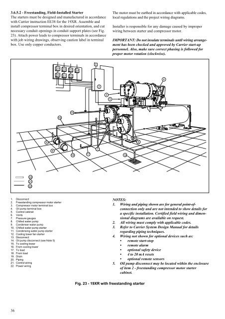
3.6.5.2 - Freestanding, Field-Installed Starter<br />
The starters must be designed and manufactured in accordance<br />
with <strong>Carrier</strong> instruction EE38 for the <strong>19XR</strong>. Assemble and<br />
install compressor terminal box in desired orientation, and cut<br />
necessary conduit openings in conduit support plates (see Fig.<br />
23). Attach power leads to compressor terminals in accordance<br />
with job wiring drawings, observing caution label in terminal<br />
box. Use only copper conductors.<br />
36<br />
20<br />
21<br />
22<br />
16<br />
1. Disconnect<br />
2. Freestanding compressor motor starter<br />
3. Compressor motor terminal box<br />
4. Oil pump terminal box<br />
5. Control cabinet<br />
6. Vents<br />
7. Pressure gauges<br />
8. Chilled water pump<br />
9. Condenser water pump<br />
10. Chilled water pump starter<br />
11. Condensing water pump starter<br />
12. Cooling tower fan starter<br />
13. Disconnect<br />
14. Oil pump disconnect (see Note 5)<br />
15. To cooling tower<br />
16. From cooling tower<br />
17. To load<br />
18. From load<br />
19. Drain<br />
20. Piping<br />
21. Control wiring<br />
22. Power wiring<br />
15<br />
18<br />
17<br />
Fig. 23 - <strong>19XR</strong> with freestanding starter<br />
The motor must be earthed in accordance with applicable codes,<br />
local regulations and the project wiring diagrams.<br />
Installer is responsible for any damage caused by improper<br />
wiring between starter and compressor motor.<br />
IMPORTANT: Do not insulate terminals until wiring arrangement<br />
has been checked and approved by <strong>Carrier</strong> start-up<br />
personnel. Also, make sure correct phasing is followed for<br />
proper motor rotation (clockwise).<br />
19<br />
NOTES:<br />
1. Wiring and piping shown are for general point-ofconnection<br />
only and are not intended to show details for<br />
a specific installation. Certified field wiring and dimensional<br />
diagrams are available on request.<br />
2. All wiring must comply with applicable codes.<br />
3. Refer to <strong>Carrier</strong> System Design Manual for details<br />
regarding piping techniques.<br />
4. Wiring not shown for optional devices such as:<br />
remote start-stop<br />
remote alarm<br />
optional safety device<br />
4 to 20 mA resets<br />
optional remote sensors<br />
5. Oil pump disconnect may be located within the enclosure<br />
of item 2 - freestanding compressor motor starter<br />
cabinet.