19XR (PIC II) Hermetic Centrifugal Liquid Chillers 50 Hz - Carrier
19XR (PIC II) Hermetic Centrifugal Liquid Chillers 50 Hz - Carrier
19XR (PIC II) Hermetic Centrifugal Liquid Chillers 50 Hz - Carrier

Create successful ePaper yourself
Turn your PDF publications into a flip-book with our unique Google optimized e-Paper software.
3.4 - Install machine supports<br />
Typical applications of these units are in refrigeration<br />
systems, and they do not require earthquake resistance.<br />
Earthquake resistance has not been verified.<br />
3.4.1 - Install standard isolation<br />
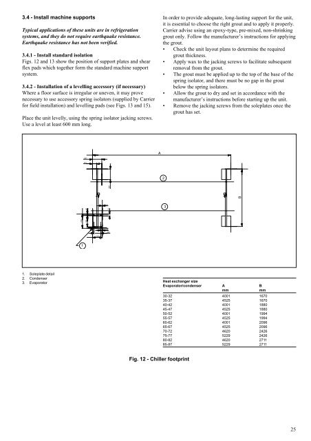
Figs. 12 and 13 show the position of support plates and shear<br />
flex pads which together form the standard machine support<br />
system.<br />
3.4.2 - Installation of a levelling accessory (if necessary)<br />
Where a floor surface is irregular or uneven, it may prove<br />
necessary to use accessory spring isolators (supplied by <strong>Carrier</strong><br />
for field installation) and levelling pads (see Figs. 13 and 15).<br />
Place the unit levelly, using the spring isolator jacking screws.<br />
Use a level at least 600 mm long.<br />
1<br />
In order to provide adequate, long-lasting support for the unit,<br />
it is essential to choose the right grout and to apply it properly.<br />
<strong>Carrier</strong> advise using an epoxy-type, pre-mixed, non-shrinking<br />
grout only. Follow the manufacturer’s instructions for applying<br />
the grout.<br />
Check the unit layout plans to determine the required<br />
grout thickness.<br />
Apply wax to the jacking screws to facilitate subsequent<br />
removal from the grout.<br />
The grout must be applied up to the top of the base of the<br />
spring isolator, and there must be no gap in the grout<br />
below the spring isolators.<br />
Allow the grout to dry and set in accordance with the<br />
manufacturer’s instructions before starting up the unit.<br />
Remove the jacking screws from the soleplates once the<br />
grout has set.<br />
1. Soleplate detail<br />
2.<br />
3.<br />
Condenser<br />
Evaporator Heat exchanger size<br />
Evaporator/condenser A B<br />
mm mm<br />
30-32 4001 1670<br />
35-37 4525 1670<br />
40-42 4001 1880<br />
45-47 4525 1880<br />
<strong>50</strong>-52 4001 1994<br />
55-57 4525 1994<br />
60-62 4001 2096<br />
65-67 4525 2096<br />
70-72 4620 2426<br />
75-77 5229 2426<br />
80-82 4620 2711<br />
85-87 5229 2711<br />
Fig. 12 - Chiller footprint<br />
2<br />
3<br />
25