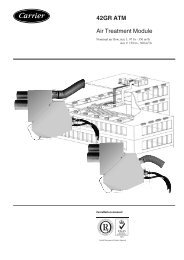
19XR (PIC II) Hermetic Centrifugal Liquid Chillers 50 Hz - Carrier
19XR (PIC II) Hermetic Centrifugal Liquid Chillers 50 Hz - Carrier
19XR (PIC II) Hermetic Centrifugal Liquid Chillers 50 Hz - Carrier

Create successful ePaper yourself
Turn your PDF publications into a flip-book with our unique Google optimized e-Paper software.
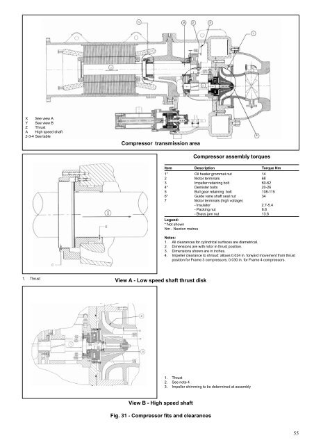
X See view A<br />
Y See view B<br />
Z Thrust<br />
A High speed shaft<br />
2-3-4 See table<br />
1. Thrust<br />
Compressor transmission area<br />
View A - Low speed shaft thrust disk<br />
View B - High speed shaft<br />
Compressor assembly torques<br />
Item Description Torque Nm<br />
1* Oil heater grommet nut 14<br />
2 Motor terminals 68<br />
3 Impeller retaining bolt 60-62<br />
4* Demister bolts 20-26<br />
5 Bull gear retaining bolt 108-115<br />
6* Guide vane shaft seal nut 34<br />
7 Motor terminals (high voltage)<br />
- Insulator 2.7-5.4<br />
- Packing nut 6.8<br />
Legend:<br />
* Not shown<br />
- Brass jam nut 13.6<br />
Nm - Newton metres<br />
Notes:<br />
1. All clearances for cylindrical surfaces are diametrical.<br />
2. Dimensions are with rotor in thrust position.<br />
3. Dimensions shown are in inches.<br />
4. Impeller clearance to shroud: allows 0.024 in. forward movement from thrust<br />
position for Frame 3 compressors; 0.030 in. for Frame 4 compressors.<br />
1. Thrust<br />
2. See note 4<br />
3. Impeller shimming to be determined at assembly<br />
Fig. 31 - Compressor fits and clearances<br />
55