19XR (PIC II) Hermetic Centrifugal Liquid Chillers 50 Hz - Carrier
19XR (PIC II) Hermetic Centrifugal Liquid Chillers 50 Hz - Carrier
19XR (PIC II) Hermetic Centrifugal Liquid Chillers 50 Hz - Carrier

Create successful ePaper yourself
Turn your PDF publications into a flip-book with our unique Google optimized e-Paper software.
3.6.4 - Make the necessary connections for the outgoing<br />
control signals<br />
Connect the auxiliary equipment, the chilled water pumps and<br />
the condenser water pumps, as well as the additional alarms, as<br />
indicated in the job wiring diagrams.<br />
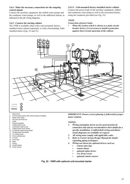
3.6.5 - Connect the starting cabinet<br />
The <strong>19XR</strong> is available either with a unit-mounted, factoryinstalled<br />
starter cabinet (optional), or with a freestanding, fieldinstalled<br />
starter (Figs. 22 and 23).<br />
17<br />
18<br />
19<br />
1. Disconnect<br />
2. Unit mounted starter with control (factory-installed)<br />
3. Guide vane motor<br />
4. Oil pump terminal box<br />
5. Vents<br />
6. Pressure gauges<br />
7. Chilled water pump<br />
8. Condenser water pump<br />
9. Chilled water pump starter<br />
10. Condenser water pump starter<br />
11. Cooling tower fan starter<br />
12. To cooling tower<br />
13. From cooling tower<br />
14. To load<br />
15. From load<br />
16. Drain<br />
17. Piping<br />
18. Control wiring<br />
19. Power wiring<br />
8<br />
7<br />
13<br />
18<br />
12<br />
15<br />
14<br />
Fig. 22 - <strong>19XR</strong> with optional unit-mounted starter<br />
3.6.5.1 - Unit-mounted factory-installed starter cabinet<br />
Connect the power leads of the auxiliary equipment, chilled<br />
and condenser water pump as well as the associated alarms,<br />
using the conductor provided (see Fig. 22).<br />
NOTE:<br />
Connection of power leads:<br />
When the section switch is chosen as a main circuitbreaker<br />
device, it is necessary to install a protection<br />
against short circuits upstream of the cabinet.<br />
16<br />
IMPORTANT: Ensure correct phasing is followed for proper<br />
motor rotation.<br />
NOTES:<br />
1. Wiring and piping shown are for general point-ofconnection<br />
only and are not intended to show details for a<br />
specific installation. Certified field wiring and dimensional<br />
diagrams are available on request.<br />
2. All wiring must comply with applicable codes.<br />
3. Refer to <strong>Carrier</strong> System Design Manual for details<br />
regarding piping techniques.<br />
4. Wiring not shown for optional devices such as:<br />
remote start-stop<br />
remote alarm<br />
optional safety device<br />
4 to 20 mA resets<br />
optional remote sensors<br />
3<br />
35