19XR (PIC II) Hermetic Centrifugal Liquid Chillers 50 Hz - Carrier
19XR (PIC II) Hermetic Centrifugal Liquid Chillers 50 Hz - Carrier
19XR (PIC II) Hermetic Centrifugal Liquid Chillers 50 Hz - Carrier

You also want an ePaper? Increase the reach of your titles
YUMPU automatically turns print PDFs into web optimized ePapers that Google loves.
6. Valve off the vacuum pump, stop the pump, and record<br />
the instrument reading.<br />
7. After a 2-hour wait, take another instrument reading. If<br />
the reading has not changed, dehydration is complete. If<br />
the reading indicates vacuum loss, repeat Steps 4 and 5.<br />
8. If the reading continues to change after several attempts,<br />
perform a leak test up to the maximum 1103 kPa pressure.<br />
Locate and repair the leak, and repeat dehydration.<br />
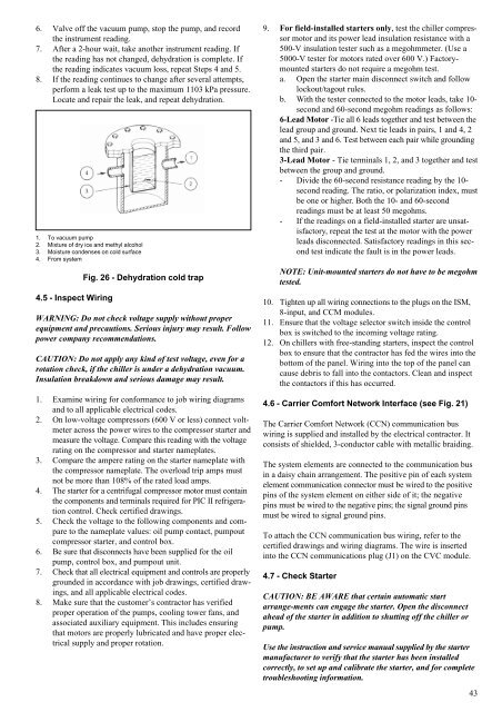
1. To vacuum pump<br />
2. Mixture of dry ice and methyl alcohol<br />
3. Moisture condenses on cold surface<br />
4. From system<br />
4.5 - Inspect Wiring<br />
Fig. 26 - Dehydration cold trap<br />
WARNING: Do not check voltage supply without proper<br />
equipment and precautions. Serious injury may result. Follow<br />
power company recommendations.<br />
CAUTION: Do not apply any kind of test voltage, even for a<br />
rotation check, if the chiller is under a dehydration vacuum.<br />
Insulation breakdown and serious damage may result.<br />
1. Examine wiring for conformance to job wiring diagrams<br />
and to all applicable electrical codes.<br />
2. On low-voltage compressors (600 V or less) connect voltmeter<br />
across the power wires to the compressor starter and<br />
measure the voltage. Compare this reading with the voltage<br />
rating on the compressor and starter nameplates.<br />
3. Compare the ampere rating on the starter nameplate with<br />
the compressor nameplate. The overload trip amps must<br />
not be more than 108% of the rated load amps.<br />
4. The starter for a centrifugal compressor motor must contain<br />
the components and terminals required for <strong>PIC</strong> <strong>II</strong> refrigeration<br />
control. Check certified drawings.<br />
5. Check the voltage to the following components and compare<br />
to the nameplate values: oil pump contact, pumpout<br />
compressor starter, and control box.<br />
6. Be sure that disconnects have been supplied for the oil<br />
pump, control box, and pumpout unit.<br />
7. Check that all electrical equipment and controls are properly<br />
grounded in accordance with job drawings, certified drawings,<br />
and all applicable electrical codes.<br />
8. Make sure that the customer’s contractor has verified<br />
proper operation of the pumps, cooling tower fans, and<br />
associated auxiliary equipment. This includes ensuring<br />
that motors are properly lubricated and have proper electrical<br />
supply and proper rotation.<br />
9. For field-installed starters only, test the chiller compressor<br />
motor and its power lead insulation resistance with a<br />
<strong>50</strong>0-V insulation tester such as a megohmmeter. (Use a<br />
<strong>50</strong>00-V tester for motors rated over 600 V.) Factorymounted<br />
starters do not require a megohm test.<br />
a. Open the starter main disconnect switch and follow<br />
lockout/tagout rules.<br />
b. With the tester connected to the motor leads, take 10second<br />
and 60-second megohm readings as follows:<br />
6-Lead Motor -Tie all 6 leads together and test between the<br />
lead group and ground. Next tie leads in pairs, 1 and 4, 2<br />
and 5, and 3 and 6. Test between each pair while grounding<br />
the third pair.<br />
3-Lead Motor - Tie terminals 1, 2, and 3 together and test<br />
between the group and ground.<br />
- Divide the 60-second resistance reading by the 10second<br />
reading. The ratio, or polarization index, must<br />
be one or higher. Both the 10- and 60-second<br />
readings must be at least <strong>50</strong> megohms.<br />
- If the readings on a field-installed starter are unsatisfactory,<br />
repeat the test at the motor with the power<br />
leads disconnected. Satisfactory readings in this second<br />
test indicate the fault is in the power leads.<br />
NOTE: Unit-mounted starters do not have to be megohm<br />
tested.<br />
10. Tighten up all wiring connections to the plugs on the ISM,<br />
8-input, and CCM modules.<br />
11. Ensure that the voltage selector switch inside the control<br />
box is switched to the incoming voltage rating.<br />
12. On chillers with free-standing starters, inspect the control<br />
box to ensure that the contractor has fed the wires into the<br />
bottom of the panel. Wiring into the top of the panel can<br />
cause debris to fall into the contactors. Clean and inspect<br />
the contactors if this has occurred.<br />
4.6 - <strong>Carrier</strong> Comfort Network Interface (see Fig. 21)<br />
The <strong>Carrier</strong> Comfort Network (CCN) communication bus<br />
wiring is supplied and installed by the electrical contractor. It<br />
consists of shielded, 3-conductor cable with metallic braiding.<br />
The system elements are connected to the communication bus<br />
in a daisy chain arrangement. The positive pin of each system<br />
element communication connector must be wired to the positive<br />
pins of the system element on either side of it; the negative<br />
pins must be wired to the negative pins; the signal ground pins<br />
must be wired to signal ground pins.<br />
To attach the CCN communication bus wiring, refer to the<br />
certified drawings and wiring diagrams. The wire is inserted<br />
into the CCN communications plug (J1) on the CVC module.<br />
4.7 - Check Starter<br />
CAUTION: BE AWARE that certain automatic start<br />
arrange-ments can engage the starter. Open the disconnect<br />
ahead of the starter in addition to shutting off the chiller or<br />
pump.<br />
Use the instruction and service manual supplied by the starter<br />
manufacturer to verify that the starter has been installed<br />
correctly, to set up and calibrate the starter, and for complete<br />
troubleshooting information.<br />
43