19XR (PIC II) Hermetic Centrifugal Liquid Chillers 50 Hz - Carrier
19XR (PIC II) Hermetic Centrifugal Liquid Chillers 50 Hz - Carrier
19XR (PIC II) Hermetic Centrifugal Liquid Chillers 50 Hz - Carrier

You also want an ePaper? Increase the reach of your titles
YUMPU automatically turns print PDFs into web optimized ePapers that Google loves.
To pressurize with dry nitrogen<br />
Another method of leak testing is to pressurize with nitrogen<br />
only and to use a soap bubble solution or an ultrasonic leak<br />
detector to determine if leaks are present. This should only be<br />
done if all refrigerant has been evacuated from the vessel.<br />
1. Connect a copper tube from the pressure regulator on the<br />
cylinder to the refrigerant charging valve.<br />
2. Never apply full cylinder pressure to the pressurizing line.<br />
Follow the listed sequence.<br />
3. Open the charging valve fully.<br />
4. Slowly open the cylinder regulating valve.<br />
5. Observe the pressure gauge on the chiller and close the<br />
regulating valve when the pressure reaches test level. Do<br />
not exceed 965 kPa.<br />
6. Close the charging valve on the chiller. Remove the<br />
copper tube if no longer required.<br />
Repair the leak, retest and apply standing vacuum test<br />
After pressurizing the chiller, test for leaks with an electronic<br />
leak detector, soap bubble solution, or an ultrasonic leak<br />
detector. Bring the chiller back to atmospheric pressure, repair<br />
any leaks found, and retest.<br />
After retesting and finding no leaks, apply a standing vacuum<br />
test, and then dehydrate the chiller. Refer to the Standing<br />
Vacuum Test and Chiller Dehydration in the Before Initial<br />
Start-Up section.<br />
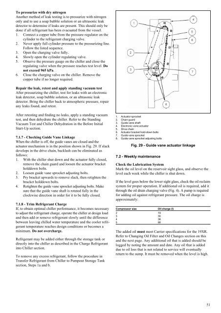
7.1.7 - Checking Guide Vane Linkage<br />
When the chiller is off, the guide vanes are closed and the<br />
actuator mechanism is in the position shown in Fig. 29. If slack<br />
develops in the drive chain, backlash can be eliminated as<br />
follows:<br />
1. With the chiller shut down and the actuator fully closed,<br />
remove the chain guard and loosen the actuator bracket<br />
holddown bolts.<br />
2. Loosen guide vane sprocket adjusting bolts.<br />
3. Pry bracket upwards to remove slack, then retighten the<br />
bracket holddown bolts.<br />
4. Retighten the guide vane sprocket adjusting bolts. Make<br />
sure that the guide vane shaft is rotated fully in the<br />
clockwise direction in order for it to be fully closed.<br />
7.1.8 - Trim Refrigerant Charge<br />
If, to obtain optimal chiller performance, it becomes necessary<br />
to adjust the refrigerant charge, operate the chiller at design load<br />
and then add or remove refrigerant slowly until the difference<br />
between leaving chilled water temperature and the cooler refrigerant<br />
temperature reaches design conditions or becomes a<br />
minimum. Do not overcharge.<br />
Refrigerant may be added either through the storage tank or<br />
directly into the chiller as described in the Charge Refrigerant<br />
into Chiller section.<br />
To remove any excess refrigerant, follow the procedure in<br />
Transfer Refrigerant from Chiller to Pumpout Storage Tank<br />
section, Steps 1a and b.<br />
1. Actuator sprocket<br />
2. Chain guard<br />
3. Guide vane shaft<br />
4. Electronic vane actuator<br />
5. Drive chain<br />
6. Actuator bracket hold-down bolts<br />
7. Guide vane sprocket<br />
8. Guide vane sprocket adjusting bolts<br />
Fig. 29 - Guide vane actuator linkage<br />
7.2 - Weekly maintenance<br />
Check the Lubrication System<br />
Mark the oil level on the reservoir sight glass, and observe the<br />
level each week while the chiller is shut down.<br />
If the level goes below the lower sight glass, check the oil reclaim<br />
system for proper operation. If additional oil is required, add it<br />
through the oil drain charging valve (Fig. 4). A pump is required<br />
for adding oil against refrigerant pressure. The oil charge is<br />
approximately:<br />
Compressor size Oil charge (l)<br />
2 19<br />
3 30<br />
4 38<br />
5 68<br />
The added oil must meet <strong>Carrier</strong> specifications for the <strong>19XR</strong>.<br />
Refer to Changing Oil Filter and Oil Changes section on this<br />
and the next page. Any additional oil that is added should be<br />
logged by noting the amount and date. Any oil that is added<br />
due to oil loss that is not related to service will eventually<br />
return to the sump. It must be removed when the level is high.<br />
51