19XR (PIC II) Hermetic Centrifugal Liquid Chillers 50 Hz - Carrier
19XR (PIC II) Hermetic Centrifugal Liquid Chillers 50 Hz - Carrier
19XR (PIC II) Hermetic Centrifugal Liquid Chillers 50 Hz - Carrier

You also want an ePaper? Increase the reach of your titles
YUMPU automatically turns print PDFs into web optimized ePapers that Google loves.
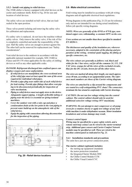
3.5.2 - Install vent piping to relief devices<br />
The <strong>19XR</strong> chiller is factory equipped with relief devices on the<br />
cooler and condenser shells. Refer to Fig. 20 for size and<br />
location of relief devices.<br />
The safety valves are installed on ball valves, that are leadsealed<br />
in the open position.<br />
These valves permit isolating and removing the safety valve<br />
for calibration and replacement.<br />
If a safety valve is replaced, do not leave the machine without<br />
safety valves. Only remove the safety valve, if the risk of fire<br />
is completely controlled and under the responsibility of the<br />
user. Half the safety valves are enough to protect against fire.<br />
The other half can be removed for replacement (see "Safety<br />
considerations".<br />
Vent relief devices to the outdoors in accordance with the<br />
applicable national standard (for example, NFE 35400 in<br />
France and EN 378 when applicable) for the safety of chilling<br />
devices as well as any other applicable codes.<br />
DANGER: Refrigerant discharged into confined spaces can<br />
displace oxygen and cause asphyxiation.<br />
1. If relief devices are manifolded, the cross-sectional area<br />
of the relief pipe must at least equal the sum of the areas<br />
required for individual relief pipes.<br />
2. Provide a pipe plug near outlet side of each relief device<br />
for leak testing. Provide pipe fittings that allow vent piping<br />
to be disconnected periodically for inspection of<br />
valve mechanism.<br />
3. Piping to relief devices must not apply stress to the device.<br />
Adequately support piping. A length of flexible tubing or<br />
piping near the device is essential on spring-isolated<br />
machines.<br />
4. Cover the outdoor vent with a rain cap and place a<br />
condensation drain at the low point in the vent piping to<br />
prevent water build-up on the atmospheric side of the<br />
relief device.<br />
5. Equip the piping with connections allowing disconnection<br />
for the inspection of the piping.<br />
30<br />
Fig. 20 - Relief device locations<br />
3.6 - Make electrical connections<br />
Field wiring must be installed in accordance with job wiring<br />
diagrams and all applicable electrical local regulations.<br />
Wiring diagrams in this publication (Fig. 21-23) are for reference<br />
only and are not intended for use during actual installation;<br />
follow job specific wiring diagrams.<br />
NOTE: Wires are generally of the 05VK or 07VK type, nontinned<br />
copper core, withstanding a constant 105ºC on the core.<br />
Cross sections are not smaller than those specified in standard<br />
EN 60204-1.<br />
The thicknesses and quality of the insulation are, wherever<br />
necessary, adapted to the constraints of the placing and preparation<br />
of the wiring, terminal spade tagging, the fitting of<br />
specific connectors, etc.<br />
The wire colours are generally as follows: red, black and<br />
white for the 3 bus wires, red for all the common 24, 115, 230<br />
VAC wires, orange for all the wires of the excluded circuits,<br />
blue for the DC circuits, brown for all the other wires.<br />
The wires are marked all along their length, one mark approx.<br />
every 40 mm, according to an equipotential system. The reference<br />
mark numbers are those of the <strong>Carrier</strong> wiring diagram.<br />
The wires are attached by a clip around the components and<br />
are routed in a self-extinguishing PVC chute! The connectors<br />
terminate the bus strand in conformity with <strong>Carrier</strong> drawings.<br />
CAUTION: Do not run low voltage wiring into the control<br />
cabinet. The control cabinet should only be used for<br />
additional extra-low voltage wiring (<strong>50</strong> V maximum).<br />
WARNING: Do not attempt to start compressor or oil pump<br />
(even for a rotation check) or apply test voltage of any kind<br />
while machine is under dehydration vacuum. Motor insulation<br />
breakdown and serious damage may result.<br />
Connect control inputs<br />
Wiring may be specified for a spare safety switch, and a<br />
remote start/stop contact can be wired to the starter terminal<br />
strip. Additional spare sensors and <strong>Carrier</strong> Comfort Network<br />
modules may be specified as well. These are wired to the<br />
machine control panel as indicated in Fig. 21.<br />
3.6.1 Installation standards and precautions<br />
The units have just one power connection point.<br />
The starter cabinet (optional) includes:<br />
the starting-up equipment (standard)<br />
the motor protection (standard)<br />
the Integrated Starter Module ISM<br />
the Chiller Control Module CCM<br />
the Chiller Visual Control CVC