19XR (PIC II) Hermetic Centrifugal Liquid Chillers 50 Hz - Carrier
19XR (PIC II) Hermetic Centrifugal Liquid Chillers 50 Hz - Carrier
19XR (PIC II) Hermetic Centrifugal Liquid Chillers 50 Hz - Carrier

You also want an ePaper? Increase the reach of your titles
YUMPU automatically turns print PDFs into web optimized ePapers that Google loves.
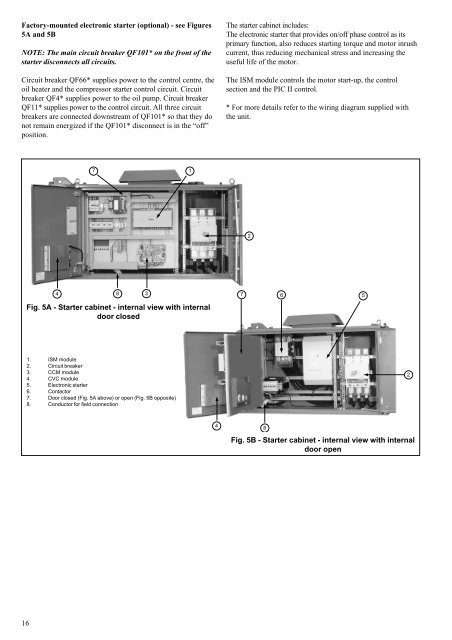
Factory-mounted electronic starter (optional) - see Figures<br />
5A and 5B<br />
NOTE: The main circuit breaker QF101* on the front of the<br />
starter disconnects all circuits.<br />
Circuit breaker QF66* supplies power to the control centre, the<br />
oil heater and the compressor starter control circuit. Circuit<br />
breaker QF4* supplies power to the oil pump. Circuit breaker<br />
QF11* supplies power to the control circuit. All three circuit<br />
breakers are connected downstream of QF101* so that they do<br />
not remain energized if the QF101* disconnect is in the “off”<br />
position.<br />
16<br />
4<br />
7<br />
1<br />
8 3<br />
7<br />
6<br />
5<br />
Fig. 5A - Starter cabinet - internal view with internal<br />
door closed<br />
1. ISM module<br />
2. Circuit breaker<br />
3. CCM module<br />
4. CVC module<br />
5. Electronic starter<br />
6. Contactor<br />
7. Door closed (Fig. 5A above) or open (Fig. 5B opposite)<br />
8. Conductor for field connection<br />
4<br />
The starter cabinet includes:<br />
The electronic starter that provides on/off phase control as its<br />
primary function, also reduces starting torque and motor inrush<br />
current, thus reducing mechanical stress and increasing the<br />
useful life of the motor.<br />
The ISM module controls the motor start-up, the control<br />
section and the <strong>PIC</strong> <strong>II</strong> control.<br />
* For more details refer to the wiring diagram supplied with<br />
the unit.<br />
2<br />
8<br />
Fig. 5B - Starter cabinet - internal view with internal<br />
door open<br />
2