19XR (PIC II) Hermetic Centrifugal Liquid Chillers 50 Hz - Carrier
19XR (PIC II) Hermetic Centrifugal Liquid Chillers 50 Hz - Carrier
19XR (PIC II) Hermetic Centrifugal Liquid Chillers 50 Hz - Carrier
Create successful ePaper yourself
Turn your PDF publications into a flip-book with our unique Google optimized e-Paper software.
4<br />
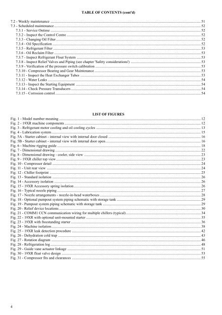
TABLE OF CONTENTS (cont'd)<br />
7.2 - Weekly maintenance ................................................................................................................................................................. 51<br />
7.3 - Scheduled maintenance ............................................................................................................................................................. 52<br />
7.3.1 - Service Ontime ................................................................................................................................................................. 52<br />
7.3.2 - Inspect the Control Centre ................................................................................................................................................ 52<br />
7.3.3 - Changing Oil Filter ........................................................................................................................................................... 52<br />
7.3.4 - Oil Specification ............................................................................................................................................................... 52<br />
7.3.5 - Refrigerant Filter .............................................................................................................................................................. 53<br />
7.3.6 - Oil Reclaim Filter ............................................................................................................................................................. 53<br />
7.3.7 - Inspect Refrigerant Float System ..................................................................................................................................... 53<br />
7.3.8 - Inspect Relief Valves and Piping (see chapter 'Safety considerations') ........................................................................... 53<br />
7.3.9 - Verification of the pressure switch calibration ................................................................................................................. 53<br />
7.3.10 - Compressor Bearing and Gear Maintenance.................................................................................................................. 53<br />
7.3.11 - Inspect the Heat Exchanger Tubes ................................................................................................................................. 53<br />
7.3.12 - Water Leaks .................................................................................................................................................................... 54<br />
7.3.13 - Inspect the Starting Equipment ...................................................................................................................................... 54<br />
7.3.14 - Check Pressure Transducers ........................................................................................................................................... 54<br />
7.3.15 - Corrosion control ............................................................................................................................................................ 54<br />
LIST OF FIGURES<br />
Fig. 1 - Model number meaning ........................................................................................................................................................ 12<br />
Fig. 2 - <strong>19XR</strong> machine components .................................................................................................................................................. 12<br />
Fig. 3 - Refrigerant motor cooling and oil cooling cycles ................................................................................................................ 13<br />
Fig. 4 - Lubrication system................................................................................................................................................................ 15<br />
Fig. 5A - Starter cabinet - internal view with internal door closed ................................................................................................... 16<br />
Fig. 5B - Starter cabinet - internal view with internal door open...................................................................................................... 16<br />
Fig. 6 - Machine rigging guide .......................................................................................................................................................... 18<br />
Fig. 7 - Dimensional drawing ............................................................................................................................................................ 22<br />
Fig. 8 - Dimensional drawing - cooler, side view ............................................................................................................................. 23<br />
Fig. 9 - <strong>19XR</strong> chiller top view ........................................................................................................................................................... 23<br />
Fig. 10 - Compressor detail ............................................................................................................................................................... 24<br />
Fig. 11 - Unit rear view ..................................................................................................................................................................... 24<br />
Fig. 12 - Chiller footprint .................................................................................................................................................................. 25<br />
Fig. 13 - Standard isolation ............................................................................................................................................................... 26<br />
Fig. 14 - Accessory isolation ............................................................................................................................................................. 26<br />
Fig. 15 - <strong>19XR</strong> Accessory spring isolation........................................................................................................................................ 26<br />
Fig. 16 - Typical nozzle piping .......................................................................................................................................................... 27<br />
Fig. 17 - Nozzle arrangements - nozzle-in-head waterboxes ............................................................................................................ 28<br />
Fig. 18 - Optional pumpout system piping schematic with storage tank .......................................................................................... 29<br />
Fig. 19 - Pumpout system piping schematic with storage tank ......................................................................................................... 29<br />
Fig. 20 - Relief device locations ........................................................................................................................................................ 30<br />
Fig. 21 - COMM1 CCN communication wiring for multiple chillers (typical) ................................................................................ 34<br />
Fig. 22 - <strong>19XR</strong> with optional unit-mounted starter ........................................................................................................................... 35<br />
Fig. 23 - <strong>19XR</strong> with freestanding starter ........................................................................................................................................... 36<br />
Fig. 24 - Machine isolation................................................................................................................................................................ 38<br />
Fig. 25 - <strong>19XR</strong> leak detection procedure .......................................................................................................................................... 42<br />
Fig. 26 - Dehydration cold trap ......................................................................................................................................................... 43<br />
Fig. 27 - Rotation diagram ................................................................................................................................................................ 46<br />
Fig. 28 - Refrigeration log ................................................................................................................................................................. 48<br />
Fig. 29 - Guide vane actuator linkage ............................................................................................................................................... 51<br />
Fig. 30 - <strong>19XR</strong> float valve design ..................................................................................................................................................... 53<br />
Fig. 31 - Compressor fits and clearances .......................................................................................................................................... 55


