19XR (PIC II) Hermetic Centrifugal Liquid Chillers 50 Hz - Carrier
19XR (PIC II) Hermetic Centrifugal Liquid Chillers 50 Hz - Carrier
19XR (PIC II) Hermetic Centrifugal Liquid Chillers 50 Hz - Carrier

You also want an ePaper? Increase the reach of your titles
YUMPU automatically turns print PDFs into web optimized ePapers that Google loves.
3. Cut a CCN wire and strip the ends of the RED, WHITE,<br />
and BLACK conductors (Molex type strippable<br />
connectors - supplier ref. No. 08-<strong>50</strong>-0189).<br />
4. Using a wirenut, connect the drain wires together.<br />
5. Insert and secure the RED wire to Terminal 1 of the J1<br />
connector.<br />
6. Insert and secure the WHITE wire to Terminal 2 of the J1<br />
connector.<br />
7. Insert and secure the BLACK wire to Terminal 3 of the J1<br />
connector.<br />
8. Mount a terminal strip in a convenient location.<br />
9. Connect the opposite ends of each conductor to separate<br />
terminals on the terminal strip.<br />
10. Cut another CCN wire and strip the ends of the<br />
conductors.<br />
11. Connect the RED wire to the matching location on the<br />
terminal strip.<br />
12. Connect the WHITE wire to the matching location on the<br />
terminal strip.<br />
13. Connect the BLACK wire to the matching location on the<br />
terminal strip.<br />
38<br />
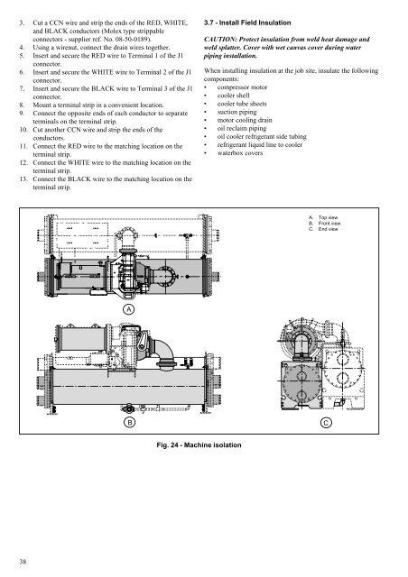
A<br />
B C<br />
Fig. 24 - Machine isolation<br />
3.7 - Install Field Insulation<br />
CAUTION: Protect insulation from weld heat damage and<br />
weld splatter. Cover with wet canvas cover during water<br />
piping installation.<br />
When installing insulation at the job site, insulate the following<br />
components:<br />
compressor motor<br />
cooler shell<br />
cooler tube sheets<br />
suction piping<br />
motor cooling drain<br />
oil reclaim piping<br />
oil cooler refrigerant side tubing<br />
refrigerant liquid line to cooler<br />
waterbox covers<br />
A. Top view<br />
B. Front view<br />
C. End view