19XR (PIC II) Hermetic Centrifugal Liquid Chillers 50 Hz - Carrier
19XR (PIC II) Hermetic Centrifugal Liquid Chillers 50 Hz - Carrier
19XR (PIC II) Hermetic Centrifugal Liquid Chillers 50 Hz - Carrier

Create successful ePaper yourself
Turn your PDF publications into a flip-book with our unique Google optimized e-Paper software.
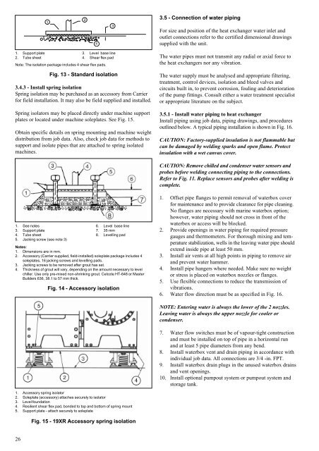
1. Support plate<br />
2. Tube sheet<br />
Note: The isolation package includes 4 shear flex pads.<br />
26<br />
Fig. 13 - Standard isolation<br />
3.4.3 - Install spring isolation<br />
Spring isolation may be purchased as an accessory from <strong>Carrier</strong><br />
for field installation. It may also be field supplied and installed.<br />
Spring isolators may be placed directly under machine support<br />
plates or located under machine soleplates. See Fig. 15.<br />
Obtain specific details on spring mounting and machine weight<br />
distribution from job data. Also, check job data for methods to<br />
support and isolate pipes that are attached to spring isolated<br />
machines.<br />
1. See notes<br />
3. Support plate<br />
4. Tube sheet<br />
5. Jacking screw (see note 3)<br />
3. Level base line<br />
4. Shear flex pad<br />
6. Level base line<br />
7. 35 mm<br />
8. Levelling pad<br />
Notes:<br />
1. Dimensions are in mm.<br />
2. Accessory (<strong>Carrier</strong> supplied, field-installed) soleplate package includes 4<br />
soleplates, 16 jacking screws and levelling pads.<br />
3. Jacking screws to be removed after grout has set.<br />
4. Thickness of grout will vary, depending on the amount necessary to level<br />
chiller. Use only pre-mixed non-shrinking grout. Celcote HT-648 or Master<br />
Builders 636, 38.1 to 57 mm thick.<br />
Fig. 14 - Accessory isolation<br />
1. Accessory spring isolator<br />
2. Soleplate (accessory) attaches securely to isolator<br />
3. Level foundation<br />
4. Resilient shear flex pad, bonded to top and bottom of spring mount<br />
5. Support plate - attach securely to soleplate<br />
Fig. 15 - <strong>19XR</strong> Accessory spring isolation<br />
3.5 - Connection of water piping<br />
For size and position of the heat exchanger water inlet and<br />
outlet connections refer to the certified dimensional drawings<br />
supplied with the unit.<br />
The water pipes must not transmit any radial or axial force to<br />
the heat exchangers nor any vibration.<br />
The water supply must be analysed and appropriate filtering,<br />
treatment, control devices, isolation and bleed valves and<br />
circuits built in, to prevent corrosion, fouling and deterioration<br />
of the pump fittings. Consult either a water treatment specialist<br />
or appropriate literature on the subject.<br />
3.5.1 - Install water piping to heat exchanger<br />
Install piping using job data, piping drawings, and procedures<br />
outlined below. A typical piping installation is shown in Fig. 16.<br />
CAUTION: Factory-supplied insulation is not flammable but<br />
can be damaged by welding sparks and open flame. Protect<br />
insulation with a wet canvas cover.<br />
CAUTION: Remove chilled and condenser water sensors and<br />
probes before welding connecting piping to the connections.<br />
Refer to Fig. 11. Replace sensors and probes after welding is<br />
complete.<br />
1. Offset pipe flanges to permit removal of waterbox cover<br />
for maintenance and to provide clearance for pipe cleaning.<br />
No flanges are necessary with marine waterbox option;<br />
however, water piping should not cross in front of the<br />
waterbox or access will be blocked.<br />
2. Provide openings in water piping for required pressure<br />
gauges and thermometers. For thorough mixing and temperature<br />
stabilization, wells in the leaving water pipe should<br />
extend inside pipe at least <strong>50</strong> mm.<br />
3. Install air vents at all high points in piping to remove air<br />
and prevent water hammer.<br />
4. Install pipe hangers where needed. Make sure no weight<br />
or stress is placed on waterbox nozzles or flanges.<br />
5. Use flexible connections to reduce the transmission of<br />
vibrations.<br />
6. Water flow direction must be as specified in Fig. 16.<br />
NOTE: Entering water is always the lower of the 2 nozzles.<br />
Leaving water is always the upper nozzle for cooler or<br />
condenser.<br />
7. Water flow switches must be of vapour-tight construction<br />
and must be installed on top of pipe in a horizontal run<br />
and at least 5 pipe diameters from any bend.<br />
8. Install waterbox vent and drain piping in accordance with<br />
individual job data. All connections are 3/4 -in. FPT.<br />
9. Install waterbox drain plugs in the unused waterbox drains<br />
and vent openings.<br />
10. Install optional pumpout system or pumpout system and<br />
storage tank.